Out of the pxi-4461 using SignalExpress
I am trying to generate output using SignalExpress 2010 signals and a new card PXI-4461. To do this I am creating an analog sine wave at the stage of 'Create an analog Signal' and the output which, off AO0, using step "DAQmx generate". Then I use 'DAQmx acquire' to see what is actually output the signal being produced is not a sine wave, but some other distorted signal. I tested on the channels of entry with a function generator, and they seem to register all these signals well, so I wonder if there is something wrong with the channels of output in this map, or if I use the steps wrong for the output signal. Any contribution is appreciated.
I got a telephone support on this and it is now resolved.
Tags: NI Hardware
Similar Questions
-
Acquire more than 2047 samples with the PXI-4461 instaled in SMU-1073
Hi all, I would ask you for help with the buffer limit.
I intend to buy digitizer PXI-4461 and he instal in SMU-1073 chassis, namely control via MXI Express of Labview installed on a separate computer.
What I need:
-to acquire data of a single channel of AI, but at least a sequence of 20 kS by a acquire task, in some situations until 200kS by a task to acquire.
The question:
- I can gain more than 2047 samples in a single sequence, like 200kS, with the PXI-4461 installed in SMU-1073?
Internal buffer of the PXI-4461 is reserved to 2047 samples. So I'm not sure if Labview can download remotely via MXI Express the data in the buffer of the PXI-4461 via MXI Express fast enough without any affection of the sampling program.
-in the case, this PXI-4461 with SMU-1073 isn't the right combination, what chassis and a controller can do?
Thanks much for the reply
Jan
It will work for you.
The on-board buffer 2047-sample is used only as a backup if the flow of data to the PC host (via MXI Express in this case) is not fast enough... that it will be (explained below). DAQmx transfers data from the buffer of the device to the host PC as fast as he can and, in ideal conditions, should not save the buffer 2047 much at all.
Let's just say you get 110 MB/s (randomly from a MXI data sheet) flow on your MXI connection. The 4461 has 2 analog inputs, which will be at 24 bits, we just round 32-bit in case it transfers the data in this way.
4 bytes/sample (32 bit) x 200,000 s/s x 2 (channels) = 1.6 MB/s, which is well below the 110 MB/s, which will make the MXI link.
clear as mud?
Germano-
-
The PXI-4461 connections and text based programming
Hello
I looking for a guide-schedule based on text for the PCI card, / AO PXI-4461 24 bit. Currently, I am able to program it similar to the PXI-6259 but could not find a way to set it up as (differential, Pseudo-differentiel) in order to obtain the correct output impedance.
Is there a hardware (user) for PXI-4461 guide?
I use Visual c# to encode the PXI-4461. How can I determine the location of the classes and the specific methods for the PXI-4461.
Thank you.
Anand
-
What is the maximum voltage of the members of the PXI 4461 gain 20 dB?
I use a Board, PXI-4461 sample sine wave with an amplitude of slightly greater than 1 V peak (1.0005 V). The gain of the Board of Directors is set at 20 dB and the input range should be from-1 to + 1 V V! That's why I expect that see a saturation of the converter ADC when the input signal is greater than 1 V. However, I do not respect this saturation of the output value, and I don't understand why?
Could someone explain that to me?
Thank you in advance.
Frédéric
Hello Frederic,.
almost all NI DAQ devices I know has a small "margin of safety" in each range given acquisition (usually about 0.5-2%), allowing you to accurately measure the voltage specified limit.
The exact width of this margin is not explicitly mentioned, probably to prevent users to use this line on a regular basis.
In short: there's a small safety margin, but do not count on it when designing measurement applications. ;-)
Best regards
Sebastian -
"error-200621" trying to generate 20 kHz sinusoidal aboard the AO0: 1 of the PXI-4461
Hello!
I am getting a-200621 error trying to generate a sine wave of 20 kHz the signal output of a Council of PXI-4461 0 and 1. The signal is generated for a few seconds, then the error «on-board device memory overflow negative...» "happens! Why? and how can I avoid it?
If I'm generating 1 kHz or using a single channel, all is well!
I joined the vi as well as the error message.
Here is the configuration of my system:
LabVIEW 8.5
PXI-1044 chassis with 14 locations and MXI-4 Council (optics) to communicate with the PC:
-Connector 2: OR PXI-4461
-Slot 3: OR PXI-4461
-Slot 4: OR PXI 2561
Computer:
-Intel Core 2 Quad Q9400 2.66 GHz CPU
-3.49 GB of Ram
Thank you in advance.
Frédéric
Hi Peter,.
The issue is resolved in fact to increase the number of samples that are written in the buffer!
Thanks to you and Laurent!
Frédéric
-
Application errors of the RT with the PXI-4461 with Labview real-time 9.0.1, DAQmx 9.0.2
HI -.
I recently converted a PXI time system real OS (PXI-1042 q chassis, controller PXI-8187, DAQ, PXI-4461, DAQ, PXI-6259). I can write and run DAQmx applications in real time with the 6259 very well. Whenever I try to write a labview RT app to use the 4461, however, it will fail. Note that I can use two cards through MAX I tried switching card slots, just in case it was a problem. Both cards worked with labview, the PXI chassis was before Windows.
Attached are pictures of the screw base demo I built to show the problem. Since I was a mistake (-200758) if I started from the raw strings, I tried to create a MAX task and use it. The task, but he complained of a buffer is too small. I explicitly put the buffer to work around this problem and still get the same error (-200608). I've also attached a screenshot of the software currently on the Max MAX RT PXI system is version 4.6.2 btw. (I installed the most/all this from DS1 Dev Suite 2010 version).
Please let me know if I hurt something installed, versions if 4461 just don't play nice with the new BT or RT software, or if something is wrong. Thank you.
Kregg
The first error you see is (details in the help-> error explain in LV)
-
Basic measures and the output impedance of the change with PXI-4461?
Hello
I am required to build an audio station with platform PXI OR test.
It is my first experience with Renault. So I don't really know a lot...
The PXI-4461 is a replacement of a former HP audio Analyzer. The measure is quite simple:
1 generate fixed freq signal and measure AC RMS power
2 measure THD (total distortion harmic) at frequency fixed
3 measure SNR (signal to noise) at frequency fixed
4 generate and measure DC signals
5. change the output impedance of 50 ohms and 600 ohms.
If I have a good feeling on which tasks 1 to 4 are feasible. I would like to ask if the task 5 (change the output impedance) problem possible?
If this isn't a work around?
As for tasks 1 to 4, it is possible with out doing 'a sound vibration' Toolkit?
How helpful the Toolbox will be for the tasks listed above (humble).
What should be my starting point learn to manage these measurement with Labview?
Thanks in advance
Hi Hazkel,
Sound and Vibration toolkit will help a lot with steps 1 through 3. This without the Toolbox would require a very high level of knowledge with LabVIEW and you will probably run again for complications. In response to the fifth step, I tried to adapt the output impedance and am not able to do so programmtically. However, you can still do this in hardware by adding a shunt resistor and potentially switch between if necessary impedances. We have an article that deals with impedance matching and a circuit configuration to set the impedance if you are interested:
Impedance and impedance matching
http://www.NI.com/white-paper/3475/en/
I recommend starting with examples that we have already built in LabVIEW to familiarize yourself with the concepts. You will find them by clicking on help-> find examples-> search, then search for your application. Please let me know if you have any other questions.
Thank you
-
How to generate a single pulse using PXI-4461 in Labview
I need to generate a single positive pulse is 100ms using an OD on the PXI-4461 with DAQmx Labview
I have trouble getting the exact time of the pulse.
Help, please.
Thank you.
He works, see attached pattern obtained.
Thanks to NI Applications Engineer ally Finney for example.
-
Low signal Amplitude on PXI-4461
I currently use two PXI to generate an analog signal through LabVIEW 2009 to an oscilloscope:

PXI-4461 runs below the attachment (properly labeled). It also produces the green line on the graph. It seems OK on the oscilloscope.
PXI-5412 runs the other (properly labeled) attachment below. It produces the yellow line on the graph. This amplitude is measured properly (or so it shows in the margin of the image), however it gives me a warning of "Low Amplitude of the Signal" and displays the wave that is much smaller than the "correct" version of the 4461.
* Note: I guess it's possible that the PXI-4461 (green) is false and the PXI-5412 (yellow) is right, but as the PXI-5412 (yellow) produces the error, I am led to believe that this is the problem.
I could use help to find out what could be causing this inconsistency and how I could do to fix this problem.
This has nothing to do with LabVIEW. This is the oscilloscope all partners. The reason why the yellow signal is smaller than green is because your ranges are different. Look at the bottom of your oscilloscpe: Ch2 said "500mV by division" while channel 3 said "1V by division. You probably get a "low signal amplitude" because you report is less than '2 divisions' and offer thus the scope allows you to change this. There is a button named "Autoscale" your bezel that you can hit if you want.
-
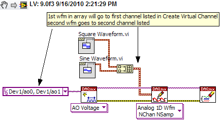
Using Labview and PXI-4461, how can I AO0 output Signal Square and AO1 output waveform
I am using PXI-4461 and Labview, boredom, generating 2 signals simultaneously.
How can I get AO0 out square and exit AO1 SignWave?
Help, please. (The example Code would be nice)
Thank you.
Create two signals and make a table with them. Use DAQmx Create Virtual Channel to create two channels. First waveform will be sent to the first string, second waveform on the second channel.
I understand not all as calendar, clock frequency, amplitude, trigger and other parameters. You can add these things. This is just a basic example.
-
Use the PXI-2630 terminal block in a matrix configuration?
My apologies in advance for the length of this post!

I use the PXI system with PXI-2530 switch modules, related to a series of USE with PXI-2632 (1W matrix 8 X 16) connector blocks and a PXI-4071 DMM for each switch module. My request, uses the PXI system for measurement of current and voltage external to verify and/or benefit from restraints of reliability. A requirement of the application, therefore, is that there must be a ride from DC through each USE with change of the minimum impedance as the application between its "bypass" mode switches and its mode 'measure '.
I used this Setup with connector blocks of matrix in conjunction with one of our test systems, and I am satisfied with the results. I started working with the Test System, has no easy connection to catch HAD, I needed to build a kind of interface the PXI system and a resistive faced load HAD, it was not difficult to build in the wires that attach to the Terminal screw of the 2632. He did turn into a nest of a coded son rat I did my best to keep clean and tidy in different bundles, however. Fortunately for the cable fasteners!
My next task is to use this application with system B Test, which has an interface of pines buck header with which each signal that goes to or from the DUT can be obtained. No welding or pass the wires through the openings where the designers have no intention of son to be stuffed. I intend to build a break-out Board that allows simple connections between the modules PXI and the number of Test B system which we have or will have in our laboratory. In order to simplify the configuration/installation, I want to reduce the number of connections to terminal block screw. Preferably, I would like to completely remove the screw terminals and use lever-based connections where I can't have mating of the headers. The PXI-2632 terminal blocks unfortunately use Terminal screw.
In matrix mode 8 X 16, the closing of the PXI-2530 switch kcom1, 3, 5, 7, no matter what points in the array are connected. A link between the row of right and column C is done by closing the switch corresponding to k (16R-C). I checked using the Soft Front Panel.
I also have a number of connector PXI-2630 blocks. These are intended to be used with the switch module in one of its MUX modes and include 8 banks of connections of the header 2 X 9 pins. In the the 2530 documentation and 2630, I identified that switch k-x is associated to chX output pin, ch0-15 related to the pins 1-16 from Bank 0, C16 - 31-associated pins 1-16 of Bank 1, etc.. X = 16 B + P-1. PIN 18 of each bank is used for independent MUX topology comX. Pines multiplexes sixteen seem to correspond to the sixteen columns of the matrix, with eight common lines corresponding to eight lines.
Here's what I would do, but I would like to ping the forum to see if anyone tried something similar and wisdon to share the thought:
- Make custom cables which connect the pins 1-16 of all eight banks 2630's header with a single Ribbon connections 16 son carrying the signals emitted by the interconnected banks (poles!).
- The custom cable bundle will also include a wire connected to the pin18 of each of the eight banks (line connections!)
- 24 total wires in the harness will end in the header connections who will probably partner by the lines that I currently connect to each object to be measured.
- Make additional harnesses that interface with the Test System B header pins.
- Make a map of derivation using band Council or a similar material to provide header pins to connect the two above custom cables and allow the connection of other elements such as resistors using Terminal level.
I checked this concept using the Assembly of 176 pins four terminals, like a bunch of little pieces of wire and cable. Are there other issues that I have to configure, such as the elements of a terminal that establish physical components of the switching topologies? The bowels of the PXI-2632 provide more features than the interconnection of the sets of eight sixteen pins? The bowels of the PXI-2630 connect elements that do not allow my proposed scheme?
I appreciate the suggestions and all entries!
Thank you
Jeff Zola
Hi Jeff,
First a correction to my previous post: 2632 Terminal has no reed relay protection resistors as I said earlier. The resistance that you were referring to the 2632 and those that I confused, is there to connect the columns of the switch. Resistances have a resistance value zero and act as the electrical connections. The 2632 connects columns c0 to c16, c17 c1, c2 to c18 and so on. Switch cards 2531 and 2532 have the protection relay reed on board resistors.
As for resistance in the map that protect the reed relays, they are generally very low and do not significatly affect even small tensions that pass through the switch. The resistance won't affect all currents in the map. Any effect that the resistors have on tensions will be with the precision of the switch card specifications.
Thus, to address the other issue in your post, there is no resistance in the connectors because they are not necessary.
-
Time-out error when you try to calibrate a PXI-6552 using Calibration Executive.
I make a mistake I never saw elsewhere trying to calibrate a PXI-6552 using Calibration Executive. We have been calibrating these cards for 3 years and never had a problem. The error I get has to do with the HP 3458 A DMM taking a reading.
1074126845 error occurred at IviDMM Read.vi in audit generation step voltage
The possible reasons: maximum time state of the driver (Hex 0xBFFA2003) exceeded before the operation is complete.
The primary error: (Hex 0xBFFF0015) timeout expired before the operation is complete.As soon as Cal Exec implements the PXI-6552 module then will take a reading of the 3458A what an SRQ message on the 3458A, then the error message above appears in Cal Exec. I tried to reinstall the drivers OR DMM. The voltage on the meter screen is good for the first stage (5.5 volts DC), but it times out and gives me the error as indicated.
Nevermind, I got the latest drivers and install and everything works fine now.
-
How to find out what the police are actually using Firefox?
How to find out what the police are actually using Firefox?
Inspect the element don't say what substitute fonts.Firefox 24 ESR has the tab fonts in the Inspector, which shouldn't be a problem.
-
I can not set the options, use my window and tags from yesterday, because it is grayed out! I could not find why it would be gray.
I keep 5 tabs open all the time and it becomes a pain to have to reset the all bookmarks, each time firefox is closed and reopened. just because I can't put to do so in the options, because the selection is grayed out in the options
Because you're probably using private browsing, go to tool > > privacy > > will Firefox option: change to remember history, now you can change this option "When Firefox Start" to "show my windows and tabs from last time.
-
Question
I can't get the tabs of the previous session of the return when I reopen it Firefox. I tried closing with 'Close' header of Firefox window, but also 'Quit' in the file Menu. Note that "Restoration of previous Session" on my Menu history is grayed out so I can't use it. In addition, there is no tab at the top of my window to open Firefox Firefox - only a menu bar that shows "File", "Edit", "View", "History", "Favorites", "Tools" and "Help". I am running Windows 7 Home Professional and Firefox 4.01"I can't do the tabs from the previous session of the return when I reopen it Firefox.
Remember that you are not private browsing or they are in permanent private browsing mode. See: https://support.mozilla.com/en-US/kb/Private%20Browsing (2nd and 3rd options menu on this page)
Make sure that you are not clearing history during a session or when Firefox is closed. See:
- Clear recent history: https://support.mozilla.com/en-US/kb/Clear%20Recent%20History
- Clear history of Firefox closing: uncheck 'Clear history of Firefox closing' options > Privacy panel (the first item under "History" on this Panel should be set on "Firefox will be: use the custom settings for history" to see that point to uncheck)
"There is no Firefox tab at the top of my Firefox window open - only a menu bar.
The Firefox button is supposed to be on by default in Vista and Windows 7.
In Firefox 4, you have the choice of using the Firefox (orange or grey) button in the upper left or the menu bar (File, Edit, View, history, Favorites, tools.) Help).
- The selections on the Firefox button are distinguished by the menu bar options.
- You can easily switch between the Menu bar and the Firefox button or leave one or the other active.
- One used depends on if the Menu bar is enabled
- Bar menu checked = Bar Menu on, Firefox off button
- Bar menu unchecked = Menu Bar off, Firefox button on
When the Firefox button appears and you want to temporarily view and use the menu bar, press ALT or F10 displays the menu bar and you can make your selections in the Menu bar displayed temporarily.
To check (or uncheck) the menu bar, do one of the following:
- using the Firefox button: click on the Firefox button > Options > Menu bar
- using the Menu bar: click on view > toolbars > Menu bar
- Hold DOWN the ALT key while pressing the VTM keyboard letters
Maybe you are looking for
-
Simultaneous connect via Dock and via Bluetooth?
Forgive the newbie question, but I use my Iphone6 to connect to my stereo system through a dock and also want to connect via Bluetooth to a speaker in a room? This can be done? Thank you!
-
Equium A200-1VO displays a CD drive (d) and a dvd player (e :))
Hello I have a little problem. My A200-1VO shows 2 discs. When I click on the D: drive, it says please insert disc always and if I click on eject said drive in use, even if the drive does not exist. Drive F is the real player and works properly.Anyon
-
Lost apps and singing and games on I phone4
Accidentally reset factory settings on my I phone4 while trying to trade tips between phone and laptop. I wonder how too get by them? There was a lot of money down the drain, I thought? I hope not? :-)
-
How to remove all the HP back in a MS241a
Is there a sheet of instructions anywhere on how the back detaches the HP all in one single MS241a... .exposing the card mother etc... Thank you
-
unique relaxation of waveform transmissions
Hi all I am trying to capture a waveform edge rigsing. Tecktronics drivers have no unique relaxation. Is it possible that I can do a single trigger, and then save the savefrom on the screen. A digital I/o is used to control a converter to generate an