output analog dc offset
When I use the example of the expedition:
'Cont Gen tension Wmf - Ext Clk.vi' I get the out waveform on the analog channel without problem. When I stop the vi there is always a level 3 of VCC on my output string. This isn't there until after I have stop waveform generation.
W that happens any AO channel.
LabVIEW 2009
PXI6723
First of all, I would like to use the task to stop DAQmx to stop the acquisition. If she is not reset that, write an acutal 0 to all channels. These two must be made before the task is disabled.
Tags: NI Software
Similar Questions
-
Outputs analog USB-6211 won't go below 3.375V
I use a 6211 to pulse output 0 - 5V outputs analog using an external clock as a trigger, and after successfully using the system for a while I finished with a question where none of the channels AO out lower voltages at 3.375V. My current theory is that I can have exceeded the current 2mA max output, but I don't know how, which would result in what seems to be a permanent tension.
I have reset the device and tried using other computers, but the problem remains. I ran the diagnostic utility and it fails part AO when it tries to output 0V and reads the 3V but he gave no further information. All other parts of the diagnosis are very good.
Any help would be appreciated, I'm a little stuck on my diagnosis.
Hi Airgunner1,
I'm not quite sure because I've never worked this side of the process, but if you call in they should be able to tell what your options are. Sorry I can't be more helpful!
-
rate real output analog OR-6351
Hello
I am trying to create a generator of arbitrary signals on both channels DAC on a NOR-6351.
Everything works fine - with the exception of the fact that I'm not sure what is the real rate of analog output.
This is quite crucial for me, I have calculate my wave based on Fourier transformation fast discrete - to get the correct frequency, so it is important to know the rate of real output.
The card has a rate of update AO 2.86MS / s,. The property timing - real sample clock frequency product also these 2.86 MHz.
When I then try to use the same frequency to generate two analog outputs, it always tells me that it uses 2, 86 MHz, even though the notebook loads says only he can produce 2 ms/s when using two channels.
So my question is, how to determine the actual flow of outputs analog?
And what is the rate of real output of the DAC?
Concerning
Jørgen
I just had a scope attached, while generating a sine function at 300 kHz, the rate of 2.86MS / s.
The scope read 300 kHz, which must mean that the DAC will actually to 2.86MS / s, otherwise the resulting waveform would have been to close to 200 kHz.
I have this will mark it as resolved, although I have not yet crazy understand why it is able to output at this frequency.
-
Producer consumer with inputs and outputs analog and digital
Hello world
I'm working on a program of control system for some practical test work. Currently, I am working on the data acquisition of the Labview program component. My architecture is consumer-product loops with a what. My system will have analog inputs, outputs, analog inputs and digital outputs. It is not a criticism of time sytem, but I wish that all the acquisition of data to synchronize. I enclose my program because it is at the moment. I have difficulties to get all the data in the since that I have two types of data. In addition, I don't know if I have synced the four sequences of read/write correctly. I would be very happy if someone could take a look at my program and give me some advice. Thanks in advance.
-
How to trigger and outputs analog and digital Outout tasks begins on a counter to start?
Hello
I'm trying to synchronize the start of a task outputs analog, a task of digital output and a task of counter. I want to start the counter to serve the master trigger and analog and digital tasks to synchronize his departure.
I guess I need something like:
analogOutputTask.Triggers.StartTrigger.ConfigureDigitalEdgeTrigger ("?", DigitalEdgeStartTriggerEdge.Rising);
digitalOutputTask.Triggers.StartTrigger.ConfigureDigitalEdgeTrigger ("?", DigitalEdgeStartTriggerEdge.Rising);
analogOutputTask.Start (); Slave 1
digitalOutputTask.Start (); slave 2
() counterTask.Start; n / / master
Where? is a string specifying a command source for the beginning of the task of the meter. However, I can't find what this string. Any suggestions?
Thank you!
-Jon
Just FYI, the solution to this problem as well as some other ones is encapsulated in a short example .NET, I created. It is on the Web site of EITHER:
http://decibel.NI.com/content/docs/doc-15500
This project shows how to synchronize all your analogue/digital outputs through tasks and forums in terms of synchronizing Calendar and start clock.
-Jon
-
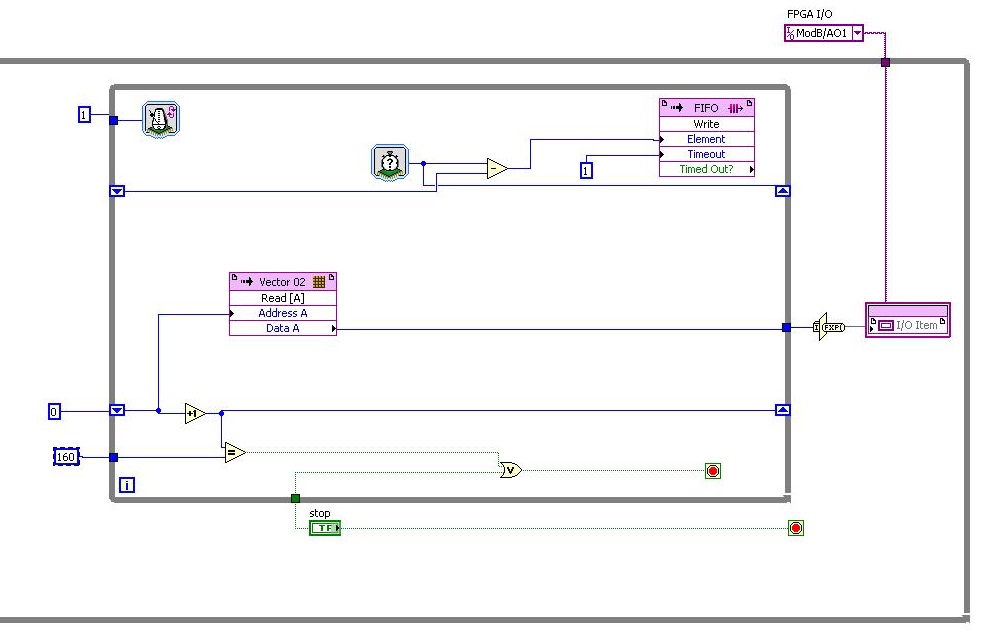
FPGA output analog fastest? (RIO 9641)
Hello world!
I read only analog output have about 38 tics. clock 40 MHz (RIO 9641)
My RIO gives me tics 107 = 112 - 5 analog outputs for the 1 iteration. If DAC cycle... The entire cycle takes (112 * 160 * 25th-9) for DAC 107 * 160 * 25th-9 = 428e-3 s always takes DAC, and I need more quickly.
How to set up outputs analog faster or rebuild program?I need the fastest analog output, is it possible?
Thanks for the help!
Hi togoto,.
Please let me know if I'm struggling to understand what you're trying to do, but the fastest, the analog output of the 9641 can update is 120 ticks by update. Which is based on the specification of the material on page 44 of the User Guide and the restriction that you touch. Therefore, I don't think you'll be able to get it down to 40 ticks.
-
Output analog, the USB-6009 case - can I use DAQmxWriteAnalogScalarF64?
I just got a NI USB-6009 and I try to use the outputs analog simple.
I'm running on a Mac, so I'll try to use the API OR-DAQmx Base 3.2 C (downloaded from here: http://joule.ni.com/nidu/cds/view/p/id/1078/lang/en). This is the most recent version of NOR-DAQmxBase, I could find.
I try to do continuous analog output on the 6009, which does not have a built-in clock. I was hoping to do the sync software and just new output values when I want to.
I can't get an output of database to work. Other messages and the example of Windows files, (e.g., National Instruments/NOR-DAQmx Base/examples/ao/MultVoltUpates-SWTimed.c) it seems that the best thing to do would be to use the DAQmxWriteAnalogScalarF64 function.
However, this is not in the Mac version of the C API of NIDAQmxBase. There is actually an entry for this in the NIDAQmxBase.h file, but it is commented out. Anyone know why? Is it possible to use this function for the analog output on request on Mac?
Thank you.
Clement
I have NEITHER-DAQmx Base installed 3.2 on a 10.4.11 system. One of the examples files 'genVoltage.c' calls DAQmxBaseWriteAnalogF64. I was able to compile and run this example with a USB-6009.
The DAQmxBaseWriteAnalogF64 function would work for you?
My guess is that, since you can write a scalar value with DAQmxBaseWriteAnalogF64, DAQmxBaseWriteAnalogScalarF64 becomes superfluous. The example provided with the installation shows how to write a unique value (i.e. scalar.). I pasted the code of OR below.
int main (int argc, char * argv [])
{
Task settings
Int32 error = 0;
TaskHandle taskHandle = 0;
char errBuff [2048] = {'\0'};
Channel settings
Char [] = "Dev1/ao0" chan
float64 min = 0.0;
float64 max = 5.0;
Sync settings
uInt64 samplesPerChan = 1;
Writing data parameters
float64 data = 3.25;
pointsWritten of Int32;
float64 timeout = 10.0;
DAQmxErrChk (DAQmxBaseCreateTask("",&taskHandle));
DAQmxErrChk (DAQmxBaseCreateAOVoltageChan(taskHandle,chan,"",min,max,DAQmx_Val_Volts,));
DAQmxErrChk (DAQmxBaseStartTask (taskHandle));
DAQmxErrChk (DAQmxBaseWriteAnalogF64(taskHandle,samplesPerChan,0,timeout,DAQmx_Val_GroupByChannel,&data,&pointsWritten,));
Error:
If (DAQmxFailed (error))
DAQmxBaseGetExtendedErrorInfo (errBuff, 2048);
If (taskHandle! = 0) {}
DAQmxBaseStopTask (taskHandle);
DAQmxBaseClearTask (taskHandle);
}
If (DAQmxFailed (error))
printf ("error in DAQmxBase: %s\n",errBuff); ")
return 0;
}
Hope this helps!
-
regeneration of the outputs analog
Hello
I am writing a program to fight mirrors laser. I use the example: output - analog continuous regeneration No. When I put a counter on since the while loop itteration, I can see I runs very fast for the first 10 hours, and then it slows down to normal pase... Is it possible to make the VI that it doen'st run so fast in the first round? Looks like that it is buffering a whole bunch of data... But I want to pause from time to time the exit...
Best regards
Thijs
-
Integrate the outputs analog with analog inputs
I have a program that displays 2 analog output waves and a separate program that captures the analog data through several materials of NEITHER. I need to integrate the program outputs analog in my analog input program.
The program of analog output is fixed as "AO_Triggers_LowLevel.vi" and the analog input is fixed as "ExperimentDAQ.vi". When I try and integrate these programs I get 'error-200560 occurred at DAQmx waiting until the Done.vi' to my function to wait until it makes my task of analog input (background of the program). I think it is my mistake in the order that I'm wiring to the top of my son of error but I'm not sure. I watched several tutorials (Timing and synchronization features of DAQmx) but I'm totally stuck.
Any suggestions are greatly appreciated. Thank you!
Alberto M.
I think I've fixed this problem. I extended my flat sequence structure to include the lines of task and error of my task outputs analog and things seem to work. I'm still not sure about what caused my error and why it has solved the problem...
-
Tecra S3 Advanced Port Replicator III more: video output, analog & digital
I have a Tecra S3 in association with Advanced Port Replicator III.
I can't get the two graphics cards to work together.The analog and digital video output should work together.
It works on a Tecra S2, but not on the S3?
Does anyone have an answer?Hello
You want to use both outputs DVI and VGA on Advanced Port Replicator III graphics more simultaneously?
Advanced Port Replicator III more supports the use only if the computer system unit laptop itself also supports the simultaneous use of RGB & DVI.
So that would mean that the backs of Tecra S3 not supported this feature
-
Performance outputs analog 4461
I'm generating a sine wave of 1 kHz to 1.5V waveform DC offset and 800mVp. I use this signal to test a 12 bit ADC. As indicated in the attachment the best I can get is - 70dB on the second harmonic, which is to be able to test only a system of 11 bits. I need better that - 75db on the 2nd harmonic. I use the output in an active probe impedance high through a HP being a 24-bit DAC I thought that it would be able to perform this task. What Miss me? I've also attached the LabVIEW code that I use.
John
-
Hello
I'm new to LabWindows, and now I have a question.
I would like to generate the same signal on two analog outputs (SCB-68). My Code is this:
/*********************************************/
DAQmx Configure Code
/*********************************************/
Channel 1
DAQmxCreateTask("",&taskHandleCH1);
DAQmxCreateAOVoltageChan(taskHandleCH1,"Dev1/ao0","",-10.0,10.0,DAQmx_Val_Volts,NULL);
DAQmxCfgSampClkTiming(taskHandleCH1,"",1000.0,DAQmx_Val_Rising,DAQmx_Val_ContSamps,1000);
Channel 2
DAQmxCreateTask("",&taskHandleCH2);
DAQmxCreateAOVoltageChan (taskHandleCH2, ' Dev1/ao1', ' ',-10,0, 10.0, DAQmx_Val_Volts, NULL);
DAQmxCfgSampClkTiming(taskHandleCH2,"",1000.0,DAQmx_Val_Rising,DAQmx_Val_ContSamps,1000);/*********************************************/
DAQmx write code
/*********************************************/
Channel 1
DAQmxWriteAnalogF64 (taskHandleCH1, totalPulseSizeCH1, 0, 10.0, DAQmx_Val_GroupByChannel,)
PulsePatternCH1, NULL, NULL);
Channel 2
DAQmxWriteAnalogF64 (taskHandleCH2, totalPulseSizeCH2, 0, 10.0, DAQmx_Val_GroupByChannel,)
PulsePatternCH2, NULL, NULL); * //*********************************************/
Starting code DAQmx
/*********************************************/
DAQmxStartTask (taskHandleCH1);
DAQmxStartTask (taskHandleCH2);But the program did not run. I got the failure:
NO MORTALS RUN - TIME ERROR: "Test.c", line 175, col 13, id 0 x thread 00001328: DAQmxWriteAnalogF64 function: (return is 50103 value [0xffff3c49]). The specified resource is reserved. The operation could not be performed as indicated. Task name: _unnamedTask<1> Code of State:-50103
I think the default is 'DAQmx_Val_GroupByChannel', I mean that both write controls use the DAQmx_Val_GroupByChannel at the same time so I can't use the second write command because one uses alreay. But I don't know if it's okay.
Can sombody help me please to solve the problem?
Best regards
It is correct to double the buffer and fill it with the appropriate model. DAQmx reads the buffer and splits between the channes trends according to the layout of data in DAQmxWriteAnalogF64 () setting. If this parameter is set to channel group, samples for a channel are stored consecutively, followed by samples for the following string and so on, as you did so far; If number of sweep of groups, the samples are stored interlaced, i.e. (assuming N and M samples per channel channels): Channel1Sample1, Channel2Sample1... ChannelNSample1, Channel1Sample2... ChannelNSample2... Channel1SampleM... ChannelNSampleM.
If you want to have Different patterns on the channels, please fill the buffer with different data tables.
-
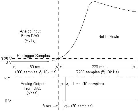
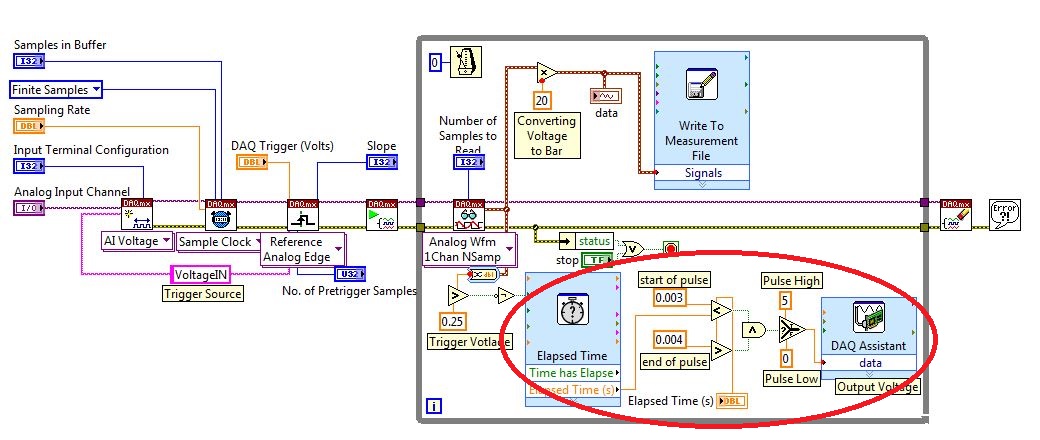
I am working with a combustion chamber and using a system of data acquisition (with the hardware OR SCB - 68) to read the pressure in the cylinder (such as analog voltage). I'm trying a pulse delayed, 1 millisecond to 5 volts of output once the pressure in the cylinder is high above 5 bar (which corresponds to an analogue voltage of 0.25 V). I would also like to record 30 ms samples before the trigger and 220 ms samples after the outbreak. The following image shows visually what I'm talking about.
I created a LabVIEW VI (which is attached), but I keep running into 2 issues:
- When I run with samples finished after a period of time, I get error-200281which I don't quite understand.
- Using the Express VI 'Out of time' to keep time for the pulse I can not get a resolution of 1 millisecond, the pulse is not generated when I put the window between 0.003 and 0.004 seconds for high pulse (i.e. the resolution of 'Elapsed Time' seems to be too coarse).
I'm a beginner to LabVIEW sorry if my questions are trivial or my VI makes no sense, but I was stuck on this during more than a week. Any help would be greatly appreciated!
Thank you
Morgen
This isn't a good way to trigger a pulse.
Use a trigger DAQmx to send the pulse when your acquired signal exceeds 250 mV you specified.See this for DAQmx trigger:
-
Interleaving of samples: two outputs analog (tables with different lengths)
CHAN                   AOCHANNEL1       AOCHANNEL2       AOCHANNEL1           AOCHANNEL2       .. .and so on
SAMP                   * * * * *           *              * * * * *              *           .............and so on
Hi guys, how could I go on the interlacing of two arrays of different lengths in a two-channel analog output?
In the illustration above, for example, I like to write 5 values in channel 1, followed a string of unique value 2 and so on...
I use DAQmx library controls to achieve this (not LabView).
I am able to write unique values each time a task is opened without any problem, I was wondering if I can interleave the berries so that values are buffered and tasks are performed with greater haste.
best regards,
Ravi
target met: I've made the following changes:
CREATION OF TASK 1
CREATION ANALOG_VO channel 1 & channel 2 in TASK 1
CONFIG. CALENDAR OF TASK 1CREATED some TENSION with SAMPLES interleaved pre
WRITING TASK 1 VALUES
TASK 1 STARTED
DAQmxCfgSampClkTiming(taskHandle1,"",SAMPLING_RATE,DAQmx_Val_Rising,DAQmx_Val_FiniteSamps,2*SAMPLE_SIZE_WX) -
USB-6009 software simultaneous timed output analog
Ladies and gentlemen,
I worked on a LabVIEW interface to a potentiostat I designed and built. I'm not very experienced with LabVIEW, but do they have experience with a variety of other languages (I had originally intend to use an FPGA for this, but he has been asked to write a LabVIEW VI first) programming.
The goal:
I want to output a voltage (initially consisting of ramps) signal and measure the voltage with an operational amplifier configured as an ammeter of feedback (using resistance feedback and voltage value to calculate current) connected to an electrochemical cell. The resistance of feedback is selected by using an automatic selection function (although I wrote a version prior to manual control) as TTL values using the DAQ Assistant to select relevant MUX channel outputs. I then try to save the data in a spreadsheet.
The problem:
I use an acquisition of data USB-6009, and I know that there is a hardware clock. Read all about him seemed obvious, the best way to the waveform of the output voltage used DAQmx package to define a function of writing in a loop that is clocked by the software. The problem I have is that I can't synchronize the output to the input with reliability and I have also some errors related to resources DAQ being reserved (error 50103). I think the way to solve this would be to convert every equivalent DAQmx DAQ Assistant and try to group their execution - this is where I fall. I tried to write a simple VI who shared a loop clocked by the software to read and write but had problems related to the value of min HAVE (error 200077).
General issues:
How I begin the process of read/write (with a Boolean switch) is very weak and doesn't feel not robust. Ideally, I would like to some form of indicator to warn the user when the read/write process is running and when it ended.
My error handling is terrible, but I find no big thing to read about the basics.
I use only a sequence of no and I think I should have more.
Once I hit the beginning, VI requires the file name for the worksheet - at first, I was afraid that data would be entered correctly, but I think it's okay because the file is generated and then changed. It would be better if the user asked for the name of the file once completed the data collection.
Any suggestion or help would be greatly appreciated. Thank you in advance.
Sincere greetings,
Julius
The hardware supports timed 6009 entry analog. Even with the 1Samp mode, your code could be simplified with a single task and several channels (dev1\ai0:1). Then use Nchan 1Samp.
Maybe you are looking for
-
After that update of windows 64 bit system Firefox does not start
I've updated to IE 10 and it should be updated to complete. My preference is Firefox, but it does not start and produces an error box telling me that Firefox could not start, it also sends you a report of failure.It happened in a previous windows upd
-
Could not find the update of BIOS for my Tecra A8
Hello I have my laptop Tecra A8 PTA83E-0FJ05DJK and I want to update its BIOS, but in a page Web updated BIOS of TOSHIBA, there is no update for my laptop. How should I do?
-
Need to find a driver for NETWORK card for my P7-1010
I had a few difficulties to connect to my cable company and they said that it's maybe because I didn't install the necessary NETWORK card driver. That sounds wrong and if so, where can I find 'he'... or all the other drivers, I may need. Is there a c
-
Cable manufacturer Req'd for a PE 430 w / Mono Mini H330
Hello We are trying to install a PERC H330 Mono on our server PowerEdge R430 Mini card. He came with a cable that fits on the mini map mono (photo 1) but has a cable that connects the 90 degrees of the clamp (photo 2). We need a cable that has the bu
-
Access to the Java applications to a camera on BlackBerry
A java application developed by we would need to interact with the camera of BlackBerry devices. I would appreciate to know if this is possible and if so, with the terminals and the versions of the operating system it would work. Thanks in advance. A