Outputs analog USB-6211 won't go below 3.375V
I use a 6211 to pulse output 0 - 5V outputs analog using an external clock as a trigger, and after successfully using the system for a while I finished with a question where none of the channels AO out lower voltages at 3.375V. My current theory is that I can have exceeded the current 2mA max output, but I don't know how, which would result in what seems to be a permanent tension.
I have reset the device and tried using other computers, but the problem remains. I ran the diagnostic utility and it fails part AO when it tries to output 0V and reads the 3V but he gave no further information. All other parts of the diagnosis are very good.
Any help would be appreciated, I'm a little stuck on my diagnosis.
Hi Airgunner1,
I'm not quite sure because I've never worked this side of the process, but if you call in they should be able to tell what your options are. Sorry I can't be more helpful!
Tags: NI Hardware
Similar Questions
-
Strange analog output of USB-6211
I just got USB-6211 to replace USB-6001 to set the clock to external sampling on analog output for LED lighting control. The part of external clock example works fine, but the analog output voltage is strange. To do self-monitoring, I connected control pin LED to AO0 & AI0 of surveillance in the NI MAX test panel and LED control on the ground at AO - GND & GND HAVE since I have both USB-6001 and USB-6211, I conducted tests on two of them with the same setting of wire. When I generate sine wave - 5V to 5V to AO0 (from NI MAX test panel), USB-6001 can monitor the same signal AI0, but watch USB-6211 - 3, 4V to 3.4V voltage truncated. I did the test separately (wiring one device at a time), so there is no interference between the two devices. USB-6211 past self-calibration and self-monitoring. Also, I did reset devices. I don't know why they would behave differently with the same configuration, and I hope that someone could help with this question. Thank you.
Hi skuo1008,
The USB-6001 can support + / 5 output current my from terminals to analog output, while the USB-6211 box can provide only +/-2 my current output. It is likely that the load impedance is too low, causing the 6211 to hit its current compliance and thus cut the tension. If you try to exchange your load with a resistance of at least 5 v/.002A = 2500 Ohms, you should be able to see the full +/-5V sine wave. I suspect that your DUT has a words 3.4V/.002A = 1700 Ohms impedance. You could use a device with higher output current or use a more current source buffer circuit. If you do not need a bipolar output, you might also consider using digital lines to control the LEDs.
Kind regards
-
Digital magnification of output using USB-6211
Hello
I'm trying to use the example of LV "Cont writing dig port - Int clk.vi" to generate a model.
But I get the error-200077 on the sample clock. The popup error message suggests
using "we demand", but it doesn't have the choice with the DAQmx.
Any clue? Thank you.
It is correct. USB-6211 case doesn't have a digital time - analog base only. That's why the (63xx) X series cards are supported only for this example.
-
Current limit for analog output on USB-6211-OEM
The current output drive listed in the specifications of this card is of +/-2 my. What happens when you try to go beyond that? Is there damage to the card or is it simply rail out around 2mA. For example, if I connect a 1000 ohm load. I'm okay, if I have the output up to 2V (= 2mA), but what happens when I exit 3V with the same 1000 ohm load?
Thank you.
Protection of the overdrive is 2.4 mA, which means that you can ride this current without damaging the card, but a current of approximately 2 mA, tension is more guaranteed to be compliant to the specifications.
Kind regards
Brian P
-
How stable is the long term outputs analog USB-6008?
The USB-6008 datasheet do not specify the stability long term of the analog inputs and outputs.
I'm looking for stability compared to the ambient temperature and time (several months to a year), mainly for the outputs or the D/A reference voltage.
Is there any information available?
Thank you.
The precision specification takes into account the evolution both because of the temperature and duration (stable). Thus, for the period of a year that we guarantee these specifications, which list you is correct. However, apart from the period of one year since the calibration, this specification may be is more inaccurate.
-
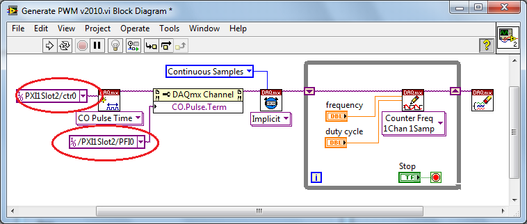
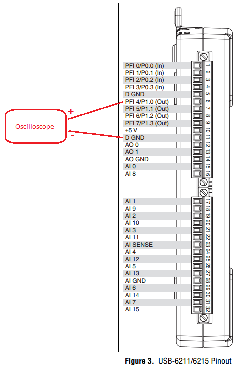
PWM - output meter (PFI4) USB-6211
I managed to control a motor based on PWM signal output via USB-6211 AO continuous. Now, I'm trying to use the Terminal counter instead.
Can't seem to make it work. NA not get a signal when link the PFI4 terminal to an oscilloscope.
I don't know wheather my coding is wrong or does not have my wiring (i.e. of USB-6211 for motor continuous). I need to use the terminal of meter that I used the analog output to a different measure.
Please advice. Attached encodings.
Thank you very much.
Front of conneting to DC motor, make sure first that the PWM is get generated correctly... use oscilloscope.
And have you changed the constant (physical terminals) for your device...?
Change to:
Dev1/ctr0 & Dev1/PFI4 and the scheme of connection must be:
-
Output analog, the USB-6009 case - can I use DAQmxWriteAnalogScalarF64?
I just got a NI USB-6009 and I try to use the outputs analog simple.
I'm running on a Mac, so I'll try to use the API OR-DAQmx Base 3.2 C (downloaded from here: http://joule.ni.com/nidu/cds/view/p/id/1078/lang/en). This is the most recent version of NOR-DAQmxBase, I could find.
I try to do continuous analog output on the 6009, which does not have a built-in clock. I was hoping to do the sync software and just new output values when I want to.
I can't get an output of database to work. Other messages and the example of Windows files, (e.g., National Instruments/NOR-DAQmx Base/examples/ao/MultVoltUpates-SWTimed.c) it seems that the best thing to do would be to use the DAQmxWriteAnalogScalarF64 function.
However, this is not in the Mac version of the C API of NIDAQmxBase. There is actually an entry for this in the NIDAQmxBase.h file, but it is commented out. Anyone know why? Is it possible to use this function for the analog output on request on Mac?
Thank you.
Clement
I have NEITHER-DAQmx Base installed 3.2 on a 10.4.11 system. One of the examples files 'genVoltage.c' calls DAQmxBaseWriteAnalogF64. I was able to compile and run this example with a USB-6009.
The DAQmxBaseWriteAnalogF64 function would work for you?
My guess is that, since you can write a scalar value with DAQmxBaseWriteAnalogF64, DAQmxBaseWriteAnalogScalarF64 becomes superfluous. The example provided with the installation shows how to write a unique value (i.e. scalar.). I pasted the code of OR below.
int main (int argc, char * argv [])
{
Task settings
Int32 error = 0;
TaskHandle taskHandle = 0;
char errBuff [2048] = {'\0'};
Channel settings
Char [] = "Dev1/ao0" chan
float64 min = 0.0;
float64 max = 5.0;
Sync settings
uInt64 samplesPerChan = 1;
Writing data parameters
float64 data = 3.25;
pointsWritten of Int32;
float64 timeout = 10.0;
DAQmxErrChk (DAQmxBaseCreateTask("",&taskHandle));
DAQmxErrChk (DAQmxBaseCreateAOVoltageChan(taskHandle,chan,"",min,max,DAQmx_Val_Volts,));
DAQmxErrChk (DAQmxBaseStartTask (taskHandle));
DAQmxErrChk (DAQmxBaseWriteAnalogF64(taskHandle,samplesPerChan,0,timeout,DAQmx_Val_GroupByChannel,&data,&pointsWritten,));
Error:
If (DAQmxFailed (error))
DAQmxBaseGetExtendedErrorInfo (errBuff, 2048);
If (taskHandle! = 0) {}
DAQmxBaseStopTask (taskHandle);
DAQmxBaseClearTask (taskHandle);
}
If (DAQmxFailed (error))
printf ("error in DAQmxBase: %s\n",errBuff); ")
return 0;
}
Hope this helps!
-
Sampling frequency for the output of an acquisition of data USB-6211 card?
Hello-
I use a CGI CMOS FireWire camera to read an interference figure, then using a transformed of Fourier transform spectral interferometery (FTSI) phase recovery simple algorithm to detect the relative phase between the successive shots. My camera has a linear 28 kHz scan rate, and I programmed my phase retrieval algorithm take ms ~0.7 (of a trigger of camera at the exit of the phase). I use the live signal to control a piezoelectric stack, by sending a voltage single sample to the analog output of a data USB-6211 acquisition card.
Send this output voltage increases the time of my loop 4 m, I would really like to achieve a 1 kHz or better sampling rate. Is the problem with my DAQ card or with the processor in my computer? The DAQ cards of NOR can support these speeds?
Thank you
-Mike Chini
Hey Mike,
With USB, your loop rate will be around or under 1 kHz, even on the best of the systems. USB has a higher latency and less determism PCI and PCIe. You can get rates AO one much better sample on a PCI card, potentially a PCI-6221. We have a few HAVE points of reference for targets of RT for PCI, / AO in a loop, you should be able to get similar performance in Windows, but if you do a lot other treatments may suffer from your local loop rates.
Hope this helps,
Andrew S
-
USB-6211 - digital output not supported?
Hi all
I can't use the USB6211 device port... I use daqmx with Delphi7 API functions.
First of all, I tried this:
DAQmxCreateTask('', @TaskDO);
DAQmxCreateDOChan (TaskDO, PChar('Dev1/port0'), ", DAQmx_Val_ChanForAllLines);
DAQmxWriteDigitalU8 (TaskDO, 1, 1, 1, DAQmx_Val_GroupByChannel, $FF, @written, nil);I had an error in the DAQmxWriteDigitalU8:-200012 (= digital output not supported). (???)
OK, I tried to disable autostart option based on DAQmxWriteDigitalU8 and insert a 'manual' start in the code:
DAQmxCreateTask('', @TaskDO);
DAQmxCreateDOChan (TaskDO, PChar('Dev1/port0'), ", DAQmx_Val_ChanForAllLines);
DAQmxStartTask (TaskDO);
DAQmxWriteDigitalU8 (TaskDO, 1, 0, 1, DAQmx_Val_GroupByChannel, $FF, @written, nil);
DAQmxStopTask (TaskDO);Now, I got the same error in DAQmxStartTask:-200012 (Digital Output not supported, once again). (?????)
I don't understand.. 'Digital output not supported "? USB-6211 has 4 lines! What is the problem?
I want to just turn on and off the lines from code...
-Cs George-
Well, finally I figured out...

Here is the solution:
DAQmxCreateTask('', @TaskDO);
DAQmxCreateDOChan (TaskDO, PChar('Dev1/port1'), ", DAQmx_Val_ChanForAllLines);
DAQmxWriteDigitalU8 (TaskDO, 1, @dummy, 1, DAQmx_Val_GroupByChannel, @bitmask, @written, nil);Digital output lines are on port1! Corrected parameter.
And the part of the interface of DAQmxWriteDigitalU8 had to be changed (in nidaqmx.pas).
I don't know why, but the AutoStart (dummy) parameter in the DAQmxWriteDigitalU8 function is ignored: function always starts task automatically, regardless of the value of autostart. But this isn't a problem for me.-Cs George-
-
My ic emits a milivolt signal constant 330 he won't go below
Hello
I have a problem. I also connected an above (AD594). and thermo couple and I am able voltage through NI USB-6009. I get the right result for greature the temprature of 33 degrees centi. but when the temprature becomes less than 33. My ic emits a milivolt signal constant 330 he won't go below. means can't measure only minimum temp 33 degree. my temperature is 20 degrees. How can I check temp less than 33 degrees?
Thanks for help
HERE'S THE ANSWER...

Thank you guys
-
Hello
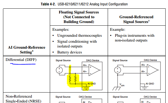
I use an NI USB-6211 device, Windows XP, and I have the problem of blood (photo attached).My analog differential signal (signal DC to DC power supply) is connected to an analog input in box usb-6211 (AI1 and AI9 ports).
The signal I get is evolving between 0V the Volt of entry (in the attached photo - 4V) instead of 4 v DC.
It might be a good idea to test it with a 9V battery using a differential connection with wiring configuration described in the manual (photo and link below). I know it sounds Basic, but re-seats black connector of i/o to the device might help. Make sure you reference GND AI as well.
-
Lack of charges, USB-6211 with linear gauge Mitutoyo (542 series)
I use a USB-6211 box with a race of 10mm Mitutoyo Linear Gage (542 series, model LGA-110). The Mitutoyo has output similar to an encoder without the time by rev signal quadrature. (B has a phase shift of 90 degrees of A). Signals A and B are airline pilots. I have a k 2 5V to A resistance and another 2K to 5V to B, gives me a minimum of 0.05v and a maximum of 4.75V.
The problem I encounter is that I seem to be missing certain counts that I can't always zero.
I found that if I caress the complete range of meter and the return to zero in 20 seconds, I get a value close to 180 meter microphone. If I press the complete range of meter and the return to zero quickly in a second, I get a value close to 800 micrometer.
If I caress the quick pledge on the compression and rebound more slowly, I find myself with a positive value. I caress the slow pledge on compression and quick on the rebound, I find myself with a negative value.
As I said before, it seems miss me certain counts. With a pulse of each mic of 4 meters, it means I get only 2500 pulses per 10mm. This means that 10mm per second is only 2500 pulses per second. It seems slow for me, so I don't know what would be the problem.
Does anyone have ideas for me to try?
With this type of signal you should not missing any counts. The time base on the box USB-6211 is 80 Mhz and therefore should have no problem to solve your two pulses per train. I have a couple of steps that I would like you to try troubleshooting.
1 to ensure that we plugged the inputs correctly to our DAQ hardware.
2 ensures that we use both the non-reversed or two signals reversed. Do NOT mix or 'type' of the signal.
3 allows you to wire signals A and B in two inputs analog and we will try to read signals to ensure that the sensor is actually be set correctly by the sensor. Be sure to taste pretty quickly--> 10 the frequency of the pulse train. If you race through 10 mm in 1 sec--> 2500 pulses per second--> 25 kHz sampling rate. Allows to check two things. First we have a good TTL signals, and that we get the right number of charges. If you reply to this thread plaese attach a screenshot of the present.
4. we will try different encoder types x 1, x 2, x 4 in the DAQ assistant. The x 2 and x 4 encoder allows the best sensitivity for small movements (which I'm not sure that it is the source of your proplem but it will be a good thing to check). Types of encoder are discussed in more detail in the following developer area: quadrature encoder measures: How To?
Let us know how it shapes to the top.
-
Can I use two USB 6211 to replace a USB-6009
Hello
I got a labview vi., 5 output channels digital, 2-channel digital input, 2 analog inputs are necessary for the execution of this vi. Initially a 6009 usb is used to run the vi. But I have only two usb ports 6211 now, which has digital to digital for each data acquisition 4 inputs and 4 outputs. I wonder, can I use two usb 6211 to run the vi. ? What should I do?
Reverse lines are wrong, does that mean it will display 0 for false and 5 V 1.
Active drive is the normal mode of the digital output: it generates tension when said.
I forgot one thing: that you are behind the wheel of these lines, how much power do you need?
Analog output is less powerful, it can give only 2-4 mA, while the digital output 6009 could give 8 my.
-
OR USB-6211 is used to count climbing on board TTL
Hello
I'm new to NOR-DAQ cards, and so before buying whatever it is would like to know if it is possible to use a device, NI USB-6211
County and bin amounting to edges of a TTL signal.
What I want to do is to count how many rising edges of a TTL signal I get in a period of 1 ms; a 20 Mhz sampling frequency should be fine.
I would like to use Matlab to control and read the number of edges that are counted as well as in the meantime write and read digital IO ports from the USB-6211.
Is it maybe possible to leave the external TTL signal trigger a 6211 counters, an output then periodically (1 ms) and reset the value of the counter?
Is it possible and if yes, is it a good idea?
Thanks and regards,
Manual
Manual Hi
In order to generate this signal, I could use a second timer mode continuous pulse Train generation, right?
-> Right. You can choose between 2 options
(1) get the signal to another device, for example signal generator or something like that. If you cannot use such a device, you must select the second solution->
(2) generate the 1ms period square wave with the meter of the USB-6211 seconds
I don't know a smart way to generate the 1ms period signal without the software side. You need the software to configure the second counter, route the signal to the second counter for the first counter and so on.
Maybe you can use what is called "panel test" inside the Explorer Measurment & Automation to generate signal. The Measurment & Automation Explorer is a tool provided with the driver for the DAQ cards. The original purpose of this software utility is to configure your hardware, test and so on.
I don't know if it works, but I imagine that the following solution:
You use the test panel called inside the Measurment & Automation Explorer to generate the 1ms period signal (see attached screenshot and http://www.ni.com/white-paper/4638/en). You have no additional program to run the test Panel. Box USB-6211, you use a wire to connect the signal output of the meter of second at the entrance to the first counter. After that, you run Control Panel to test the generation of signals for the seconds counter. At the same time, you start your Matlab program and configure only the first counter. You will need to run the Testpanel all the time if you want to run your measurment.
Not very nice, but maybe the only solution.
Best regards, Stephan
-
How I ouptut a digital waveform, it has collated and compare it to the original with a usb-6211 box?
I want a digital waveform to a circuit of output, read the return signal and compare the original to the read signal. I use a usb-6211 housing is it possible and if so, how?
Use a comparator "equals sign", mark the post as a solution if you have the makings of what you wanted.
Maybe you are looking for
-
Pavilion g-7: g-7-2269wm power on password
I see that you guys have been most useful in obtaining the different password reset, so I hope I have the same luck. Have a Pavilion G7 laptop and have lost the pop I tried several times and get the code 77788090 after 3 attempts. Please help me find
-
Hello How to get the double click event. (ex if I click table colume double time as only triger event.)
-
Recovery disks contradictory w / upgrade HP Envy 17 3D [HDD-> SSD]
Hey everybody! I have a HP ENVY 17 t - 1100 CTO 3D Edition laptop with Windows 7. He had two hard drives in it, 500 GB a piece. I just put the primary HDD with a SSD Samsung 840 Pro Series drive. Before I did the swap, I did recovery DVD from my syst
-
Hard drive Dell Latitude E4300
I have a question! What is the difference between the 200 GB hard disk (7200 RPM) free fall sensor and the fall sensor free 250 GB hard drive (7200 RPM), because the 200 GB version is 70 Euro more expensive than the 250 GB version. Are there differen
-
Hard drive 320 GB Seagate HDX X18T - 1200 CTO failure
Hello everyone. I bought my HDX X18T - 1200 CTO last summer with the option of two hard drives of 320. I currently have my secondary drive failed each test disk error checking I throw at it so I know it's meant to death in the imminent future. Questi