Output analog single shot: how this impulse. Probably easy, I am at a loss.
Hello.
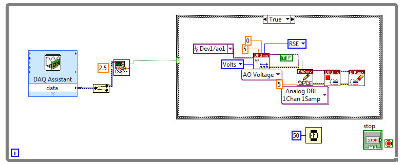
I have a piece of equipment connected to my system. Whenever it reaches a proximity sensor (it is a reciprocating machine), I need to make a single pulse of 5v out of my analog output. It must be fast, it should stop until the sensor is reached again, and he can't stay 'market' for a long time.
I have attached my VI. I use a power supply via the DAQ assistant, routed via a logic to produce a Boolean 'true' value whenever the sensor is reached and that boolean is connected to a structure dealing with tasks created in DAQmx voltage.
My problem is that the machine will not reverse while the case is always true, and there is still the 5v called by the real case on the structure of the case. Pulse, and then stop, be allowed to return when the proximity sensor is again reached. As it is now, the machine reaches the prox and then the whole system stops, as the condition of 'real' on the case structure and the subsequent voltage output, remain high.
I have attached the VI and the hierarchy as well.
I tried a few different things here, as everything using a DAQ assistant with samples of N, but that would be just retrigger when the loop repeats itself in any case.
I'd love to sit and bang my head against this until I understand, but I am under a time constraint. Help!
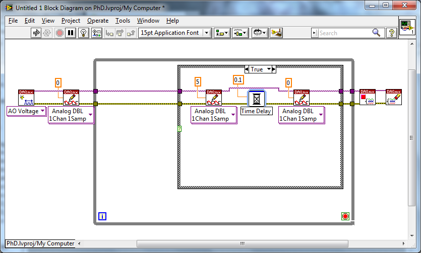
Try something like that. Set the input to the function of "Delay" for however long you want your pulse to be (within reasonable limits). You have not specified a value of "fast". I initialize your line of analog output 0... It's a good idea, but it's up to you if you want to do it or not.
Tags: NI Software
Similar Questions
-
How to trigger and outputs analog and digital Outout tasks begins on a counter to start?
Hello
I'm trying to synchronize the start of a task outputs analog, a task of digital output and a task of counter. I want to start the counter to serve the master trigger and analog and digital tasks to synchronize his departure.
I guess I need something like:
analogOutputTask.Triggers.StartTrigger.ConfigureDigitalEdgeTrigger ("?", DigitalEdgeStartTriggerEdge.Rising);
digitalOutputTask.Triggers.StartTrigger.ConfigureDigitalEdgeTrigger ("?", DigitalEdgeStartTriggerEdge.Rising);
analogOutputTask.Start (); Slave 1
digitalOutputTask.Start (); slave 2
() counterTask.Start; n / / master
Where? is a string specifying a command source for the beginning of the task of the meter. However, I can't find what this string. Any suggestions?
Thank you!
-Jon
Just FYI, the solution to this problem as well as some other ones is encapsulated in a short example .NET, I created. It is on the Web site of EITHER:
http://decibel.NI.com/content/docs/doc-15500
This project shows how to synchronize all your analogue/digital outputs through tasks and forums in terms of synchronizing Calendar and start clock.
-Jon
-
How do I get the analog input signal and send it to output analog (real time)
Hello world
I do a simple task in Visual C++ and I use PCI-6221(37 pin).
Basically, I want to send the same signal of "analog input" to the "analog output".
at the same time (or almost), to make real-time application.
Can someone provide me with sample program please.
I would be grateful if you could provide me with the great tutorial that explains
step by step everything about NOR-DAQmx for C/C++ programming.
Best regards
Khassan
This is my code in C++, you can optimize it if that seems too messy. This code reads the analog input signals and exports it through the analog outputs.
To make this code additional work of the directories include and library directories must be added to OR.
I hope it helps someone.
#include
#include
#include "NIDAQmx.h".
#include#define DAQmxErrChk (functionCall) {if (DAQmxFailed (error = (functionCall))) {goto error ;}}
int main (int argc, char * argv [])
{
Int32 error = 0;
TaskHandle taskHandleRead = 0, taskHandleWrite = 0;
Read Int32 = 0;
float64 context [1000];
char errBuffRead [2048] = {'\0'};
char errBuffWrite [2048] = {'\0'};
bool32 done = 0;
Int32 wrote;DAQmxErrChk (DAQmxCreateTask("",&taskHandleRead));
DAQmxErrChk (DAQmxCreateAIVoltageChan(taskHandleRead,"Dev1/ai0","",DAQmx_Val_Cfg_Default,-10.0,10.0,DAQmx_Val_Volts,NULL));
DAQmxErrChk (DAQmxCfgSampClkTiming(taskHandleRead,"",100.0,DAQmx_Val_Rising,DAQmx_Val_ContSamps,0));
DAQmxErrChk (DAQmxCreateTask("",&taskHandleWrite));
DAQmxErrChk (DAQmxCreateAOVoltageChan(taskHandleWrite,"Dev1/ao0","",-10.0,10.0,DAQmx_Val_Volts,NULL));
DAQmxErrChk (DAQmxCfgSampClkTiming(taskHandleWrite,"ai/SampleClock",100.0,DAQmx_Val_Rising,DAQmx_Val_ContSamps,1000));DAQmxErrChk (DAQmxStartTask (taskHandleRead));
DAQmxErrChk (DAQmxStartTask (taskHandleWrite));While (! fact &! _kbhit())
{
DAQmxErrChk (DAQmxReadAnalogF64(taskHandleRead,1,10,DAQmx_Val_GroupByScanNumber,dataRead,1000,&read,));
DAQmxErrChk (DAQmxWriteAnalogF64(taskHandleWrite,read,0,10.0,DAQmx_Val_GroupByChannel,dataRead,&written,));
}
_getch();Error:
If (DAQmxFailed (error)){
DAQmxGetExtendedErrorInfo (errBuffRead, 2048);
DAQmxGetExtendedErrorInfo (errBuffWrite, 2048);
}
If (taskHandleRead! = 0){
DAQmxStopTask (taskHandleRead);
DAQmxClearTask (taskHandleRead);
}
If (taskHandleWrite! = 0){
DAQmxStopTask (taskHandleWrite);
DAQmxClearTask (taskHandleWrite);
}
If {(DAQmxFailed (error))
printf ("error DAQmx: %s\n",errBuffRead); ")
printf ("error DAQmx: %s\n",errBuffWrite); ")
}
printf ("end of the program, press the Enter key to quit\n");
GetChar ();
return 0;
} -
Outputs analog USB-6211 won't go below 3.375V
I use a 6211 to pulse output 0 - 5V outputs analog using an external clock as a trigger, and after successfully using the system for a while I finished with a question where none of the channels AO out lower voltages at 3.375V. My current theory is that I can have exceeded the current 2mA max output, but I don't know how, which would result in what seems to be a permanent tension.
I have reset the device and tried using other computers, but the problem remains. I ran the diagnostic utility and it fails part AO when it tries to output 0V and reads the 3V but he gave no further information. All other parts of the diagnosis are very good.
Any help would be appreciated, I'm a little stuck on my diagnosis.
Hi Airgunner1,
I'm not quite sure because I've never worked this side of the process, but if you call in they should be able to tell what your options are. Sorry I can't be more helpful!
-
rate real output analog OR-6351
Hello
I am trying to create a generator of arbitrary signals on both channels DAC on a NOR-6351.
Everything works fine - with the exception of the fact that I'm not sure what is the real rate of analog output.
This is quite crucial for me, I have calculate my wave based on Fourier transformation fast discrete - to get the correct frequency, so it is important to know the rate of real output.
The card has a rate of update AO 2.86MS / s,. The property timing - real sample clock frequency product also these 2.86 MHz.
When I then try to use the same frequency to generate two analog outputs, it always tells me that it uses 2, 86 MHz, even though the notebook loads says only he can produce 2 ms/s when using two channels.
So my question is, how to determine the actual flow of outputs analog?
And what is the rate of real output of the DAC?
Concerning
Jørgen
I just had a scope attached, while generating a sine function at 300 kHz, the rate of 2.86MS / s.
The scope read 300 kHz, which must mean that the DAC will actually to 2.86MS / s, otherwise the resulting waveform would have been to close to 200 kHz.
I have this will mark it as resolved, although I have not yet crazy understand why it is able to output at this frequency.
-
Output analog, the USB-6009 case - can I use DAQmxWriteAnalogScalarF64?
I just got a NI USB-6009 and I try to use the outputs analog simple.
I'm running on a Mac, so I'll try to use the API OR-DAQmx Base 3.2 C (downloaded from here: http://joule.ni.com/nidu/cds/view/p/id/1078/lang/en). This is the most recent version of NOR-DAQmxBase, I could find.
I try to do continuous analog output on the 6009, which does not have a built-in clock. I was hoping to do the sync software and just new output values when I want to.
I can't get an output of database to work. Other messages and the example of Windows files, (e.g., National Instruments/NOR-DAQmx Base/examples/ao/MultVoltUpates-SWTimed.c) it seems that the best thing to do would be to use the DAQmxWriteAnalogScalarF64 function.
However, this is not in the Mac version of the C API of NIDAQmxBase. There is actually an entry for this in the NIDAQmxBase.h file, but it is commented out. Anyone know why? Is it possible to use this function for the analog output on request on Mac?
Thank you.
Clement
I have NEITHER-DAQmx Base installed 3.2 on a 10.4.11 system. One of the examples files 'genVoltage.c' calls DAQmxBaseWriteAnalogF64. I was able to compile and run this example with a USB-6009.
The DAQmxBaseWriteAnalogF64 function would work for you?
My guess is that, since you can write a scalar value with DAQmxBaseWriteAnalogF64, DAQmxBaseWriteAnalogScalarF64 becomes superfluous. The example provided with the installation shows how to write a unique value (i.e. scalar.). I pasted the code of OR below.
int main (int argc, char * argv [])
{
Task settings
Int32 error = 0;
TaskHandle taskHandle = 0;
char errBuff [2048] = {'\0'};
Channel settings
Char [] = "Dev1/ao0" chan
float64 min = 0.0;
float64 max = 5.0;
Sync settings
uInt64 samplesPerChan = 1;
Writing data parameters
float64 data = 3.25;
pointsWritten of Int32;
float64 timeout = 10.0;
DAQmxErrChk (DAQmxBaseCreateTask("",&taskHandle));
DAQmxErrChk (DAQmxBaseCreateAOVoltageChan(taskHandle,chan,"",min,max,DAQmx_Val_Volts,));
DAQmxErrChk (DAQmxBaseStartTask (taskHandle));
DAQmxErrChk (DAQmxBaseWriteAnalogF64(taskHandle,samplesPerChan,0,timeout,DAQmx_Val_GroupByChannel,&data,&pointsWritten,));
Error:
If (DAQmxFailed (error))
DAQmxBaseGetExtendedErrorInfo (errBuff, 2048);
If (taskHandle! = 0) {}
DAQmxBaseStopTask (taskHandle);
DAQmxBaseClearTask (taskHandle);
}
If (DAQmxFailed (error))
printf ("error in DAQmxBase: %s\n",errBuff); ")
return 0;
}
Hope this helps!
-
Single shot crashes my Satellite R850-169
Hello!
I wonder if someone could help.Recently, a single shot would break my Toshiba Satellite R850-169 15.6 inches (Intel Core processor i5 - 2410M, 2.3 GHz, RAM 6 GB, 640 GB HARD drive, Bluetooth and Windows7 Home Premium) laptop.
Purchased in June 2011, so he's coming up to three years.
Worked fine until about 4 months ago.In the past, when I hit the office/computer, I get an error message saying:
"Vibration was detected. The head of hard drive is temporarily moved to a secure partition"or something like that.Now this message rarely turns on and the computer just hangs.
And I have the Windows 7 Blue crash dump screen/message.The computer has so far managed to launch again... but I suspect one day soon, it may fail to do so!
Does anyone have an idea what could be the problem?
Is it likely to be a hardware problem? As a wiring loose maybe?
Or maybe it's a software problem?Thank you very much.
> Now this message rarely turns on and the computer just hangs.
The message usually appears in the case where some shocks have affected the functionality of the HARD drive.
In this case, the HARD drive protection sensor stops the HARD drive and moves the head position.I guess that your HARD drive is not working properly.
It could be possible that the HARD disk failure causes the system crashes and I guess that the replacement HARD drive would solve your problems of laptop.Recommend to replace the HARD drive and recover the computer laptop back to factory settings.
-
Please can someone explain how this circuit works?
I was digging through some old files left here by a former employee and found this. There is a text file with it that said it was a temperature alarm that was supposed to have a green light when the temperature was between 50 and 100, but a red light at any other temperature. I can play with it and see that the lights are changing, but how to check temperatures? Also, how this circuit works? I never did something like this on my own, but I see what seems to be a comparator is powered by two OPERATIONAL amplifiers. May of you please enlighten us on this so I can prove that it works? I have a use for this, but I need to know if it will work in its current form, or if I need to make some adjustments.

Although this tour might work in simulation there several defects that could cause problems if implemented in hardware.
First, the Thermistors generally have a nonlinear inverse relationship to temperature. In this case this isn't a huge deal since temperatures too high or too low, the two are supposed to turn on the red LED. However, defining the thresholds of comparator at 1/3 and 2/3 of Vcc2 aren't very likely to correspond to the desired temperature.
Then the LM324 has an R4 and R5 totem-pole output circuit are rather empty. The output circuit can source or sink tens of milliamps for emitter junctions base of Q1 and Q2 may be vulnerable to damage.
When Q3 and Q4 are disabled, as shown in the picture, the current flowing through the Green LED is 30 my. Indication LEDs are usually evaluated for 20 my or less.
When Q3 or Q4 is enabled, the current flowing through the red LED is limited by the transconductance of transistors or the V-I characteristic of the diode. In both cases, the values are almost certainly in the 'let the magic smoke out' of the LED range.
Although not destructive, Q3 and Q4 are not necessary. The logic can be changed by reversing entries for the elements of comparison and by replacing maybe to OR AND on the transistor connections.
Lynn
-
FPGA output analog fastest? (RIO 9641)
Hello world!
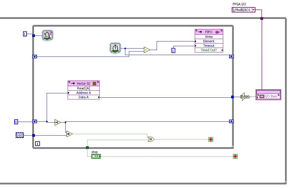
I read only analog output have about 38 tics. clock 40 MHz (RIO 9641)
My RIO gives me tics 107 = 112 - 5 analog outputs for the 1 iteration. If DAC cycle... The entire cycle takes (112 * 160 * 25th-9) for DAC 107 * 160 * 25th-9 = 428e-3 s always takes DAC, and I need more quickly.
How to set up outputs analog faster or rebuild program?I need the fastest analog output, is it possible?
Thanks for the help!
Hi togoto,.
Please let me know if I'm struggling to understand what you're trying to do, but the fastest, the analog output of the 9641 can update is 120 ticks by update. Which is based on the specification of the material on page 44 of the User Guide and the restriction that you touch. Therefore, I don't think you'll be able to get it down to 40 ticks.
-
Integrate the outputs analog with analog inputs
I have a program that displays 2 analog output waves and a separate program that captures the analog data through several materials of NEITHER. I need to integrate the program outputs analog in my analog input program.
The program of analog output is fixed as "AO_Triggers_LowLevel.vi" and the analog input is fixed as "ExperimentDAQ.vi". When I try and integrate these programs I get 'error-200560 occurred at DAQmx waiting until the Done.vi' to my function to wait until it makes my task of analog input (background of the program). I think it is my mistake in the order that I'm wiring to the top of my son of error but I'm not sure. I watched several tutorials (Timing and synchronization features of DAQmx) but I'm totally stuck.
Any suggestions are greatly appreciated. Thank you!
Alberto M.
I think I've fixed this problem. I extended my flat sequence structure to include the lines of task and error of my task outputs analog and things seem to work. I'm still not sure about what caused my error and why it has solved the problem...
-
Anyone know how this graph is created?
Hey, I found this, and I wondered if it's an effect... Anyone know how this graph is created?
Thanks in advance

Hello
Some ideas (illustrator, photoshop):
Writer III
http://www.AlphaPlugins.com/products/products.php?menu=get_prod_id&prod_id=2
Free effect action Illustration engraved for Photoshop
oshop http://blog.spoongraphics.co.uk/Freebies/Free-Engraved-illustration-Effect-Action-for-phot
https://www.YouTube.com/watch?v=-tNKVwJmjY0
https://Dribbble.com/shots/1878287-engraved-effect-Photoshop-action
Stone
-
I have FaceTime disabled through restrictions on my daughter's phone. However, she is still able to make and receive calls FaceTime. If it is limited, how this phenomenon is happening and is there a way to prevent it from happening in the future?
How do you know that she can always use Facetime?
Could she learned/guessed the password restriction?
-
I want to create an addon of firefox using python. Please let me know how this can be achieved
Hi team, support
I intend to create an Add on Firefox using python. Please let me know how this can be achieved.
Kind regards
Sandeep
Hi Sandeep, support.mozilla.org is for user only support, so we cannot give you advice for the development of extensions in this place.
Please see resources at https://developer.mozilla.org/en-US/Add-ons or check out the mozilla forum dedicated to the development of addon at https://forums.mozilla.org/viewforum.php?f=7.
Thank you
-
Suddenly, I can longer open my pictures folder. I tried to move a picture to the folder to see what is happening and received an error message saying I was not allowed to display the contents of the folder and if I move the picture here, I won't be able to see. I ran disk utility and found no permissions error.
How this could have happened and how can I fix this problem? I'm the only user. No one else has ever physical access to my computer. However, I sign up for Skyhub a few weeks ago and copied the contents of my Macbook it. Since then, a "Remote disk" icon on my hard drive. This would be part of the problem?
Select it, choose get the information on the file menu, open the section sharing and permissions and give you access.
(141083)
-
My iPhone 6 s Plus the function to rotate the screen how this return
My iPhone only more 6 used to rotate the screen, it is more the fact how this function returns
Swipe up from the bottom of the screen to bring up the control center. Then press the icon that looks like a padlock inside a circular arrow. https://support.Apple.com/en-us/HT204547
-AJ

Maybe you are looking for
-
Picture-in-picture (pip) works on macbook air 2013
Can't seem to locate in the specifications or support if my 2013 macbook air supports picture-in-picture function. I can't seem to make it work, but I don't know if it's the videos that I'm looking at the software, o
-
Using the 4th with Apple TV bluetooth keyboard
I want to know if Apple TV 4th will have no support for bluetooth keyboards? Thank you Ivan
-
I can't access wifi, please give me the name of the exact model of driver wifi
-
I've recently updated to 10 windows and Skype can't show my webcam video more (he did in windows 8.1). The microphone of my webcam works. When I go into settings, video settings, the webcam is loading continuously and also I get a pop-up that my amd
-
Can not see the photo of icloud on iMac
Goodday! For a while, I have a problem when you try to view the picture on my iMac that were made with my iPhone or iPad. Photo of what I do with my iPhone stream nicely to icloud and I can almost immediately see on my other devices (iPad etc.). Only