Generating analog output signals 4 with different frequencies
Hi all
I was trying to say to generate 4 different signals at different frequencies
1. first waveform is a sine wave with 5000 Hz,
2. other with 8000Hz,
3. third, one is a square with 25 Hz waveform and
4. fourth one with triangular waveform 50 Hz
all waveforms must be generated simultanoeusly.
I tried to generate with the task unique analog output and sample clock (clock rate is 100000). Cross in scope that I see only 5000 and 8000 Hz we generated correctly and the rest two waveforms show the incorrect frequency.
I guess that's due to the frequency of high clock to sample for more low frequencies for ex 25 Hz and 50 Hz. If I reduce the clock rate to get the lower frequencies properly so I can't generate frequencies higher correctly. (there's a clsh between frequencies and the clock frequency)
Is it possible to use DAQ board master sample clock and its magnitude downward revision (everywhere where it is necessary for each waveform separately) to generate all the signals at different frequencies at the same time in a single task?
Tags: NI Hardware
Similar Questions
-
Generate 2 Trains of pulses with different frequencies and Heavy duty with a PCI-MIO-16XE-10
Hello
I use a Board PEAK-MIO-16XE-10 DAQmx with LabView 8.6 to run a door for a piece of equipment controller. I need to create 2 separate, all pulse trains both trigger simultaneously, each with their own cycle frequency and duty. So far, I can create 1 pulse train and it works exactly as I need, however, whenever I try to enable the second train (called a door in this VI), I get an error saying: "the specified resourse is resevered," even though the first door is configured to use counter 1 and the second must be set to use counter 0. As I understand it, this map contains 2 separate counter/timer modules, so this should be possible. A large part of the rest seen in the attached VI's preparation for the signal processing and other controls that I use that I finished this VI.
Thank you
<><>
Hi Eric - you forgot to attach your VI. I did what you're trying to do with a similar card, but who has been using NOR-traditional DAQ (before DAQmx). It should be possible with DAQmx as well. A quick search on the forums turns up these two links, which suggests that your problem is that you try to create two tasks separate DAQmx, one for each counter. What you need to do is create a single task DAQmx which includes the two counters, then together, that their frequency and duty cycle regardless.
http://forums.NI.com/NI/board/message?board.ID=170&message.ID=241602
-
I use the outgoing/incoming analog DDK with the DAQ 6341 SMU map.
The examples, for example aoex5, show a single timer (method outTimerHelper::loadUI), but the example shows the DMA loaded with same size of vector data.
There is a comment in the outTimerHelper:
 call rogramUpdateCount, which implies that memory sizes different pad per channel can be used.
(the comment is: switching between the sizes of the various buffers is not used)
Nobody knows what should be the format the DMA buffer for data from multiple channels with different frequencies?
For example, we want a0 with a sinusoid at 1 kHz and a1 with a sine wave of 1.5 Khz. What looks like the DMA buffer?
With the same frequency for each channel, the data are interleaved, for example (ao0 #0, ao1 #0; ao0 ao1 #1, #1,...), but when the frequencies for each channel is different, what the stamp looks like?
Hello Kenstern,
Data are always intertwined since each card has only a single timing for each subsystem engine.
To AO, you must specify the number of samples that will be released to the AO. You also specify the number of channels. Because he didn't is that a single engine timing for AO, each AO will be channel will be updated at the same time to update clock tick. Data will be interlaced exactly as shown in the example because each channel AO needs output at each tick of the clock to update. The data itself can change depending on the frequency you want to copy.
kenstern wrote:
For example, we want a0 with a sinusoid at 1 kHz and a1 with a sine wave of 1.5 Khz. What looks like the DMA buffer?
With the same frequency for each channel, the data are interleaved, for example (ao0 #0, ao1 #0; ao0 ao1 #1, #1,...), but when the frequencies for each channel is different, what the stamp looks like?
In your example, you must come with an update rate that works for the two waveforms (sine waves of 1 and 1.5 KHz). To get a good representation of a sine wave, you need to update more than 10 x faster than your fastest frequency... I would recommend x 100 if possible.
Update frequency: 150 KHz
Channels: 2
Then create you stamps that include complete cycles of each wave you want to produce based on the frequency of update. These buffers must also be of the same size.
Buffer 1: Contains data for the sine wave of 1 KHz, 300 points 2 cycles of sine wave
Buffer 2: Contains data for the sine wave of 1.5 KHz, 300 points, 3 cycles of sine wave
You can Interleave them as before. When the data are performed through the ADC, they are out different sine waves, even if the AO channels are updated at the same speed.
-
How to determine the number of highlight ' to write ' for DAQmx generate analog output?
On the configuration of the stage for DAQmx generate analog output, there is a field "value to write. I can't find any explanation for what it is, how it determines the value to enter, nor what he writes. I am trying to go through the tutorials and it cling.
Someone would give an explanation?
Hello
To write value specifies the value to write in the channels, lines or ports selected in string parameters. In other words, this value will be the value of your DC output (for example if you enter 5, your output will be 5V). To get information on different fields in SignalExpress, access help"context-sensitive help. A pane will appear in your work environment that displays the coordinates of the field when you place your pointer over them.
For new users of SignalExpress:
Generation of DC signals with NI DAQmx devices: step in the DAQmx build, select 1 sample (on request) in the generation Mode dropdown. You can select a programmatic input to generate, or you can remove the check mark from the check box use programmatic input and specify a value for generating in the field of value to write . NOR-DAQmx help also provides additional information about the data generation.
Best regards
M Ali
Technical sales engineer
National Instruments
-
Several channels with different frequencies
Hello
I use card NI USB-6221.
The C API using, I need to generate 6 digital output channels, with frequencies of diffrenet and Heavy duty.
To be more precise, the 2 are totally identical, but I need them to be reversed, and the other 4 are similar to another, but should be shifted in time (I.e. There is a delay between each of the channels).
I used the 2 channels of CO that the USB-6221 takes charge for the first two signals, and it works very well (the two signals are synchronized and are reversed).
Now I need an additional 4 channels for the other vague square.
I saw an articale NOR by JohnP web site with the title:
Generate multiple channels of digital output with different frequencies and Heavy Duty
The following example shows how to create and generate a digital with the non-regeneration wave form so that you can change the frequency and the duty cycle on the fly with the M Series DAQ hardware X. The example uses output digital rather than counters to achieve this, so if you need more output than the available counters, it would be a good option (Note: on the materials of the M series an external sample clock must be provided, this may be caused by one of the counters if you want).
that seems to be exactly what I need, but the examples are for LabView which I did not.
Can someone explain how to do this with the C functions?
Best regards
Danny.
Hey Danny,
The important thing to note is that you can clock of arbitrary digital waveform (up to 1 MHz on the 6221). The real data acquisition programming is pretty easy once you have the waveform. My Example LV used LabVIEW Base generating function VIand then converted to a digital waveform to generate the signal from each channel.
The functions of LV helped tremendously with to achieve the waveforms to be updated on the fly (the basic function generator keeps track of phase for you).
If you do not need to be updated on the fly, then the construction of the waveform in C should not be too bad. For example:
P0.0 [1 1 1 1 1 1 1 1 1 1 0 0 0 0 0 0 0 0 0 0] * 1
P0.1 [0 0 0 0 0 0 1 1 1 1 1 1 1 1 1 1 0 0 0 0] * 2
P0.2 [0 0 0 0 0 0 0 0 0 0 1 1 1 1 1 1 1 1 1 1] * 4
P0.3 [1 1 1 1 1 0 0 0 0 0 0 0 0 0 0 1 1 1 1 1] * 8
[9 9 9 9 9 3 3 3 3 3 6 6 6 6 6 12 12 12 12 12]
The table above U8 would give you 4 output waveform of 50% duty cycle at Fs/20, shifted 90 degrees to eachother. The lines would be p0.0 by p0.3 (the bit rate of the U8 corresponds to what line goes high).
Best regards
-
Generate analog output with the software "Timing" on 6009
I see that the 6009 does not support the synchronization of the internal clock. We need to generate an analogue waveform which changes very slowly, it performs a cycle every 10-20 minutes.
I saw an old post on the use of calendar software, but can not find a way to do this using SignalExpress.
Any ideas or references to examples of messages, etc. are greatly appreciated.
Analog output clocked by the software (DAQmx) in SignalExpress
I hope this helps.
-
variable phase shift between two analog output signals
Hey! I would drive two different piezo elements with an sine - / square signals and have a phase shifted output signals. After some trail and error, I was able to get a second analog output on my card PCI-6221 (using LabView 8.2) also allowed me to have different amplitudes for both signals. However, I could not output signal having a frequency different and most importantly to my request to have one of the signals variably shifted phase.
Thanks for the very useful suggestion. I have attached the file .vi installation I've run so far.
Hello!
A way to generate waveforms is using the analog waveform Toolbox. I created an example VI that is attached and that shows you a way to use the base generating function VI. I saved for LabVIEW 8.2.
I hope this helps!
-
Generate analog output waveform finish on request
Hello.
I have a VI that reads in two data channels (400 samples at 400 Hz), calculates the characteristics and classifies data based on a model. If the class is a certain State, a Boolean value called "Détection" is set to True. A second Boolean value called "Stimulation" is also set to true and flip flops and turn off every second up to what the "detection" is more true. Now that I am reading and classify a second data, Boolean values may only be updated once per second. I am wanting to generate output "Stimulation" Boolean is true analog. I had been accomplish this by generating a sinusoidal signal all the time and write to a buffer in a separate loop (500 samples per writing @ 10 kHz) and multiplying by zeros if "Stimulation" was false. I have a code that more or less does what I want, but there is a delay of ~ 200ms between 'Stimulus' is set to True and AO generation, and I feel like it could be simplified. I was wondering if it would be better to generate a waveform finished and trigger to write with the Boolean value of 'Stimulus' (i.e. write 1 second of a sine wave to the changing state rather than write 20 sections of a sine wave in a second, while the Boolean value is True).
Y at - it a good way to do this with daqmx functions? (Generate a waveform of defined duration when a control changes)
-
C++ PCI-6703 generate analog output
Hello
I'm new on Measurement Studio for VC ++ and I need your help.
I have a PCI-6703 with a box-CBS 68.
I installed the drivers necessary for NOR-DAQmx measurement & motor with Solution Explorer.
I installed the software measurement Studio 2009 (trial pending the validation that my project leader buys the full version).
I work in Visual Studio 2008 and VC ++ (I can't use LabView (if it was not easier) to synchronize the codes for the entire project).I want to generate analog voltages (10V) at the exit of the PCI-6703 for SCB - 68 box. This will send signals to an eCard to turn lights.
I tried these lines of code, but it does not work (I am inspired by the codes I found on the forum):#include
#include "windows.h".
#includeint main (int argc, char * argv [])
{
TaskHandle daqmxhandle;If (InitCVIRTE (0, argv, 0) == 0)
Returns - 1; / * memory * /.DAQmxCreateTask ("", & daqmxhandle ");
DAQmxCreateAOVoltageChan (daqmxhandle, "Dev1/ao0", "",-10,0, 10.0,)
DAQmx_Val_Volts, "");
for (int i = 0; i)<>
{
DAQmxWriteAnalogScalarF64 (daqmxhandle, 0, 10, 10.0, 1);
Sleep (3000);
DAQmxWriteAnalogScalarF64 (daqmxhandle, 10.0, 1, 0, 0);
Sleep (3000);
}
DAQmxClearTask (daqmxhandle);
return 0;
}-----------------------------------------------Error----------------------------------------------------------
1 >-rebuild all started: project: test1, Configuration: Debug Win32 -.
1 > deleting intermediate files and output from 'test1' project, configuration ' Debug | Win32'
1 > compilation...
1 > test1.cpp
1 > c:\program files\microsoft sdks\windows\v6.0a\include\winnt.h(7256): warning C4005: 'THREAD_BASE_PRIORITY_MIN': macro redefinition
1 > c:\program NIUninstaller instruments\measurementstudiovs2008\vcnet\include\cvidef.h(140): see previous definition of 'THREAD_BASE_PRIORITY_MIN '.
1 > c:\program files\microsoft sdks\windows\v6.0a\include\winnt.h(7257): warning C4005: 'THREAD_BASE_PRIORITY_IDLE': macro redefinition
1 > c:\program NIUninstaller instruments\measurementstudiovs2008\vcnet\include\cvidef.h(143): see previous definition of 'THREAD_BASE_PRIORITY_IDLE '.
1 > manifest compilation of resources...
1 > version of the compiler Microsoft (R) Windows (R) Resource 6.1.6723.1
1 > copyright (C) Microsoft Corporation. All rights reserved.
1 > Linking...
1 > test1.obj: error LNK2019: symbol _DAQmxClearTask@4 referenced in function _main outstanding external
1 > test1.obj: error LNK2019: symbol _DAQmxWriteAnalogScalarF64@28 referenced in function _main outstanding external
1 > test1.obj: error LNK2019: symbol _DAQmxCreateAOVoltageChan@36 referenced in function _main outstanding external
1 > test1.obj: error LNK2019: symbol _DAQmxCreateTask@8 referenced in function _main outstanding external
1 > test1.obj: error LNK2019: symbol _InitCVIRTEEx@12 referenced in function _main outstanding external
1 > C:\Documents and Settings\Default\Mes documents\Visual Studio 2008\Projects\test1\Debug\test1.exe: fatal error LNK1120: 5 unresolved external
1 > build log was recorded at the 'file://c:\Documents and Settings\Default\Mes documents\Visual Studio 2008\Projects\test1\test1\Debug\BuildLog.htm ".
1 > test1 - 6 error (s), 2 warning (s)
= Rebuild everything: 0 succeeded, 1 failure, 0 was ignored.Hi AndriRavo,
I have seen that you had the cvirte library.
You can't use it with Visual Studio. This library and functions such as InitCVIRTE are used when you program with CVI.
Just use DAQmx features but remove all features CVI for example you found.
#include "windows.h".
#includeint main (int argc, char * argv [])
{
TaskHandle daqmxhandle;DAQmxCreateTask ("", & daqmxhandle ");
DAQmxCreateAOVoltageChan (daqmxhandle, "Dev1/ao0", "",-10,0, 10.0,)
DAQmx_Val_Volts, "");
for (int i = 0; i)<>
{
DAQmxWriteAnalogScalarF64 (daqmxhandle, 0, 10, 10.0, 1);
Sleep (3000);
DAQmxWriteAnalogScalarF64 (daqmxhandle, 10.0, 1, 0, 0);
Sleep (3000);
}
DAQmxClearTask (daqmxhandle);
return 0;
}Kind regards
-
Develop the analog output signal
Let me start by saying that I am a new user of LabVIEW. My experience with LabVIEW is limited to a briefing in which we covered documents in the guide, «Introduction to LabVIEW and Computer-Based measurements» manual the customer Hands-on With regard to what I'm trying to accomplish:
I'm using LabVIEW 8.6, OR cDAQ-9172 and number of NI 9205 and NI 9264 module. I have a load cell that requires a constant supply of 10V to operate. I don't know how to generate this signal or the signal in mV, which is removed from the load to the cDAQ-9172 cell. I tried using DAQ-Express for entry and exit signals. Once I have created two assistants DAQ, I'm not sure what to do next. In addition, the load cell has four sons: green, white, red and black. Green = + GIS, red = + EXC, white = - GIS and black = - Exc. The Red wire is connected to ao0 and the black wire is connected to the COM of NI 9264. the Green wire is connected to ai18 and the white wire is connected to the NI 9205 module ai26.
Any help on this is greatly appreciated!
Yatsco
Hello Yatsco,
Fan of the crows is correct that you would be more successful using a NI 9219 instead of the combination of the PCI module, HAVE / AO. However, it might be possible to use the modules, you should use the load cell, that you try to use, but we need more information on the sensor to say with certainty. A link to form would be preferable.
Assuming that everything would work out with the sensor itself, I would do something like the following:
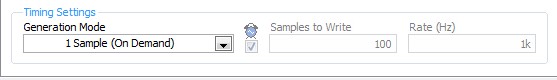
- Configure your analog output DAQ Assistant for output on the 9264 ao0, leave all default settings except for the generation Mode, you should change it to 1 sample (on request).
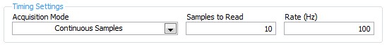
- Configure your analog input DAQ Assistant enter ai18, keep all the default settings again except for sync settings, which should resemble the following:
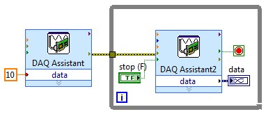
- Your drawing should look like this:
If you do this and you encounter problems with your sensor or its response after the datasheet (or at least the manufacturer and part number), and I'll look into it further.
- Configure your analog output DAQ Assistant for output on the 9264 ao0, leave all default settings except for the generation Mode, you should change it to 1 sample (on request).
-
Change the sequence of commands to generate two reports by USE with different names.
I have a special situation for the model of batch processing.
Each DUT consist of two distinct products that need to be tested as a single unit.
I can run every USE and generate a test for each report. -aka. The standard use case works very well.
However, we would like the records using this method. So I need a copy with a different name for each series.
The idea behind this is that we have a story running for each half of the UUT. Given that the two halves will probably never meet.
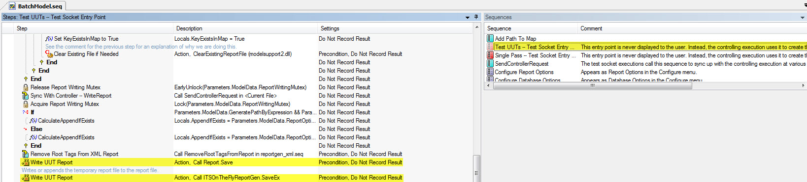
I looked at the BatchModel.seq and read some of the documentation, but I'm having a hard time to understand what is happening.
I guess the items highlighted above are where the object to measure reports are generated. However, I don't know the mechanism for giving them the names among the Options report-> report menu Pathname file or how to change between these two points in time. Also are there tricks to get the report in duplicate with a different path in this configuration.
All links to the relevant information would be useful. Thank you
Just copy these two steps and between them and the copies have another step that is just a statement. There, you can change the path of the report by setting parameters. TestSocket.ReportFilePath the new path.
Ideally what you would do, is that the client using a callback. So, your code would look like this:
Write the object to measure report
Write the report of the object to be measured (on the fly)
Define report path reminder (override in customer OR statement step)
Write the object to measure report
Write the report of the object to be measured (on the fly)
Hope this helps,
-
Greetings,
I use a DAQ Assistant to output a 0 - 5V signal. I added a Triangle pattern at the entrance of the DAQ Assistant.
The point is that I do 0 - 5V and then back to 0V. But the problem is that the DAQ Assistant stops just to 1V.
P.s. I have the DAQ Assistant, in a loop ForThanks in advance
-
PCI, I / AO at a different frequency
Hello
As a newbie, I met a problem when I tried at the entrance and the analog output signal at a different frequency.
I followed PID-control - Multichannel .vi to build a control program, so input/output can be synchronized. However, the project requires that the frequency of I be tenfold of the AO. I could re-write the while loop to make the output value constant for 9 of 10 cycles. However, in my view, it is simplest way to do.
Anyone provide an example?
Thank you in advance.
Sincerely yours
Ming
lmuri wrote:
Hello
As a newbie, I met a problem when I tried at the entrance and the analog output signal at a different frequency.
I followed PID-control - Multichannel .vi to build a control program, so input/output can be synchronized. However, the project requires that the frequency of I be tenfold of the AO. I could re-write the while loop to make the output value constant for 9 of 10 cycles. However, in my view, it is simplest way to do.
Anyone provide an example?
Thank you in advance.
Sincerely yours
Ming
Hello Ming!
Please use the Forums of NOR. You'll be happy to know DAQmx allows what I/O tasks such as these to be not run not only at the same time, but at different rates.
The problem with the solution that you have imagined is that this implementation will remove the delegation of tasks to the hardware level, and your program would become software-driven; This becomes a problem when you perform tasks of acquiring data at very high speeds as it becomes limited to the speed of your operating system (OS).
You can coordinate your tasks to operate synchronously and perform the output and the acquisition at different rates by creating a maintask. This means generally that you configure a task by DAQmx that keeps a clock frequency and you create tasks that use this clock frequency, or a division thereof, to exploit to their own individual frequency. This facilitated not only the execution of DAQmx tasks synchronous but also provide a material entirely focused on the solution of performance maximimse.
Thanks to LabVIEW, if you go to help > examples find to open the Finder of example of OR. If you are browsing material input and output > DAQmx > synchronization > multifunction > Multi - multifunction - Synch Dig read write with Counter.vi, you will find an example of how to set up a counter as a master of the task to control the operation of operation both a reading and writing . (This example shows a digital but implementation may be easily replaced by analog).
By setting the meter to the maximum frequency rate that you will require for your task (in this case, the speed at which you want to copy values) and apply it to the output of the SampleClocktask, you will drive the clock output task with the counter as the clock source. You can then use the meter as the source of the SampleClock for the task of entry, however to set the rate at any division of the driving frequency. In the case of your example, you can set the bit rate to 0.1 times the frequency counter to acquire a 10th of the rate.
If you want to acquire at the same rate, but only to retrieve values on the 10th of the speed, this same solution can be configured to produce instead a trigger to return an acquisition in the buffer. With a master synchronizing the task, the possibilities are endless!
I hope you find it useful, and if you need a precision more do not hesitate to let me know. Have fun with your DAQ!
-
Hello guys,.
I have a general question regarding the units of packaging such as the USB-9263 analog output signal. If I can use it instead of data acquisition to provide an analog voltage output?
Thank you
ELA
Yes, the 9263 can provide 4 output channels analog voltage (+/-10 v range) with up to 1mA of current drive. Looks like: it refers to the short circuit of conditioning of signals and some protection against overvoltage. Link below is the User Guide:
http://www.NI.com/PDF/manuals/372406b.PDF
-AK2DM
-
output signals of the rectangle a PEAK sine wave conversion
Hello
I have a question on the treatment of a PIC16F84 output signals. It seems that the simulation of Multisim does not work properly - but before I blame Multisim, I ask the community NOR or software engineers or a solution. Because I'm German, you are invited to continue this thread in German if it is allowed by the rules of the forum. If you need additional information to analyze my problem, I'll be happy to provide.
The circuit itself has to convert "composition by pulse" signals "tone" (DTMF tones). So you can get old, classic phones work on new devices that do not support the "composition of pulse" more.
The circuit is powered by the analog telephone line current loop line. The PIC is provided by a rudimentary voltage regulation and count pulse signals (voltage failures / power interruption on the telephone line). After that the captain means the series of impulses in their equal number (e.g. 3 pulses = number 3). The captain gives finally two signals with different frequencies to generate a DTMF tone (e.g. number 3 here is 697 and 1477Hz). As you can see in my PDF file attached, it works very well.
Now I have to convert the rectangle wave given by the captain to an at least similar to a sine wave form - otherwise the device that receives the DTMF tones won't understand them.
So I connected a low-pass filter at the output of the PIC. Now, expect the rectangle signal to be smooth in a way as the 'e-function' will (loading / discharging a capacitor through a resistor). But the results are very far from that - as you can see I have very strange curves.
When I implemented a frequency generator with the same output signal as the PEAK and the low pass filter even I get curves as expected.
So we can say that the output of the PIC works like a frequency generator in my circuit. But why does the filter not behave as it should?
I've tried a lot of different values for the parameters of my RC-filter and simulation - this does not solve the problem.
It would be nice if someone has any idea how to solve this problem.
Thank you.
The output impedance of the PEAK may be too high. May be that my car 50 output? Try scaling of impedance of the filter. Do the 10000 ohms resistance and capacitor 10 nF.
Lynn
Maybe you are looking for
-
How can I change my payment with a Visa card, I no longer use my gift card account. I don't have the gift card so I don't know the PIN code. I have the amount of the card on account, what should I do?
-
I can't change my security questions
I can't change my security questions
-
Unable to connect more than 2 products to TM
For some time now, I have problems with wifi at home. It seems that only two or three devices can be connected at any given time. If my MBP and Iphone is connected to my wifis MBA is thrown and invited to restart the device (router) if the router is
-
The button on the control panel flashes 4 times then stays on for 3 seconds, after that the other LEDs will be lit for about 2 seconds. Then rehearsals and I can get there, any advice would be great thanks!
-
XP Home Edition Backup without the XP CD
I want to backup my computer Dell with XP Home Edition, but did not have the XP CD because the operating system has been installed when I bought the computer. Windows instructions indicate that you need the CD to download the backup program. Backup