Part of a Signal amplitude
Hello!
I managed to find the amplitude of the signal saved as a spreadsheet using Amplitude and Levels.vi together. It works very well. How can I find the part of the signal amplitude (let's say the first 10% or 0.0001 seconds)? In a Word, how do I set up time limits for VI?
Thanks for your help.
Judging by your code you seem to have a good understanding of the manipulation of waveform. You can use the get Wfm subset VI (waveform palette) or just to roll your own hoarder of subset in the tools of the table palette. The subset of Wfm get has the advantage of calculating the time based on the dt.
Tags: NI Software
Similar Questions
-
Low signal Amplitude on PXI-4461
I currently use two PXI to generate an analog signal through LabVIEW 2009 to an oscilloscope:

PXI-4461 runs below the attachment (properly labeled). It also produces the green line on the graph. It seems OK on the oscilloscope.
PXI-5412 runs the other (properly labeled) attachment below. It produces the yellow line on the graph. This amplitude is measured properly (or so it shows in the margin of the image), however it gives me a warning of "Low Amplitude of the Signal" and displays the wave that is much smaller than the "correct" version of the 4461.
* Note: I guess it's possible that the PXI-4461 (green) is false and the PXI-5412 (yellow) is right, but as the PXI-5412 (yellow) produces the error, I am led to believe that this is the problem.
I could use help to find out what could be causing this inconsistency and how I could do to fix this problem.
This has nothing to do with LabVIEW. This is the oscilloscope all partners. The reason why the yellow signal is smaller than green is because your ranges are different. Look at the bottom of your oscilloscpe: Ch2 said "500mV by division" while channel 3 said "1V by division. You probably get a "low signal amplitude" because you report is less than '2 divisions' and offer thus the scope allows you to change this. There is a button named "Autoscale" your bezel that you can hit if you want.
-
How can I extract a part of a signal inside a loop control and simulation?
I would like to extract the part of my signal between 0 and 3 seconds. I tried to use the extract of Portion of Signal VI Express, but it does not work. I'm setting the length to the offset 0 and 3 seconds. However, nothing is displayed in the output. I used this before VI successfully, but it wasn't in a loop control and simulation. Is there something special I need to do to make this work properly in this case?
This forum shows how to measure the time between the Digital pulse http://forums.ni.com/t5/LabVIEW/Measuring-time-between-digital-pulses/td-p/1056881
In addition, it would be a good link https://decibel.ni.com/content/docs/DOC-12160
-
Determine the position of a part of the signal on a graph
Hi all
I have a problem. I determine the position of a part of the signal on a chart. So, I have to determine the maximum value of the part (this is not a problem).
Signal a lot of noise. I did some filtration but still signal have noise. Concerning this, filter change signal, two later when I take one measure, there is a possibility that this is not true.
Anyone has idea how to determine the position of a part of a signal automatically, for the various signals (similar).
There are photos attached where is what belongs to an interest in a signal. There is a VI where is an a test signal.
Thank you
Hello
From the screenshot, I understand that you only interested in the local maximum of the signal.
There is a VI that detects peaks when you specify a certaing point and this point maximum width.
Later, it's just a matter of setting the value of local maximum of you. Basically, you'll have to point once again got 1 d table than VI.
I enclose a VI that can be a good starting point for your application.
Best regards
Ion R.
-
extract the random part of the signal
If I'm loading a signal from a LVM file, is there a way to extract a random part of the signal? Just some information, I load several files through a loop/case structure and each of the files can be of different lengths, so I don't know beforehand how long the signal is.
Thank you
George
The best way to do what you want to do is the following:
- Read the file using the Express read the file of measures. It will show the entire file in memory.
- This convert a unique waveform or table of waveforms using the Express Of the DDT. This will not create a copy of data.
- Point of use of Detection of level trigger base to find the location of your departure.
- Get the subset of waveform to pick the section of interest.
If your waveforms are large enough so that it causes memory problems, you can analyze the text of the file directly, but it is much more complicated and could easily be much slower if you do not quite accurate (see notes above). If you need to pursue this matter, let know us and we can provide the best direction.
-
FPGA acquires only the positive part of the signal
Hi all
I have the NI USB-7855R and using the personality of DAQ balanced example of e/s (http://www.ni.com/example/5961/en/). I plugged my generator Agilent to AI0 (in mode CSR) and I have the following problems:
(1) waveform graph in LabVIEW is only to show the positive part of the sine wave that I am providing to the Board of Directors (clipping at 0 V). Only by compensating the signal from the signal generator, I am able to get the two cycles.
(2) while I am out 5 Vpp on the generator of signals on the graph of a waveform in LabVIEW I see only 1.5 mVp.
Any suggestions on what could be the problem?
Thanks in advance or your help!
The first graph of "analog input" in your link shows the analog inputs are converted to unsigned integers (U32) before their passage in the FPGA-> host FIFO. Negative values will obviously be lost make this conversion.
-
Export part of the signal in ASCII or excel
It is possible to select a part of the data stored and export it and not the whole record?
Munir
Hey Munir.
In addition to suggestions of Maria, you can also do the following:
1. in the window log (which is by default at the bottom left of the main application window), expand the symbol '+' next to the log that you want to export.
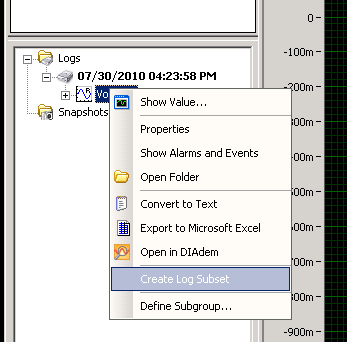
2. right click on the high level group of data and select 'create journal subset"(as shown below). This will open a dialog box that allows you to create a subset of time your selected data. Either use the Start Time/Stop Time indicators to make your selection of subset or use red cursors on the preview graph. Then click on create.
3. when the dialog box disappears, you will have a new entry of newspaper with the same name and the word "subset". Expand this new subset of newspaper and right click on the high level group. You will have 3 export options: a) convert text, b) export to Microsoft Excel and c) open in tiara. Select the option you want.
Hope this helps also.
Phil
-
Amplitude measurement of a continuous signal in a given time window
I'm working on an acquisition system that acquires a continuous signal of 250 kHz. My goal is to measure the amplitude peak-peak of the first reaction of signal, the problem with my setup, this is the first part of the signal is always higher than the part of the signal that I'm interested. If I try to use the measure of max from Ridge to ridge of signal VI then responds with the measure of Ridge Crest of the initial part of the signal. See the attachment for a better understanding, I would still like to view the raw signal as is, but I would like to measure the peak voltage at peak of the signal between the yellow sliders.
Thanks in advance...
If transient initial always occurs in the first 12 microseconds, you can use any subset of table or similar wave function to retrieve the last part of the wave. Then use the measurement from Ridge to Ridge on this subset.
Lynn
-
How do I create a traction voltage as a control signal upward?
I use a minimum/maximum statistics module, but is unable to route the analog data to all 16 entries that I need this module (I suppose a limitation of current car, but I don't know why this would be necessary in the software). My first thought was to use a Signal Amplitude controlled router to expand this case 15th signal at 16. It seems that, since I want the router to Signal to be always active (ON) that I don't want to pull up to command input the Signal from the router. How to create a pull upward which is common in digital electronics for this?
It is not a limitation of current car, but simply that you can plug a wire 15 times, for up to 16 destinations. You can work around this by inserting a module of scaling, the NOP value, then its output for up to 16 more destinations.
-
How to get analog tacho signal in card PCI-6250 OR
Dear all,
IAM using Labview 8.6.1 and map NI PCI-6250. In my application, I need to get the power spectrum of the order for a given speed and signal of the accelerometer. So iam using labview example program command power spectrum(Analog_Tacho).VI. In my PCI6250 card, I have configured AI0 as the accelerometer signal and AI 1 as speed for tacho signal analog signal. In this sample program I can get the signal Amplitude of had it, but I can't able to get the speed profile. For iam speed using the encoder, encode this pulse digital I connected to the analog channel 1. If this connection is correct? Instead of giving digital impulses directly I tried the analog signal 0 - 10v for 0-based-1500 rpm. This configuration also does not work. Encoder PPR is 1000. Can someone help me solve my problem.
Kind regards
Vijay.
At 1800 rpm spin you at 30 Hz. for your encoder impulses come to 30 000 Hz. You must try the channel analog encoder to 100,000 samples per second or more. The chart of your analog inputs on a graph of time waveform to see if you get a clean signal.
With tacho analog vi, you will need to provide the number of pulses per turn, so it can determine the correct speed.
-
Signal noisy and shielding techniques
Hi all
I'm having a problem with excessive noise on one of the signals in my test system.
The signal source is a third party device (interface to a sensor box) which produces a 0 - 1.0V signal proportional to the signal output. The signal is connected to a box distribution, then on my NI DAQ device via a Terminal SCB68. I use differential inputs.
As far as I know all the armor is correct. I know that it would be ideal to attach the chassis ground to the mass of the signal at the source, but it is not possible. The chassis of the signal source is not based, so there should not be a current loop in armor.
For a typical signal, I get about 20 mv (peak-to-peak) of higher frequency (> 100 Hz) noise and > 200 mV lower frequency noise ~ 20 Hz.
I have not been able to isolate the source of noise or to reduce the noise all additional levels. The lower frequency noise consists mainly of not sinusoidal noise peaks.
A wiring diagram is attached. I have the shield related to a 10 megaohm resistor that is connected to the Terminal GND of AI. I know it is different than what is recommended in the documentation, but I read other resources recommended in this regard. If I remove the resistance, noise doubles.
Thanks for your time.

1 if the signal is soemwhere Earth, then you don't have a differential signal. Although any difference in potential between the soil in the area of distribution of the signal and the SCB68 may appear as if it is part of the signal connected to the - entry. Do not put earth it or not use the setting differential input.
2 see 1.
3 OK. One end of the floating shield often helps.
I fear that ground in the distribution of signal box can be part of the problem. What was the reason for making this connection? Why here rather than at one end or the other or no ground at all?
What is the source of signal? What kind of sensor? How many channels will you measure?
Lynn
-
Problem with the biphasic signal generator
Hello!
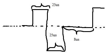
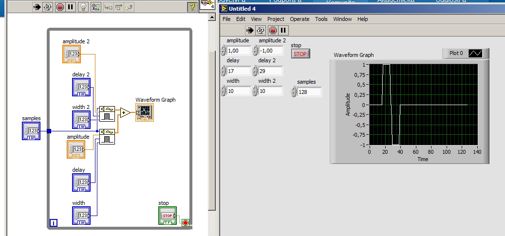
I filtered signal and detected envelope with OATS envelope detection.vi of given length. And now I need to modulate signal biphasic (photo). The biphasic signal should be the same length as my envelope signal. I want to be able to change the width of peak (25us) time and period, frequency (1 kHz), the biphasic signal amplitude (1). I know that I can start with pulse pattern.vi (check my diagram). But I don't know how to put together it me give only a single period. I have LabVIEW 2013.
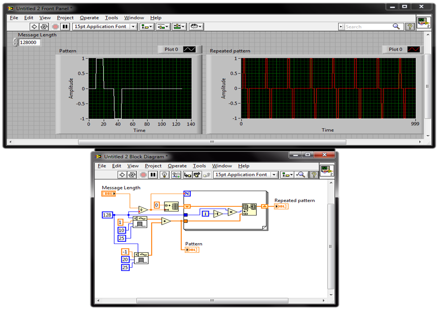
You can repeat your profile of signals using a loop. Keep in the Middle the number of times where the model is repeted depends on the length of the theme of your message and the sampling frequency, you use the model and the message. Check this picture (just a quick suggestion):
best,
-
Bill land - problem with phase
I have a problem of implementation during the attempt to produce traces of Bode for my team designed the hardware. I have now successfully been able to produce the data you expect, with a single question. Part of the phase of data points are the opposite of what is expected. I'll explain the process used...
The material, I log in allows me to inject the signals on channels, but also the flow of these channels of my PC application for analysis. The function that I'm trying to replicate is a frequency sweep, as follows:
-major equipment to replace a channel (the stimulus) with an sine wave frequencies, f
-broadcasting the channel stimulus as well as his response to a certain channel number of cycles, P
-the analysis ("transfer function") on the stimulus and data stream response strings
-connect the frequency (f) with the phase intended to produce a Plot of Bode and corresponding calculated magnitude
-increase the frequency (f) and repeat steps
This code example is 'analysis' performed:
int i, MaxMagIdx, DontCareIdx;
Double * TimeInMag,.
* DontCareArr,
TransferReal,
TransferImg,
TransferMag,
TransferPhase,
DontCare,
AdjFreq;NIComplexNumber * TimeSweepIn,.
* TimeSweepOut,
* FFTSweepIn,
* FFTSweepOut;TimeSweepIn = malloc (gSweepCountMax * sizeof (NIComplexNumber));
TimeSweepOut = malloc (gSweepCountMax * sizeof (NIComplexNumber));
FFTSweepIn = malloc (gSweepCountMax * sizeof (NIComplexNumber));
FFTSweepOut = malloc (gSweepCountMax * sizeof (NIComplexNumber));TimeInMag = malloc (gSweepCountMax * sizeof (double));
DontCareArr = malloc (gSweepCountMax * sizeof (double));int InputSigIndex;
unsigned char OverrideMsg [L_ADC_OVERRIDE_RQ] is {0};.
for (i = 0; i<>
{
TimeSweepIn [i] .reellement = gSweepInArr [i];
TimeSweepOut [i] .reellement = gSweepOutArr [i];
TimeSweepIn [i] .imaginary = 0.0;
TimeSweepOut [i] .imaginary = 0.0;
}CxFFTEx (TimeSweepIn, gSweepCountMax, gSweepCountMax, NULL, FALSE, FFTSweepIn);
CxFFTEx (TimeSweepOut, gSweepCountMax, gSweepCountMax, NULL, FALSE, FFTSweepOut);for (i = 0; i<>
{
ToPolar (FFTSweepIn [i] .reellement, FFTSweepIn [i] .imaginary & TimeInMag [i], & DontCareArr [i]);
}MaxMin1D (TimeInMag, gSweepCountMax, & DontCare, & MaxMagIdx, & DontCare & DontCareIdx);
CxDiv (.reellement [MaxMagIdx] FFTSweepOut, FFTSweepOut [MaxMagIdx] .imaginary,
FFTSweepIn [MaxMagIdx] .reellement .imaginary FFTSweepIn [MaxMagIdx],
& TransferReal, & TransferImg);ToPolar (TransferReal, TransferImg, & TransferMag & TransferPhase);
TransferMag = 20 * log10 (TransferMag);
TransferPhase = RadToDeg (TransferPhase);AdjFreq = (double) ((unsigned long) (gSweepFreq * 0 x 200000000 / (double) 50000000)) * 0 200000000 50000000 x / (double);
fprintf (Logfile_Handle, "% lf\t%lf\t%lf\n", AdjFreq, TransferMag, TransferPhase);
Free (TimeSweepIn);
Free (TimeSweepOut);
Free (FFTSweepIn);
Free (FFTSweepOut);
Free (TimeInMag);
Free (DontCareArr);It works almost perfectly. The problem is that the calculated phase will be positive when there should be negative and vice versa.
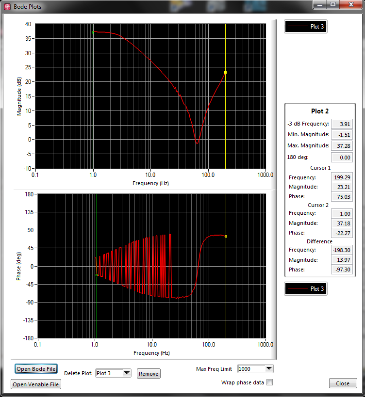
Here's a graph of the data produced:
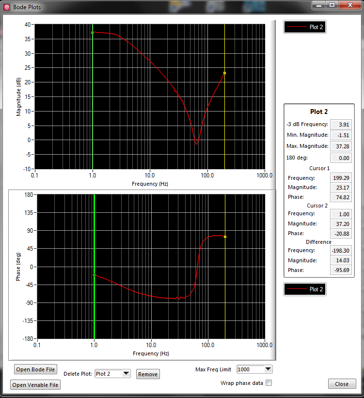
This is what is expected:
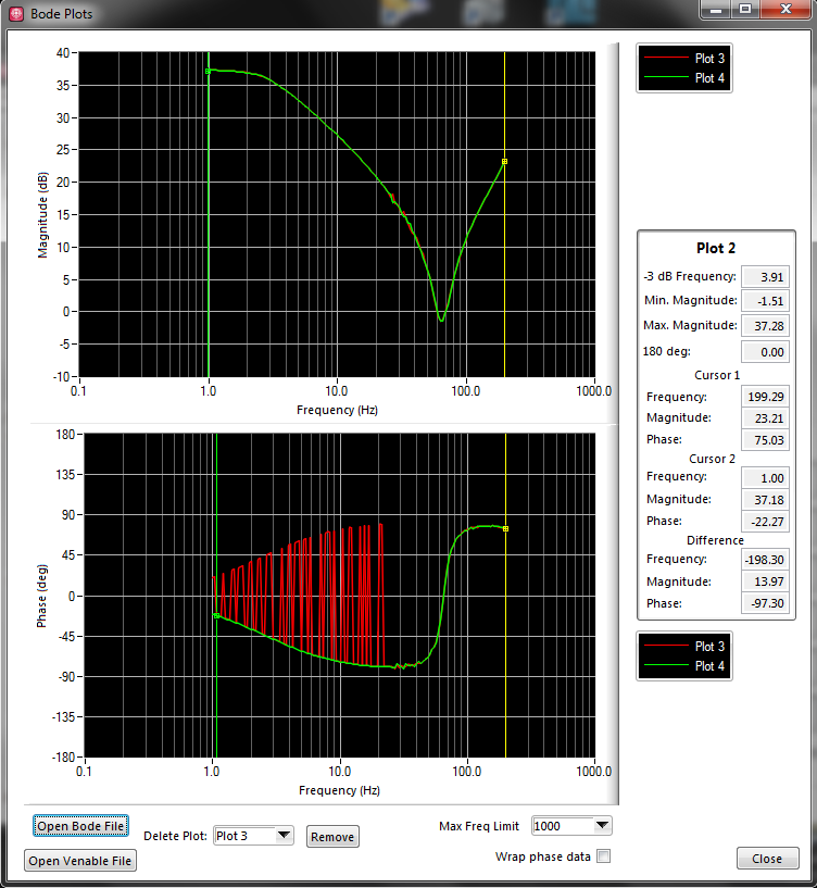
Here are the two bunk:
The expected plot was produced by the log file of cheating. I went and I didn't change the incorrect points to negative values. I want to eliminate this step. As you can see, if incorrect data are reflected on the zero line, it's what we expect. This "expected" given corresponds to what material Analyzer of my colleague (Venable device) when it is used on our device.
We believe that the issue is not with carried out complex math, but a problem in the FFT function or the selection of the index to use on the data table.
Hi PedroMunoz,
It was random semi.
With the help of a licensed physicist with a PhD, the solution was discovered.
When a FFT is performed, the output is a complex signal frequency. Convert this signal complex in amplitude and phase. The signal amplitude must contain a pic. The ridge of the signal amplitude is located at the frequency at which the sample represents. I understood.
However, reading the FFT also of output magntiude contains a second peak. This second peak is negative frequency, and to analyze these data point conjugate complex is necessary. This second Summit should theoretically have the same amplitude, described as:
F (f) = F * (-f)
What interests me in recovering is F (f). What was happening was because F (f) and F * (-f) are theoretically the same (hence, they should the two registry as the maximum value of the table), F * (-f) would sometimes be picked up as the maximum value of the table instead of F (f), perhaps because of the noise. So I just need to make sure that I'm not the negative frequencies in my table.
To ignore the F * (-f), all I had to do was only to watch a half of my output of the FFT. When I change my code for:
TimeInMag = malloc (gSweepCountMax/2 * sizeof (double));
DontCareArr = malloc (gSweepCountMax/2 * sizeof (double));for (i = 0; i
{
ToPolar (FFTSweepIn [i] .reellement, FFTSweepIn [i] .imaginary & TimeInMag [i], & DontCareArr [i]);
}
MaxMin1D (TimeInMag, gSweepCountMax/2, & DontCare, & MaxMagIdx, & DontCare, & DontCareIdx);I'm ignoring the negative frequencies. By setting the parameter 'shift' of CxFFTEx to FALSE, it organizes the positive frequencies in the first half, then the negative frequencies in the second. I pick up is no longer the wrong index, which would result in the phase reverse reading.
I hope this helps someone else in the future!
-
Hi all
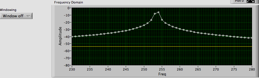
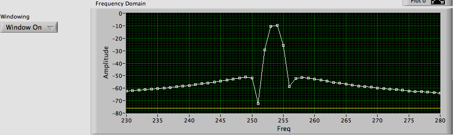
I'm trying to demonstrate the concept of the leak and the effect of the use of windowing. I implemented a simple VI which is attached using LabVIEW 2011.
My question is, why does the amplitude of the signal in the frequency domain decrease instead of increase to the maximum frequency when I apply a windowed function.
If I understand correctly, apply a window means that I overcame the leak problem and I should get a magnitude higher (than without the help of a window) to the frequency of peak. I'm wrong?, or this higher amplitudes will be only in the frequencies around the frequency of peak?
Another thing, why if the number of cycles is greater than 2.5, I begin to see the folding occur. If this is related to the aliasing, why did not see this beyond number of cycles 2 (Nyquist Theroem) not 2.5 folding.
I appreciate your help.
Part of the explanation for the reduced amplitude is simple while other parts may be more complicated.
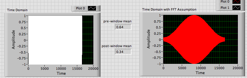
The easy part: after windowing there is less energy in the signal. The parties near beginning and end of the data segment have reduced the amplitude compared to the signal UN-windowed. Remember that the Fourier transformation is to integrate over infinite time. Essentially, this means that the energy in each slot of average frequency is calculated on the duration of the signal. The tip of both windows and non windows signals amplitudes are ~ 1 but the means are very different.
The most complicated part: the location (exact frequency) energy in a bin and the number of slots occupied by the signal affect the amplitude of the highlight. In the images below, about 50 points are above 40 dB with the window off the coast, only 4 are above 50 dB in the image window. If you make all the energy of the signal, it is here.
The folding you see is due to fractional cycles when you concatenate the berries. For any value of cycles that is not an integer multiple of 0.5, you will see strange waveforms at the exit of the box of the window structure. When you have an odd number of alternations, you get the appearance of a phase inversion. I really don't understand what you're trying to do with half top of your schema.
Lynn
-
Hello
I have a sinusoidal signal that oscillates around zero the axis in the negitave and positive. It is to measure the height of the waves on the static water level in a wave tank. I am calculating the FFT but the amplitude is less than the height of the waves in the time domain. Does this mean that I'm the wrong calculation? I don't know wheather I should use the FFT Peak or RMS? I assumed that the amplitude of the FFT should give me the same amplitude as the time domain.
Any advice would be greatly appreciated.
Thank you
Donners,
It can get complicated, but I suspect that what you see is the result of the frequency of the waves is not not exactly at the frequency of the FFT bins. For example, suppose that df = 1 Hz. Then each element of the array FFT represents the energy in a "sandbox" a hertz wide centred on the frequencies of the integer. For a wave with most of his energy to 7.3 Hz TFF likely values not null for trays Hz 7 and 8. In real systems with noise and light frequency variations, it is not uncomon for data can be spread over 10 or 20 locations. To get the fundamental signal amplitude, you would need to combine the energy in all stores. Since the FFT produces complex output, the phase component must also be considered. Non-sinusoidal Waveshapes means that part of the energy is in harmonics. A pulse square can have a large enough amplitude, but there's still no broad spectral components.
The short answer is that generally there is no easy way to get a precise correlation between the amplitude of crete in the time domain and the amplitude of spectral components in the field of the freqeuency.
Lynn
Maybe you are looking for
-
15 ab231na: advice on the upgrade of WLAN module
I had to think to upgrade the WLAN module in my laptop and would like any recommendations you might have. The current module is the Realtek 87323BE. Ideally, the new module would have supported for the 5 GHz band and ac 802.11. Thanks in advance for
-
Key shortcut to Windows Photo Gallery?
I have a shortcut on my desktop for the screensaver to ribbons by putting just a shortcut to the .scr file. I don't see a for Windows Photo Gallery Screensaver .scr file. How to make a shortcut on my desktop for Windows Photo Gallery Screensaver? It
-
Just changed the Windows 8 for Windows 7 operating system, I am unable to find a sutable driver fo this model on the drivers of HP or Intel HD Grafics drivers. Tried the ones sugested, but when the blue screens go to Grafics on boot up after the logo
-
Replaced by shortcuts shared network folders
I have music stored as files FLAC on a RipNAS server that is running Windows Home Server with Power Pack 3 2009. It worked without problem for three years. So far, that is. From Windows Explorer in Windows 7, all folders on my RipNAS have suddenly
-
Mahjong tiles: game opens, but the game is unplayable
Mahjong tiles game opens, but cannot select the tiles to play the game