FPGA and external clock Source
By using a PXI-7854R, is it possible to run a process on an external clock source? As far as I know, you could potentially bringing the external clock to one of the triggering RTSI lines. Is this correct? Is it possible to route through one of the connectors on the PXI-7854R? If this isn't the case, I also have a PXI-6229. Can the external clock be routed to the RTSI through the PXI-6229 and then line for the PXI-7854R to run the process?
Hello
Unfortunately not, as noted hereand here. The best solution is just the external clock with DIO on a structure of case to door. While this will not have any type of phase synchronization and you may miss the clock cycles depending on how long and how fast your external clock is running (not really an option). I hope that answers your question.
Tags: NI Software
Similar Questions
-
Hello everyone,
my task is to synchronize my PXI system to the time base GPS and after using an atomic clock (10 MHz output signal) as well as external CLK in. after the first synchronization of the GPS. the GPS signal is no longer available, however very important as the base unit of time not significantly drift. For the material there is a PXI chassis with 6682H module for GPS reception and 5622/5603-5653 combination for the acquisition of measurement data available.
I thought since I'm fairly new to Labview and PXI system, it would be nice if someone could give me some feedback on the solution and help solve the problems that I have.
The idea would be to have atomic clock connected to all CLK INs the PXI at all times. For GPS sync I would use the "Set time reference niSync' function first set the clock of Council to the GPS. After the free trial (the device is not moved during the GPS synchronization) I would like to stop using the GPS.
After the external atomic clock. should also be used to calculate the frequency increases and the determination of the relative time. I suppose that if I back the reference to free running time, it would still use the last increments of calculated frequency derived from GPS?
Is there another solution to address both reference to PPS? Problem is, I only have a 10 MHz signal available.
Thanks a lot for any help
Hello.
When the PXI-6682 tries to synchronize to a source (GPS, 1588, PPS), she is a great fit for its time base, to eliminate the first offset from the source and then made small developed to the clock, the timekeeper, to keep in sync with the source of the conduct.
In this case, you have an atomic source at 10 MHz that you trust, so you do not want/need small adjustments, you want to only make the initial adjustment of wholesale and then just run based on the clock of 10 MHz supplied.
Is there a way to make the PXI-6682 to do this. You will need to configure it to assume that PXI_CLK10 is good and no adjustment is necessary. There is no call to the Sync API OR standard to do this, you need to get the VI that configures the jury to do this in the .llb used to clock discipline (in which the PXI-6682 also doesn't make small adjustments based on his time, but guess PXI_Clk10 is 'good').
You can get the .llb from here: http://joule.ni.com/nidu/cds/view/p/id/2318/lang/en
The VI you need is mdevClkDisc.llb\_clkDisc_niSync_advancedAttribute_set_bool.vi
Together the "attribute of niSync" entry "Clk10 disciplining activated ' and the 'value' of coming true, as shown in the picture as an attachment. The time reference offset must be<10ns and="" constant. ="" give="" that="" a="" try="" and="" let="" us="" know="" how="" it="">
Note that once you do this, the PXI-6682 will be able to make adjustments to his timekeeper. It will work exclusively on the 10 supplied MHz reference clock. Therefore, if the clock of 10 MHz in fact derive from GPS, there is nothing that the 6682 can do about it. If you fall into this situation, one thing you can do is set at a time reference to free running, set the time to something that is off by saying that 60 seconds, and then set the time reference to the GPS. That should put it back on the rails.
I hope this helps.
Alejandro
-
HSDIO 6556 loses the lock on the external clock
Hello
I'm encountring a strange problem. I use my 6556 HSDIO to generate some model using and external clock (around 20 MHz and 50 ohms impedance). This clock is provided by an MCU and the entire application does not work well. However, when I tried to cool the MCU (up to-10 °) the HSDIO loses the lock and tries to re - lock again (the Red turned led active). When this happens, I can see a new phase shift between the data generated and the external clock, within the scope that is fatal for my application. L ' other, I inspected the data generated looking for a glitch or gigue appearing at low temperatures... Notice anything special... I tried to heat the MCU upward at 100 °, HSDIO does not lock...
What can I do? 6556 HSDIO is apparently too sensitive...
Mar1
Hi Mar1,
Datasheet public for the chip used in the States of SMU - overclocking 6556 a typical tolerance of jitter of 20 000 ppm, with minimum of 5,000 ppm. For a 20 MHz clock, this corresponds to 1 ns of jitter typical and 250 ps in the worst case. That being said, we cannot guarantee the specifications that are not included in the specifications NEITHER SMU-6555/6556 document because it is not updated with the production trial.
Best regards
-
Hello
I use the card PCI-6111.
I am trying to acquire analog data on channels dev1/ai0 ai1/dev1 using pulses of external clock connected to the PFI0 channel. I also want to trigger the acquisition, when the channel dev1/ai1 signal reaches certain level. I send a triangle wave channel dev1/ai1, and I need the data only for the front.
I have configured the task in the following ways:


However, I get the error-89137 after function DAQmx Start Task:
Specified route can not be satisfied, because it requires resources that are currently in use by another route.
Source device: Dev1
Terminal of source: PFI0InputLockOut
Target unit: Dev1
Destination terminal: AnalogComparisonEventResources in use by
Task name: _unnamedTask
Source device: Dev1
Terminal of source: PFI0
Target unit: Dev1
Destination terminal: AI/SampleClockTask name: _unnamedTask
If I change the internal clock external clock - switch works. If I pull the trigger, the external clock works, too. But these two tasks do not work together.
Help? Advice? Thank you!
-
I use an analog input on a PCI-6224 and are having problems with the clock source
I use an analog input on a PCI-6224 and are having problems with the clock source. I'm trying samples of 16 different analog inputs very quickly. I have the sample mode: Timed Single Point material. The rate, that I am running is the maximum (250 kHz (15625Hz per channel)). I left the default clock source and trying to taste several times. The analogue input works for a short time (2-3 seconds) and then everything stops. I'm doing something wrong or is there something I'm missing? Any advice would be great.
That's how you samples using the sample clock clock. If you see a delay then something is wrong with how you track/data visualization.
Single point NI the hardware is for PID control with a real-time operating system.
-
Reading and samples the sampling frequency using a fast external clock
Hello
I use an NI USB-6212 box to launch a search engine for combustion. I have a pressure sensor in the head and a wheel on the crankshaft. I use the beats A Quad channel of the rotary encoder as a sample external to the pressure with the sample clock. The idea is that I want almost the same number of points in each trace of pressure so that it is easy to average together. I seem to be able to do this at low speed, but I'm having issues at high speed.
Can someone tell me what I should have my sampling rate and samples to read together and how it effects my sampling when using an external clock? Samples per channel will affect the size of buffer and that matters? When I was high (10-100 kHz and about 1/10 * rate for samples to read) it barely read but as I put the lowest and lowest he read faster. Play with the settings a bit seem to affect how well it samples at different speeds. The engine is running at 3600 rpm and my encoder puts out 2500 pulses per turn on one channel, I'm looking at a frequency of 150 kHz effective sampling. However I didn't sample program with the engine operating at full throttle. I hung on the output of the encoder up to a scope and reads very well.
Are there opportunities the filter counter that I see in the manual of 621 x is enabled inadvertently?
Thank you
Xander
Xander18,
I suggest you move your screws initialization outside the while loop, as well as your narrow DAQmx VI. On my side, it looks like a new task is performed for each loop, which takes time. That a try and let me know how it goes.
-
Card FPGA and data acquisition synchronization
Hi, we are control and data acquisition of several hardware devices (including Photodetectors and translational stages). Until last week, we used all the controls and acquisition using a PCIe-7852R FPGA board. However, we decided to move the acquisition part to a PCIe 6363 DAQ card to improve the sharpness of the tension. During the test, I found that the internal clocks in the FPGA and the DAQ cards are slightly inconsistent (not just a phase delay, but a difference in the period).
I know because I have generated a square wave (period = 20) using the FPGA and gains using the data acquisition card (at a rate of 200 kHz, that is, 1 taste every 5). I have observed acquired place shifts 5 every 5 seconds approximately. Such a change does not occur if the production and acquisition is done using the same Board. Therefore, the only explanation is that the data acquisition and FPGA cards clock frequencies are different. According to my calculations, the percentage difference between their time clock must be 5/5 s = 0.0001%.
Therefore, I wonder if there is anyway to synchronize clocks between them. Or, is it possible that I can drive the FPGA clock-based DAQ hardware, or vice versa? Also, please let me know if there is something trivial as I fix.
Thank you very much.
Kind regards
Varun
Hi Varun,
my post was only one solution...
Your data acquisition card may take an entry to control sampling of trigger. In this mode, samples draw on a rising edge of the external clock signal. As long as you stay within the limits of the DAQ (100 MHz for your card) material sampling works perfectly. There are even examples coming with LabVIEW explaining how to program your data acquisition card...
This mode use you your FPGA as clock source sampling for data acquisition. Both will run on the FPGA clock in sync. When the FPGA is a bit out of 40 MHz, so it won't matter because both devices are triggered on the same clock signal...
-
external clock or wave pulse or sinusodial?
Hello
I'll plug an external clock to 6711 map source. But I wonder if the source should be trains of pulses (wave squre) or it might be vague sinusodial. When we say the frequency of the clock, it means the occurrence of the rising or falling on board but not the pulse, right? And what is the range of voltage for the clock signal?
Hi dragondriver
The external clock should be a pulse train, not a sine wave.
When we talk about frequency, as you said that it: the appearance of rising or falling edges within a period determined.
Voltage range must be from 0 to 5V.
Concerning
-
Alrighty, I'm a total noob to LabView and others. I'm at the point where I don't even know if I know is relevant, so forgive if I give too much information and probably not enough.
I've got:
cDAQ-9174 chassis
9422 module into the connector #2
This 9422 module will be connected to a meter that will send a square wave. What I need is the frequency of the square wave. Problem is, I don't have any idea how to get it.
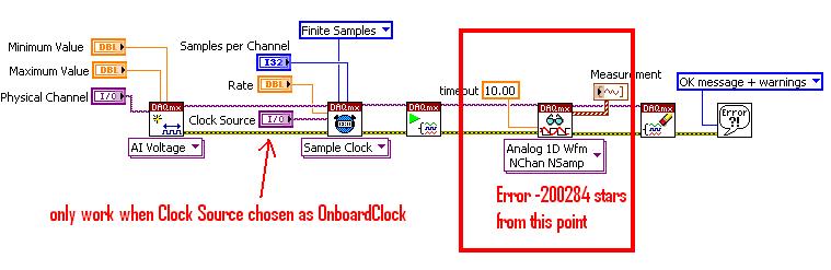
I open a new .vi and use the DAQassist. From there I select entry counter and then I tried the frequencies and Edge Count.
At the end of the day, either it usually gets me the following error message:
Error-200284 occurred to...
Possible reasons:
Some or all of the requested samples are not yet acquired.I guess that one I did most of the research is the counting of edge. It is continuous samples because I need to monitor the flow rate at the time rather than only to count the edges of time 0 until I stop the VI. So there are different ways to treat this error include changing the timeout value, something to do with 'samples to read' and 'sample rate', and then that it seems to me that I have to do: since the buffered continuous one requires an external clock, which is specified in the tab "Advanced Timing" of the menu properties DAQassist I have a lot of things to choose from. It seems/I/SampleClock or/ao/SampleClock is the thing to choose, but then several Web pages continue to say to make sure that the external clock is actually "run", or any word in this sense. So I tell myself, my external clock isn't doing anything and that's why reading isn't acquire samples. But really, I'm just lost. Then...
Question 1:
Is what I'm working on the best/right way to go about doing this?
Question 2:
How can ensure me that this external clock done everything what it is supposed to do so that I can get samples still for edge counting?
Well, my ignorance is exposed, please fire away. I have attached the .vi, although I don't think it will tell you anything other than I know how to click the mouse button when running LabView.
County Board is time since you don't have a sample clock. You can provide one from many sources, but in your case I suggest sticking to a task of frequency measurement I won't go into it now.
The frequency could be time for a number of possible reasons:
1. the external signal is not connected to the right Terminal (the default IS terminal your meter chosen if you not him have not overridden with a property DAQmx node which is not possible in the DAQ Assistant). For the 9422:
2. the signal may be connected to the right Terminal, but perhaps, it does not meet the specifications of the 9422 to be detected)<5V low,="" 11-60v="" high).="" you="" can="" verify="" whether="" or="" not="" the="" signal="" is="" being="" detected="" using="" a="" test="" panel="" (counter="" edge="" counting="" to="" determine="" if="" the="" signal="" is="" present)="" in="" measurement="" and="" automation="">
3 tasks of frequency are sampled off the input signal - so if the input signal does not switch when you start the program or if there is a long break (longer), you will receive the time-out error when the reading function blocks for more than your specified time-out. You should be able to just 'manage' the time-out error so that if it happens you can report a frequency of 0, ignore the error and try to read it again. There are also other approaches such as using events DAQmx or samples available to read to vote, but none of them are available through the DAQ Assistant (the idea is that you avoid making DAQmx Read blocking call until you know there are samples to read).
Configure a task of frequency is a better option for you, because it will give more precise (although you can set a task of County of edge to behave similarly to a frequency measurement task, this is trickier and you can also use the DAQ assistant). You can start out by setting 1 sample (on request) for the synchronization mode - this will return a single sample as soon as it is available. If you put the DAQ Assistant, in a loop, you will get a new sample at each iteration (or if your input signal goes, the samples will stop coming in and you'll get time-out errors instead). The downside is that you will not receive a sample on each side - entry task is reset by software and during this downtime between the samples will take no new data. This should be good for the case of the use you described (the frequency of a continuous square wave periodically monitoring).
So, make sure that the external signal conforms to the specifications of the 9422, and it is connected to the correct terminal (the PFI line which is equivalent to the DOOR of your meter by default). If your external signal is less than 0.2 Hz (1 sample every 5 seconds) you will need to move away from the DAQ assistant, as it seems that it is not possible to set the timeout of read using the DAQ Assistant (surprisingly). You might want to look in the API of DAQmx lower level anyway - here is a simple example to help you get started in the affirmative. It's really not too complicated and once you get used to it will be less heavy than using the DAQ Assistant.
Best regards
-
cDAQ HAVE task using external clock
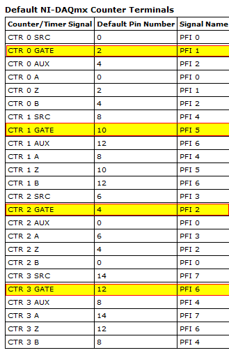
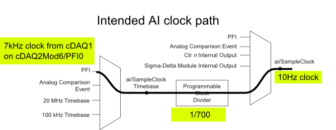
Hi, I am trying to use a clock signal on a line of PFI in order to generate a clock, but at a lower rate, for a task to HAVE. I run into many issues that I can't explain.
I have a cDAQ-9172 with an entrance module analog (9225) in the Groove 3 and a digital input module (9411 - 2 MHz DI) into the slot 6 (where the PFI lines are accessible). I want to use an external signal on et0/PFI0 to act as the clock for an analog input on the 9225 task. This signal comes from the cDAQ anothr chassis and is too fast for the task to HAVE it, so I intend to use the time base entrance and the divider to clock (as shown on page 31 of the cDAQ-9172 manual). See picture attached for a graphical representation of my problem.
If I have the wiring from the signal "/ cDAQ2Mod6/PFI0" in the DAQmx timing VI, get the error 200414 saying that "required sample clock source is not valid." It is strange because it is listed as "Direct route" in Max (the VI of polymorphic DAQmx Timing is configured as 'Sample clock') Q: why this route is not suitable for the task?
If I use DAQmx Timing property node and change the Source 'Sample clock Timebase' to ' / cDAQ2Mod6/PFI0 ", the task starts without error, but the separation seems to be forced to 256. If I try to change the properties of the separation of the time base, I get error-201100. Try to change the 'sample clock rate"doesn't have any impact on the task and the remains of divider"256 ". Q: why the 'Programmable clock divider"locked to 256 when using the PFI line or can you just not program directly?
I came across another error is the minimum speed on the PFI line. If I have the wiring (for the SamplClock Timebase) lower at 1 MHz, LabVIEW returns error-200077. The error message indicates that the minimum value is 1 MHz. 9172 manual shows the clock 100 kHz is an option for the time base, certainly less than 1 MHz. Q: What are the limits of upper and lower frequency for a clock signal on the line PFI for the ' Timebase AI/SampleClock "?
I looked on the site and in the DAQmx documentation for further explanation, but I have been unable to explain these strange behaviors. What are the barriers to entry of Timebase PFI and the time base "Programmable clock divider" preventing me to reach my goal here? If I can't do it directly, can I use the PFIn signal to feed an internal counter (to act as the clock divider) which could then generate the clock WAS at the rate I want? This method would allow me to perform a division arbitrary clock (unlike the ' 256', which seems to be forced on the PFI as a Timebase SampleClock.)
Finally, something seems odd that I can make an acquisition to 10Sa/s max but when I start a task using an internal timers of the cDAQ9172 and ask a 10Sa/s rate, the task really gives me a rate of 1612.9 sample/s while using the 12.8 MHz clock and a divider 7936 timebase. Q: Why can't the task to 10Sa/s?
I use DAQmx 9.7.0 and LV2012 SP1 (and I tried with 9.7.5 but I got the same results)
Thank you
Olivier
I got additional help Friday in another engineer at NEITHER and the solution to my original problem is actually very simple to get the clock from an external source path:
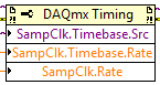
The idea of picking a PFI line for the basis of 'time' and the 'Programmable clock divider"(in fact, DAQmx calculate this number based on"HAVE sample time clock"and"Sample clock HAVE") works by using the node property below:
(SampleClock.Source cannot be resolved until the task is clerks/reserved, but the default option seems to be the time base that works well in this case.)
The question that I described earlier with the 9225 comes the module properties and the fact that it is a "Module of Sigma - Delta". That the module usually generates its own time of 12.8 MHz base clock (page 14 of the document 9225 # 374707) and the clock divisor is much less possible values than the other modules (must be a multiple of 256). It may use a different time basis from a PFI line, but it must be between 1 MHz and 13.15 MHz.
So a main clock between two chassis and tasks running at different rates of sharing should be easy and simple with most of the modules. With AI modules with Sigma-Delta converters add additional limitations and the master clock for the time base frequency must be selected to accommodate these module as well.
Another good news is that the Simulator seems to bear all these details and DAQmx (9.7.0 in my case) generates the same errors when you use a simulated chassis if you use real body. Play well!
-
To use the external clock for SCTL myRIO
Hi people,
I'm trying to find a way to get a 2.5 PSM 16-bit ADC, TI ADS1602, to send data to the device myRIO. Ideally, I'd like to bit Records at 40 MHz in order to obtain the benefit of the PSM full 2.5. I know that I can create an 80 MHz SCTL on the FPGA to create a clock of 40 MHz, but when I checked the clock on an oscilloscope signal, it was obviously greatly degraded by bunch speed limits, so he looked more like a sine wave to a square wave. I doubt it would work for use as a clock signal to drive the ADC since ADC specifications say that eligible jitter is around 100ps.
I can use an external oscillator to drive the ADC, but then I have to find a way to sync the clock with clock FPGA 40 MHz. is there any kind of PLL structure that would allow me to sync the clock FPGA myRIO to an external clock? Is there a way to do a loop simple timed cycle driven by an external clock? Or if I was able to customize the FPGA personality to accept a SPI signal up to 40 MHz (ten times her supported limit...), he would be allowed to use an FPGA to ~ 160 MHz and tell him to taste the SPI line each loop and proceed from there?
Thank you!
Hi 3.14159... ,
The myRIO doesn't have the ability to import a clock to use on the FPGA block diagram for clock loops timed cycle unique (SCTLs). The sbRIO-9651 new coming out week OR (not shipping yet) is the only sbRIO who has the ability to import an external clock in LabVIEW. Many of our products FlexRIO also have this ability.
Like you we have it, you can taste the signal at twice the frequency (or maybe more) to and wait an edge trigger to run a certain element of logic. "" "If you open the example Finder and navigate to hardware input and output" R series "FPGA Fundamentals ' triggers and guard dog" trigger detection, this gives a simple example to do this. Once again, since you are eager to taste 10 times the frequency of support, all bets are off, but it may be worth trying.
-
I recently bought a 7811R. I have a need to synchronize the external clocks (requires 3 in fact). How to set up external clocks for the 7811R in Labview FPGA modules.
Emax,
Unfortunately, not all FPGA target supports this feature. Currently, the R-series cards are not able to do. However, FlexRIO target supports using resources DIO as an external clock, including the following models: 7951R 7952R, 7953R and 7954R.
What components you try to synchronize in your application and how fast your clock do you have to go?
-
None of RNS, te0 & te1 clock source work except OnbordClock for cDAQ9174?
acquisition system used: cDAQ-9174, NI9206, Labview2009, OR-DAQmx 9.2, MAX 4.7.1
Referring to the "specifying different sample rates for CompactDAQ Modules multiple", following time engines could be used for cDAQ9174 (AI, te0 & te1)
/ cDAQ1/I/SampleClock
/ cDAQ1/TE0/SampleClock
/ cDAQ1/TE1/SampleClock
However, for the voltage-Clk attached Acq Select.vi, none of the above clock works unless OnbordClock is selected. Can someone explain this please?
Hi NCLbingji,
'Source' entry "DAQmx Timing (sample clock) .vi" tells DAQmx to get the sample clock a PFI PIN or another subsystem (such as AO, DIO or counters). It has not been designed to choose what sync engine to use. I think that the example of the community that you mentioned is defining the sample clock source incorrectly.
On a device with a single timing engine of HAVE, like cDAQ-9172, ' IA/SampleClock' by specifying the source of the sample clock I tells DAQmx to deliver the sample clock GOT to the sample clock, which he cannot do it, then it gives you a more useful error:
"Error-89131 occurred in DAQmx start Task.vi:8 '.
Possible reasons:
Attempted to perform an itinerary when the source and destination are the same terminal.
In many cases, like when you configure an external clock or counter source, you must select a PFI, PXI or RTSI trigger line as the terminal of the source.
Property: SampClk.Src
Property: SampClk.ActiveEdge
Source device: Dev1
"Terminal source: AI/SampleClock.A cDAQ-9174, DAQmx chooses the timing engine when you book the job. The timing engine he chooses does not necessarily match the timing engine that you specify in the VI. If it does not match (for example your VI specifies te1/SampleClock, but DAQmx choose te0), then your task will wait for Terminal produce some clock pulses. Because there, there is no clock on this terminal, the task eventually times out and returns the error-200284 (samples not yet available).
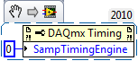
The correct way to explicitly specify what sync engine to use is to set the SampTimingEngine property.
Unfortunately, the table of values for this property by using NOR-DAQmx for 9.2.x version is also incorrect (reported to R & D such as CAR #239502). Here are the correct values:
- 0 selects te0.
- 1 selects te1.
- 2 selects HERE.
You can also leave DAQmx choose a timing engine, then ask that you chose. To do this, choose the task and then get the value of the SampClk.Term property.
Brad
-
Equium L20-197: no not line-in jack - how to record from an external audio source
Hello
I am generally very happy with my Equium L20, but I now find some trouble which I assume are from cost reduction. For example, there are no micro shipped, so need to buy one for Voip purposes. And I would like to use this notebook to record from an external audio source, but now to discover that he has no line-in, and it seems that the microphone jack is mono only, even if it was possible to configure the audo map to use this to source line.
I would be very grateful if anyone has any ideas for a solution workaround, possibly using a USB port.
TIA
KeithHello
What this USB external to the line adapter:
http://speechtechnology.stores.Yahoo.NET/am--USB--adapter.htmlThe adapter is especially useful for laptops or computers that do not have a Line In Jack or is not good sound cards
-
External clock as a time base (NI PCI-6122)
I use the PCI-6122 card and you want to provide an external clock very specific (preferably 10 MHz) as a time base. I tried to connect my external clock signal to PFI - 8 and then internally of PFI-8 road to the RTSI-7, but it did not work. I use only one card, and have therefore no beeing rtsi cable installed.
Can you help me set up the card to use my external clock?
Thank you for your help. It seems that there is no way around and I have to 'spend' an additional signal generator (locked my 10 MHz reference) to provide a sample clock, locked in my experience.
Maybe you are looking for
-
When I closed and reopened my PC all my previous mail disappears. How can I stop this?
With outlook, all mails have been identified, when I started the PC, now when I run Thunderbird starts with empty folders outside of "Deleted". How can I keep all messages in the po box until I delete them
-
My question says it all. I click on the new tab button and nothing opens. By clicking on the links will open a new tab, if necessary, or using "Open in new tab" seems to work very well.
-
Why Mail displays Messages of more than 15000 download when I deleted all the?
I'm new to Mail on Mac... When I run Mail activities area below shows an incremental number to download the messages. The number is currently over 15,000 but I deleted all messages in all mailboxes mailbox, even the spam and junk e-mail. What I am
-
How the interface telnet or PuTTY or plink software Windows with LabVIEW
Please find the screenshot attached screen of the problem that face here. He is, can't open the telnet session by using the IP address of the DEVICE. But after that am not able to send commands or argument to the PuTTY or plink. Exec System does not
-
My ports show to the MAX, but not available in my chasis lvproj using the scan Mode? All other modules work as expected. I've used this module mode of scanning in another chassis, but the 9146 is new to me. I did a series of loopback connector and r