Phase difference
Hello
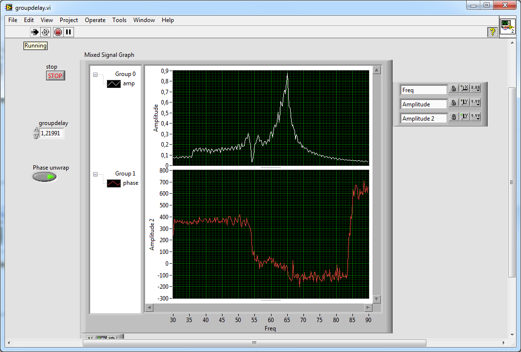
I would draw the difference in phase between two signal(input-output), the method that I use currently is taking "TNI" and (r-teta)... and by subtracting the phases, but what I get is not so desirable, do you know any other option or a suggestion to improve my results?
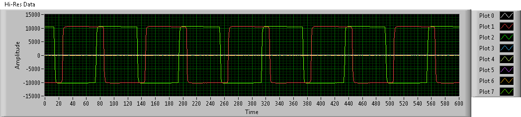
I joined the plot and marked them, one of the "FFT-magnitiude vs. output frequency" is as you see it is acceptable, but another "phase shift vs freq" is not so good.
Thank you
Petar
Here is a short play around phase unwrapping a > 1 s groupdelay?
What and how will you measure?
Impossible to open your code... always stick with an older version here
Tags: NI Hardware
Similar Questions
-
Measurement of Phase difference of audio - learning how to set the reference
I'm trying to measure the difference in phase between two audio inputs. (Left and right channel of my sound card)
Both are free running 1 kHz audio samples that come in and out of phase.
When the samples are in phase, everything seems to work fine and shows no phase difference.
However once that signals start to emerge from the +-10deg phase the result keeps jumping around.
It seems to be the fact that it is changing the reference to determine the phase.
When I view the phase of the output of a channel is a sawtooth waveform, from 250deg and then wraps round to-110deg
What I want, it's an entry set to 0 degrees and see the other inputs of difference of phase against it.
Is there a way to give a signal as being the reference or another strategy?
Thanks in advance for any help.
PLEASE NOTE THAT THE acquire.jpg IS ACTUALLY THE VI.
It wouldn't download like the vi. Please rename extension to acquire.vi to see.
Finally managed to find the problem.
Red rooster, I tried to replace your entries simulated with audio inputs card his real world and things turned out horribly.
It doesn't seem to be a translation between the two. (Perhaps because of my understanding of Labview garbage)
LabVIEW uses the internal reference of the DAQ cards in order to make phase measures.
That's what all use the phase VI of measure and which lack of cards not NI - DAQ.
That's what I thought that missed me first place but there's no way I can see simulations your own.
To work around the problem, I used zero crossing detectors in order to compare the time ahead or lagging behind the benchmark for the calculation of phase.
I got the core of the detector from somewhere on the forum but have lost the actual page. (my apologies to the author who deserves the credit)
Anyway, hope this hepls someone.
-
Caculate phase difference between two sine waves
Hey guys
Im having problems with this. I read most of it-related topics, but none of the solutions posted helped me.
I have this small circuit and im taking a few values of voltage using my pc sound card. Data acquisition works well. As you may know, the sine wave read in Terminal resistance has a different phase compared to the dinna wave read to capacitor terminal. I tested the file VI and I can confirm it in the charts that I see out there.
I had trouble identifing the difference in phase (in degrees) between the two waves.
I would appreciate if you could help me with this. Here is my file of VI in case someone can give me some suggestions on how to calculate the difference of phase in degrees. Also, in this VI, there are some tests I did with no good result at all.
Any help will be appreciated
Hi moreins,
I changed the code, check it! I gave two solutions that somehow work to calculate the phase difference.
I would like to know if this solution works for you or not. Good day!
Sincerely,
Krisna Wisnu
-
Questions about circuit RC phase difference (possible timing problem)
Hello
Here is the program that I use to measure the phase difference in an RC circuit. Simply generate a sine wave of 2 kHz in LabView and send it to the circuit using an analog output. Then I measure the exit sinusoid using an analog output. I also measure using n oscilliscope. I can clearly measure the difference in phase with the oscilliscope and know that it is about 1.4 radians.
Problems with the program:
Phase difference different measured each time the program is run for the circuit. It is never as good.Possible causes:
You will notice by looking at the vi that I measure the phase from the signal generator. Can I use a second analog input to measure the sine wave, as it came out at the beginning of the circuit?
I think it's a timing issue. While the phase difference is constant each time the program varies each track. So the time that each measurement of tone starts its first measure seems to be different every time and causes this reading of different phase.
The card that I use is a PCI-6221, is there a timing problem associated with switch for input and output audio acquistion or are they separated.
Is anyway to ensure that two key measures measure phase at the same point in the (real) time?
I would really advice or changes to the program - could someone offer me (I am a student and LabVIEW is not on our program so I have no support, but I use it for my project (OH!))
I would certainly acquire two signals. Food for the analog output right back into an analog input, then your signals filtered in another.
Initially, I would feed the two analog inputs of the analog output and measure the delay in phase due to the multiplexed A/D on map. Once you have this measure, you can feed in the filtered signal and then measure the difference of phase of this signal.
-
The best way to draw the difference of phase vs. time of two signals
I have three channels (time, force, displacement) of approximately 1 000 seconds of a sinusoidal test load test data (sampling rate was 100 Hz). I would draw the difference in phase between the force and displacement (perhaps using a second window 30) according to time. I tried using a few different analysis functions, but I get what looks like random noise (phase difference between force and displacement is very small and the difference in amplitude is very fantastic - 4 orders of magnitude). Any suggestion would be appreciated! -Jim
Hi Jim,.
The phase channel resulting, that you get with the function FFT DIAdem is in the frequency domain. If you select a channel data and time in the FFT dialog box, you will get a frequency channel that results as well as the Phase channel resulting. If you select only a weather channel of waveform data in the FFT dialog box, you will get a Phase of waveform frequency channel resulting.
Brad Turpin
Tiara Product Support Engineer
National Instruments
-
Square wave generation phase offset problems using PXI6602
Hello
I'm generating 2 signals using an incremental encoder AB using a PXI6602 to simunlating.
Signals must be offset square wave, 34,133 Khz, by 90 degrees, which I'll put dividing (1/frequency) into 4 and put the result in the knot of late initial .vi DAQmx create channel (frequency impulse Co generation).
Resulting signals phase difference however does not consistantly measures 90 degrees. 1 in 5 rounds of the vi has at least a matter of resulting in a test phase angle has failed.
Can someone suggest a stable solution for this.
Thank you
David
John_P1,
After posting the previous comment, I went back to play some more with him, and he now runs and returns a positive result every time.
The change that has had the desired effect was for the type of trigger that I had selected (Advance Digital Edge). Change this to start digital dashboard whose value fall of dash, the error disappeared.
Feel free to always criticize the vi and suggest / modify to improve stability / efficiency.
All feedback is voluntarily accepted

Thank you
David.
-
I have a 9174 OR compact DAQ with an NI 9234 and a NI 9269.
I am in a position two accelerometers with the NI 9234. I get forms of appropriate wave and RMS values, but I'm unable to measure a good phase.
I don't mean to measuing a phase difference! I can do that already, and this isn't a problem (and not really valuable information).
I'm looking to measure the phase for one (or all) provided waveforms. The phase of an accelerometer is important.
While I can read a measure of phase (I tried two ways), I was not able to find a way to get a reliable measure of phase. NI Calibration documentation says to use the "extract only your Information.vi", but it puts my phase in all directions. The waveform is rolling, and so each measurement is varied. Using a FFT block provides a more constant value, but it is varied same function where he thinks that the waveform is being in graphic form.
The NI 9234 is a Module IEPE without integrated analog trigger capabilities, so I'm a little confused on this one. Examples/thoughts?
Thank you
Billy
Hi Billy,
I don't know exactly what you're looking for, but there are a few screws designed for phase measurements.
You have the Sound and Vibration Toolkit? If so, Gain of one-shot, stage, & measure of distortion may be what you are looking for. The SVT Gain and Phase VI or Amplitude and Phase VI spectrum can do. Again, you can have not these although according to tool boxes that you have installed.
Hope this helps,
Chris G
-
Synchronous channel multiple acquisition USB-6259 (phase measure)
Hello!
I want to create a user-signal (1 k at 20 kHz) in SignalExpress, generate it with the case NOR USB - 6259 BNC and measure with the same device after that the signal has passed a DUT I need the answer for a fixed term.
For the moment, I'm trying this: I connected the output via a Y-coax analog (length 1 meter) to TWO analog inputs.
Because the input channels have been grouped with the add a channel button, the data acquisition should occur almost synchronous.
However, sometimes the phase response is zero (cause as expected the two signals must be equal), but sometimes it "jumps" (especially when I am running the new project) and increases or decreases linearly on the frequency (so there is a time difference between two measured signals).
I don't think that running is the problem here, because referring to the manual, it's about some µseconds and I have not yet change the range of voltage between input channels. Furthermore, the magnitude response is fine.
I has not yet perform to synchronize the input channels with the output of the channels either, but first I would be recognizing a solution for the entry-entry-synchronization, (I don't mind if it is implemented in LabView).
Thanks in anticipation, Daniel
Hello Daniel,.
the M-Systems Series DAQ using a switch to sample multiple channels. So you have to take the time to switch into account when
you do measures such as phase shift of two signals.
I took your project Express of Signal but also created a LabVIEW VI to double check, and you can see exactly the same lag between the two
sampled signals. If you want to measure the true phase differences, you have to use a device of simultaneous sampling like S or DSA series devices (there are more a few others).
concerning
MArco Brauner NIG.
-
Electrical engineering. Delay or phase of divergence of a voltage signal acquired by RedPitaya.
Hello!
I work with Labview and RedPitaya in order to measure the voltage and current to calculate the instantaneous power lift consumes when it works and then see how many are P active and reactive Q.
I need to measure the voltage between line and neutral and multiply it and current, the problem is that the neutral is not accessible, so I have to measure the voltage from line to line and turn it into the phase voltage line.
In order to realize that I have to make two changes.
(1) I have /sqrt3. I have already done without problem
(2) I have to define a phase difference of 30º, or delay of a period that is equivalent (1,6666667 ms) for the voltage signal.
I tried to do this using a block to wait a certain time structure, but it does not work correctly when the voltage needs a loop, because the Subvi does not work at the same speed, during the reading of current and voltage after a delay I see with the option to highlight. And all the clock, wait or delay the blocks I've seen are supposed to work in a loop, not connected to a signal that reads / acquisition of an instrument.
Is it possible to affect this difference in phase or equivalent delay without a loop that only affect the voltage signal?
Thanks in advance.
Did you just ask to all samples, then throwing those that you don't need? For example, let's say that you are sampling at 10 kHz, if each sample corresponds to a period 100us, 16 equals 1.6ms samples and so on. So you multiply 0 line 1 (0 indexed table) sample, for example 15 or 16 of the line 2 (the one that it works best for ya, or an average of 2) and use it as your result. In this way, you don't need any delay whatsoever and do not have to worry about synchronization, since all data is coming at the same time
-
Is it possible to simultaneously use both inputs like antennas?
Hallo,
I would use a USRP to measure the phase shift between the 2 RF signals to about 101 MHz.
Is it possible to use only a single USRP and use the RX1 RX2 simultaneously perform this measurement of phase difference?
Thanks in advance for your answer
Stone
That's right,
Two USRPs and a MIMO cable or an external clock of 10 MHz with PPS output. We use a combination of both in our demo MIMO 6 x 6
-
To input analog shutdown when the analog output is completed and synchronization
Hello
I'm trying to get my LabVIEW program to send analog output to a computer and read acceleration using the cDAQ-9184. Chassis output that I use is the NI 9263 and the chassis of entry is the NI 9234. I generate a signal of white noise using LabVIEW Express signal generator.
The first problem I have is the synchronization. I had an old VI that has begun to measure the acceleration just about a second after the entry has been given to the machine. I used the LabVIEW tutorial on how to sync the analog input and output, only to discover that it does not work with two different hunts. Then I found another tutorial that shows how to synchronize different frames between them.
The second problem is the cessation of the LabVIEW program. What I want to do is to generate the signal and then simultaneously send and read the input and output analog, respectively. It is because I don't want a phase difference or any shorter signal for a direct comparison. But as soon as the signal is sent to the machine, I want the entry to stop analog playback and then then the LabVIEW program must stop. I want to be able to choose any length of signal to be generated and stop as soon as the entire duration of the signal has been sent to the machine.
I tried 'DAQmx stop', "DAQmx Timer" and 'DAQmx's task made?' and none of them have worked for me. It is also my first time on a forum posting, so I hope I gave enough information. I enclose my VI as well. The VI shows I read an entry for the analog input voltage, but I am only using this to try to get to the work programme.
I'd appreciate any help I could get.
Thanks in advance
Peter
Hi Peter,.
I have some recommendations for you that I think you will get closer to your solution. First of all, I assumed you meant that you had 1 chassis (cDAQ-9184) who had two modules in it (NOR-9263 and NOR-9234). My next steps are based on this assumption, so if it's wrong, please let me know.
For your first question about the synchronization, the code you provided is very close to what you need. You need to do, however, implement architecture master/slave for startup tasks DAQmx functions. To do this, you can add another frame to the flat sequence structure and put the master start task (input voltage) after the start slave (output voltage) task.
To manage your second question and that the program ends at the point where you, the first step is to get rid of all the logic that you use with the local variable of length of time. Rather than use this logic, just wire the node "task performed?" of "is task performed?" operate to stop the loop. This will cause your loop to stop as soon as the signal is sent to the machine.
I have some other recommendations for you that will increase the performance of your program:
(1) rather than writing on file inside the last loop, you can use the DAQmx Configure Logging (PDM) .vi. You will place this VI between DAQmx Timing.vi and DAQmx Start Task.vi to the task of the analog input voltage.
(2) after the last while loop, you want to stop the task and analog outputs as well with another DAQmx stop Task.vi.
(3) rather than using a local variable for the entrance of displacement and wiring it in the DAQmx Write.vi, you can wire directly from the output waveform of the wave to build function node.
That should help you get started in the synchronization of these tasks.
-Alex C.
Technical sales engineer
National Instruments
-
Hi, I want to use three USRP to communicate with each other. But I met the question of frequency offset. To eliminate the frequency, first of all, I want to use the external clock
to synchornize three USRP. I know I should use REF in the Port, but I want to use PPS to?. In addition, there good ideas to reduce the frequency shift? I'm a newbie to USRP, answer you will be highly appreciated.
Hi llg9012,
There are 2 ways to synchronize your USRP. If you have only 2 USRPs, you can use a cable MIMO to share the reference clock and clock PPS between the 2. Since you have more than 2 USRPs, you will need to provide a reference clock (10 MHz) and a PPS (pulse per second) clock all 3 units. After you have plugged them in this way, you will have to use a property node to set the reference clock source and the time base clock source (which is the clock PPS) external.
Sharing these clocks will keep the relative phase between all 3 constant signals. However, whenever you stop and start the device phase differences will not be the same. If you are only concerned that your frequency and phase without drifting through time, using external clock sources is the best solution. If you need your USRPs 3 to have the same phase, you can use a sequence of training to align the phases. There are posted examples here the community that can be useful for your work request:
https://decibel.NI.com/content/groups/NI-USRP-example-LabVIEW-vis?view=documents
Discover the angle of arrival detection and 6 x 6 examples MIMO to see some examples of how others are synchronize their USRPs.
-
[FlexRIO] Start-up to synchronize several clocks sample
Hello
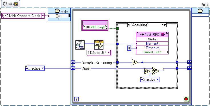
I tried before, two different (SMU-7962R + OR-5734) FlexRIO card reading in the '40 MHz Onboard Clock' or 'PXI_Clk10' areas of clock. Trigger has been achieved by simply looking for a rising edge on PXI_Trig0:
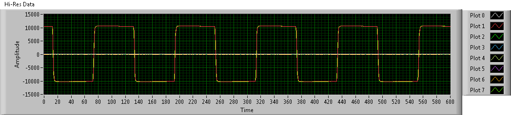
This produces seeds, but there has no inclination (or constantly tilt at least) between the two FlexRIOs - I sent a pulse train duplicated in the two cards, and the triggered-acquired waveforms were still at the stage:
To avoid problems, I went to examples of clock (IO Module clock 0). Unfortunately, the clocks of the sample between the two FlexRIOs had nothing in common, so the acquired waveforms have been is out of phase. Worse still, the phase difference changes with each release:
Looking at the implementation of the library of the synchronization of the FIDL, the classic technique for synchronization of multiple cards FlexRIO seems to be built around synchronization master-slave (my observation is correct?). I was wondering: is there a way to simply share a sample clock shared between cards (like what the 40 MHz embedded clock was doing before), as described in http://www.ni.com/white-paper/11369/en/ ? (I think I understand the disadvantages associated with sample clock synchronization, but I'm willing to try for now).
Thanks in advance!
Hi JKSH,
Page 9 of the Manual 5734 described the different synchronized methods that can be used the 5734. You can synchronize either sample clock of each module to a clock available through your chassis backplane (for example, DStar_A) by allowing the IOModSynClk in 5734 properties (available the Details category) or use an external clock through the Clk port on the module. Activation of IOModSyncClk is probably the best approach and will lead by examples of clock on each module e/s being PLLed on the clock of the town - which must synchronize the clocks of the two sample together.
Let me know if you have follow-up questions.
Kind regards
-
Hello
My value of phase difference (phi) is not updated if I change my phase of input values. Everything is updated while the loop runs. I need to stop and restart the vi just to update the value of phi.
Can someone please.
Signal generators only look use the Phase on reset input. So if you want to phase in order to change, you need to reset the signal generators.
-
Hi all
I'm doing a school project and I worked on a vi to measure the phase difference in an RC circuit. I excite a sine wave to approximately 2 kHz of LabVIEW. I then measure the output with two analog inputs to the terminals of the resistance. There is an inconsistency in the measured results.
I know that the actual phase difference to be 1.5 radians, however when I run the program I get a value between 1, 5-1, 75 radians (this value varies whenever the program is executed but remains constant for each race). It could be down to delay multiplexing error is not compatible, so I don't know how to realize.
It was suggested on the forums to try a lower level vi and this is where I feel great difficulties. I can't seem to get their work and have no experience with them.
Here are two vi. The first my vi express and functional. Second my 'attempt' to be converted to traditional vi.
Could someone please take a look at them and help me to identify the problems, I'm almost out of time for my project, so I don't have much time for my usual trial a 'mistake' approach)
I was not able to get to the lab during the Easter holidays, so a question I would ask is I can choose two-way analog inputs of this set to the top?
The last time I tried this put in place that I wasn't getting any data on any of the vi in the loop. Not even on the graph of measure.
Kind regards.
Hey Jackthelad!
I may have missed something here, but I think that the following code always piece will generate a 0 (zero). You take the same data to a single channel, which analyzes the data, and then subtracting the phase to each other. But because you analyze the same data twice, it will always result in 0. Is that what you think?
If you need to read from 2 separate channels, you have to modify the code to modify the code to look like the following.
I've also attached the .vi.
Hope this has been useful.
Good luck with the project,
Maybe you are looking for
-
HP 15 laptop: my laptop screen has touch capabilities whether and how to activate it?
Windows 10 Product no.: L0T31UA #ABA Model: 15-f209wm
-
update to airport utility to el capitan
bought 2 GB time capsule dual band 802.11n Wi-Fi and I try to install the software disc supplied (versión2.0, 2Z691-6486-A) on my macbook pro 2009. but can't get as fa like this warning screen "Airport, t utility installs on this disc (El Capitan). T
-
I currently have my LOCK button of the LETTERS on the image below, but I don't know how to use this command. I thought that meant that when I pressed the button control as you type, everything would come out CAPS. Can you tell me what this change? Th
-
Why 'Read a fixed number of samples' help with the error 200279?
Hello world It is a question about a tip found in the explanations on the acquisition of data error-200279. This explanation it is said: '... ". reading a fixed number of samples instead of all available samples can fix this... » AFAIK the DAQ system
-
Help me with this blue screen!
My computer has been infected with control of HARD disk about 12 hours ago, and I tried to remove it with Malwarebytes, but when he scanning, virus above toke and shuts down my computer. When I tried to restart, a blue screen appears indicating A pro