Electrical engineering. Delay or phase of divergence of a voltage signal acquired by RedPitaya.
Hello!
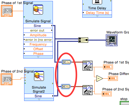
I work with Labview and RedPitaya in order to measure the voltage and current to calculate the instantaneous power lift consumes when it works and then see how many are P active and reactive Q.
I need to measure the voltage between line and neutral and multiply it and current, the problem is that the neutral is not accessible, so I have to measure the voltage from line to line and turn it into the phase voltage line.
In order to realize that I have to make two changes.
(1) I have /sqrt3. I have already done without problem
(2) I have to define a phase difference of 30º, or delay of a period that is equivalent (1,6666667 ms) for the voltage signal.
I tried to do this using a block to wait a certain time structure, but it does not work correctly when the voltage needs a loop, because the Subvi does not work at the same speed, during the reading of current and voltage after a delay I see with the option to highlight. And all the clock, wait or delay the blocks I've seen are supposed to work in a loop, not connected to a signal that reads / acquisition of an instrument.
Is it possible to affect this difference in phase or equivalent delay without a loop that only affect the voltage signal?
Thanks in advance.
Did you just ask to all samples, then throwing those that you don't need? For example, let's say that you are sampling at 10 kHz, if each sample corresponds to a period 100us, 16 equals 1.6ms samples and so on. So you multiply 0 line 1 (0 indexed table) sample, for example 15 or 16 of the line 2 (the one that it works best for ya, or an average of 2) and use it as your result. In this way, you don't need any delay whatsoever and do not have to worry about synchronization, since all data is coming at the same time
Tags: NI Software
Similar Questions
-
measurement of phase shift between two periodic signals acquired
Hello
I don't know how to explain my problem, but I'll give it my best shot. I'm two signals from sensors in tension. Two periodic signals have the same frequency, but a different amplitude. Normally they have a difference of phase of 0 or 180 degrees. The thing I have to let labview to check is if the signals are completely in phase or out of phase (180 degrees) completely. I am acquiring the wizard scene DAQ in a while loop. Does anyone have an idea how I can do this?
To summarize: are the two things I need to know
-l'amplitude (maybe just pick max max min distance)
-If both signals are moving in the same direction (when the two signals are in phase) or if they move in the opposite direction (counter phase) - the exact phase angle value is not so important
THX
Thanks for the reply. After a night to think about the problem, I came up with a home-made solution. I used the point by point max and min vi to calculate the distance from crest to crest of my signals. Then, I used the time derivative of point by point to calculate the variation of the signal of the two signals. If the signals are in phase (both are increasing or decreasing at the same time with the other), then the two derivatives have the same sign (accept on the summits, of which I have excluded from the comparison). If the signals are out of phase (when one increases, the other is decreases and vice versa) then the two derivatives are opposite in sign. According to this, I can get all information that I need. If anybody should know a better way to achieve the same result, please say, but to know that it seems to work.
-
NEITHER 9215 delay in phase between two channels
Hello
I use Ni9215 with ENET-9163 to measure the phase between two sinusoidal incremental signals delay. First signal connected to AI0 and, secondly, to AI4 at 100 k sample rate. I know 9215 simultaneous ADC, but it seems to me that NI 9215 gives additional time between the channels. Is it possible, or l mistaken?Alexandr.
Hi Alexander,.
Please let us know how you get on,
Chris is correct - with the idea of using a right signal to both channels, I tried to suggest this earlier...
I hope this helps with your problems with delays,
-
variable phase shift between two analog output signals
Hey! I would drive two different piezo elements with an sine - / square signals and have a phase shifted output signals. After some trail and error, I was able to get a second analog output on my card PCI-6221 (using LabView 8.2) also allowed me to have different amplitudes for both signals. However, I could not output signal having a frequency different and most importantly to my request to have one of the signals variably shifted phase.
Thanks for the very useful suggestion. I have attached the file .vi installation I've run so far.
Hello!
A way to generate waveforms is using the analog waveform Toolbox. I created an example VI that is attached and that shows you a way to use the base generating function VI. I saved for LabVIEW 8.2.
I hope this helps!
-
Questions about circuit RC phase difference (possible timing problem)
Hello
Here is the program that I use to measure the phase difference in an RC circuit. Simply generate a sine wave of 2 kHz in LabView and send it to the circuit using an analog output. Then I measure the exit sinusoid using an analog output. I also measure using n oscilliscope. I can clearly measure the difference in phase with the oscilliscope and know that it is about 1.4 radians.
Problems with the program:
Phase difference different measured each time the program is run for the circuit. It is never as good.Possible causes:
You will notice by looking at the vi that I measure the phase from the signal generator. Can I use a second analog input to measure the sine wave, as it came out at the beginning of the circuit?
I think it's a timing issue. While the phase difference is constant each time the program varies each track. So the time that each measurement of tone starts its first measure seems to be different every time and causes this reading of different phase.
The card that I use is a PCI-6221, is there a timing problem associated with switch for input and output audio acquistion or are they separated.
Is anyway to ensure that two key measures measure phase at the same point in the (real) time?
I would really advice or changes to the program - could someone offer me (I am a student and LabVIEW is not on our program so I have no support, but I use it for my project (OH!))
I would certainly acquire two signals. Food for the analog output right back into an analog input, then your signals filtered in another.
Initially, I would feed the two analog inputs of the analog output and measure the delay in phase due to the multiplexed A/D on map. Once you have this measure, you can feed in the filtered signal and then measure the difference of phase of this signal.
-
Currently, I use version E Plan P8 1.9 on windows XP. I am buying a new computer with Windows 7 operating system and would like to know if plan will work on this new system?
Any help appreciated.According to the Windows Compatibility Center, it is compatible with versions 32 and 64-bit Windows 7: http://www.microsoft.com/windows/compatibility/windows-7/en-us/Details.aspx?type=Software&p=EPLAN%20Electric%20P8&v=EPLAN%20Software%20%26%20Service&uid=1&l=en&pf=0&pi=1&s=eplan%20electric&os=64-bit
In addition, their support site gives the requirements for version 2.1 (but I can't find anything to 1.9 or any updated information): http://www.eplan.de/products/electrical-engineering/eplan-electric-p8/system-requirements.html?L=1 -
difference of phase for LabView
Hi guys,.
I need help in this program I am writing. I'm trying to calculate the difference in phase between two different simulated sinusoids. I searched online and found out that I could do that using retrieves your unique information and subtracting one phase to the next. However, I struggle to connect the wires, and I'm not sure why he does not connect properly. Forgive me if this is a fundamental problem, as I'm new to LabView. Thank you. The program is attached.
aclx
aclx,
It would be probably better if you posted your question for the LabVIEW Board rather than the Board of Signal conditioning. This Board gets about 1% only as much traffic as the LV Board and your question has nothing to do with conditioning of signals.
You have two questions.
1. the Type of dynamic data (evil) generated by the screw Express mask all the information about what's on the wire. It seems that the default conversion performed by the entry to retrieve only your Information.vi was in a table of waveforms. This gives a picture of phases out. You can tell what kind of data is on a wire or why a thread is interrupted by pointing the cursor to tool of wiring on the wire with the open contextual help window.
2. the relationship of phase between two signals of different frequencies is not defined. What moment in time should be used as the reference? How acquired or simulated signals relate to that time on the iterations of the loop?
The first issue can be fixed by explicitly converting DDT to a waveform as shown below.
For the second question, you need to define what you mean by the phase shift of two different frequency signals.
Lynn
-
I have a digital trigger switch that is bound to a module OR. How can I know the amount of the delay from the trigger to the module or?
Yes.
AKA 0.00000305 seconds of 0.02 seconds trigger duration.
AKA 305usec off 20000usec
AKA 0.305nsec off 20000000nsec
It is up to your application if it is negligible. If the nuclear reactor will explode in 2 microseconds, unless this digital trigger closes its first down, you watered. Otherwise, good to go.
Nothing is instant, including all input signals you have. The propagation delay is on the front and down the signal, then the length of signal will always be 20ms, it will simply be moved by the delay of 3.
-
Problem with the generation of multi-sinus wavefrom of random phase using PXI-5412
Hello
I am trying to generate random phase multi-sine waveform using the PXI-5412 14 bits 100 M/s AWG on LabVIEW8.0.
The version of LabVIEW8.0 for the PXI-5412 comes with a sample VI on multi-tone waveform generation. When I tried with a different combination of frequency and amplitude, there is no problem with the sample VI.
Because I need the phase to be random for each frequency component, I had tore the tone cluster containing 3 elements, i.e. frequency, amplitude and phase, which feeds the generator of signals, and rebundle the cluster with elements of reading a CSV file by using a loop, a fixed value amplititude and a number of random phase of the frequency generated by a random number (formula lournies elements (: pi - 2pi x r). When the waveform multi-sinusoidale generated on the PXI-5112 100 MHz Digital Oscilloscope, it was pointed out that the waveform would change with the tested frequency range. However, the amplitude of the wave is always ~1.4V (guess that's always default to 1 V x sqrt (2)). There is no question also when testing the same combination of frequency and amplitude by using sample VI without modification.
Please find attached the VI of the sample, snatching up to the version and the CSV file I used. Is there something wrong with the table 1 d of the cluster of 3 elements that I built and assembled causing the signal generator to ignore the value of input amplitude and, possibly, the input value of the same phase (as it seems that the amplititude is always set to the default)?
The other question that I found on the two sample VI and ripped version is on the news of sampling. The waveforms appear on digital Oscilloscope PXI-5112 always default to 10 cycles no matter how changed the sampling frequency and the number of samples. For example, if the frequency is 10 Hz, sampling frequency is 1000 Hz, and I put the number of samples to 10000. I'm supposed to get 10000/100 = 100 cycles. However, I could see 10 cycles no matter how, I changed. What should be the correct way to change the number of cycles?
Really appreiciate your help and advice. Thank you.
1 phase unit is in degrees (-180 to 180), no - pi pi.
2 standardize Waveform.vi always normalize your amplitude of the signal. You can remove it to use your desired amplitue, but must make sure that it is not above 5412 spec. -
I can't generate multiple signals with different phases.
Hello community!
I created a simple signal generator versatile (see Signal "Generator.vi"). When I try to put two of these generators in the same VI ("testbed non working.vi"), I'm not able to independently change the phase of the two signals. Only one of the two phase buttons actually modifies the two signals, while it has no effect.
However if I copy and paste the exact schema even twice in the same VI, rather then import VI Builder, everything works fine ("Test Bench working.vi").
It seems to me that the two generators are sharing anything other than the phase variable. I'm new to LabView and I can't understand what is happening and how to fix it. Can you please help me understand?
Thank you very much
Hello
This is because multiple instances of the basic vi function generator will work regardless - they share information.
To fix this one true constant wire to signal to reset the basic vi function generator enter your generator of signals vi.
Best regards
Florian
-
Retiming does not not on surround sources
I have a problem using logic to reprogram cinema surround sources. I use Pitch' no time did a great job of Retiming of mono and stereo sources and working happily in ProTools, which we don't have.
But once a surround source is used in the logic and a speed control is composed, (such as-4% for the 25 > 24 fps Retiming) rebound resulting is the same in time to the source. This occurs using NTP and also one of the algorithms. Nothing works except mono tracks, which destroyed the Retiming of split engine block beautiful phase.
Anyone else had this?
In fact, I'm wrong - or perhaps in law in a different way - it seems to be the choice of Surround sound in the bounce dialog box that fires it upward, regardless of the source.
-
The first (emulator) HP: HP Premium differential equations
Hello
I'm looking a calculator with AC for my electrical engineering studies and just tested
the first emulator to get a first impresseion.
But while testing its features, I got some results of unexpectet on differential equations,
that I would be confirmed on a calculator of real world.A simple as equation y' = x
CODE: desolve (diff (y) = x, x, y)

wait-> x ^ 2/2 + C

First HP-> 1/2 * (x ^ 2 + 2 * C).
The result is correct, but nobody would write it down in this way, nor would one solve it how works the first.
A little more difficult equation could not be resolved by the premium: 2 x ^ 3 * (1 + y ^ 2) = y'
CODE: desolve (2 * x ^ 3 *(1+y^2) = diff (y), x, y)

wait-> y = tan (1/2 * x ^ 4 + C).

First HP-> could not resolve the implicit equation
It is not an implicit equation, the two WolframAlpha (iOS) and CASES of TI (iOS) could also resolve this one)
And last but not least: y' * sin (x) = y * ln
CODE: desolve (diff (y) * sin (x) = y * ln (y), x, y)

wait-> y = e ^ (C * tan (x/2))

First HP-> y = e ^ (sqrt (cos (x) ^ 2-1) / (C * cos (x) + C))
I don't know what made the CASE here, but there is no reason to use the Pythagorean trigonometric identity.
Would be nice if someone with a premium could conifrm/refute these results or tell me what I've done
evil.Hello
The latest version of premium can solve your 2nd test case (desolve ((2 * x ^ 3 *(1+y^2)) = (y'), x, y))
However, the results for 1 and 3 test cases are the same that you tested.
I will pass the info to the person who develops the CASE and if all goes well he will be able to improve it.
Cyrille
-
Premium HP: HP Premium: PROGRAM FOR DOING MATRIX OF BATTERY of the CALCULATOR (don't DO NOT WORK!)
Hello!
I attend the University for electrical engineering, and so I plan to buy a good calculator for my needs:
-programmable with enough memory
-graphical representation
-"Advanced" math
I have not discovered only recently on the amazing HP calculators (e.g. HP 50 g), which are capable of the RPN notation and thus make the calculations very fast and effective. I really hate the new calculators that announce the entry "quick and easy" using graphic symbols and cursor to select the location of the entrance! It of a lot of your time and makes me crazy, especially when it comes to long and "complex" calculations
As I am not able to get the new HP 50 g, I looked at his "successor": first HP. But unfortunately there many defects in the RPN notation and also in some functions. But I'm willing to compromise, especially if I can write programs to replace some missing critical functions of HP 50 G.
BUT, when I started looking into writing my own duties I quickly discovered that the lack of management functions of the inputs/outputs and even some strange/inexplicable behaviors.
I wrote a program:
EXPORT array()
BEGIN
LOCAL a, b, i, j;
a: = years (1);
IF length (a) == 1
THEN
b: = MAKELIST (years (X), X, a + 1, 2,-1);
ON THE OTHER
i: = a (1);
j: = a (2);
b: = MAKEMAT (years (i + j + 2 - J-(I-1) * j), i, j);
END;(b) return;
This program takes the last argument ("a") of stack for the size of the list/matrix.
If the argument 'a' is a number (list 1 item), it creates a list of the last 'a' arguments from the stack. -> WORK
Otherwise, it creates a matrix with columns and the specified lines. -> DOES NOT
Now when I tested the code without I or J arguments MAKEMAT service, she worked OK. He worked too, if I used a very simple expression: for example I have J-1 or i + j - J + 2 (column only scanning).
(The upper part (1
 expression in the stack is the return value after execution of Array ()))
OK LIST:
MATRIX not OK:
MATRICES OK, so current of enforcement only of years (i + j - J + 2):
MATRIX OK, so current execution really simple Ans(I+J-1) function:
Why these anomalies! I was really looking forward to buy HP Prime, but after all these issues and no real control on the stack of the calculator for the impressive programs

HP 50 g has built in functions for these conversions, but more recent first HP does not work.
All the best,
Ziga
And summarize the features of the program:
Make a list of last wrote the number (one being 1: command):
Make a matrix using a schema = {i, j} (a being list in 1: command):
The array() function:
EXPORT array()

BEGIN

LOCAL a, b, i, j;

a: = years (1);

(A) IF size == 1

  THEN

    b: = MAKELIST (years (X), X, a + 1, 2,-1);

  ON THE OTHER

    i: = a (1);

    j: = a (2);

    b: = MAKEMAT (years (i * j - J + 2-(I-1) * j), i, j);

END;

(b) return;
END; -
Solve this linear system HP50g
Hi guys,.
I am an engineer in electrical engineering and have to solve systems of linear equations on a regular basis, so that the functionality is very important for me. Everything works very well, 95% of the time but sometimes I meet systems that the HP50g doesn't seem to like. For example one below.
I want to solve for x, y, z and one in terms of V
V- 100000 x +is-100000 100000x= 0
-250000is-V+ 100000x100000z= 0
-250000z+ 100000one+ 100000y= 0
a+ 100000-250000z= 0
After these 4 equations is on the stack, I'm them in a vector by pushing {4} in the stack and then by pressing -> ARRY. Then I push the variables I want to solve for the battery, x, y, z and a and a vector of them. Then, I use LINSOLV to solve the system. However, when I do it this way, the calculator gives me an equation for x, an equation for y and 2 equations for z and no equation for s. I'm not sure what I'm doing wrong. Is there another way to do that would give me 4 equations, one for each variable I want to solve for in terms of V?
If my method to solve linear equations is somehow confusing, I basically followed this video
http://www.YouTube.com/watch?v=z802L29JyQE
Thanks in advance.Hello
Do not know exactly how you typed, so I'm being explicit just for some b:
Notes:
(1) as an equation is entered, use ' '
(2) it is preferable to use a comma to separate the real and imaginary parts
(3) explicit use multiply
If the entry will look like this:
'(4,3*X) = (4.7)'
For this simple equation and assuming that X is defined as an independent variable (reproduced by 'X' in the top middle of the screen), you can use SOLVEVX for this one: (No. 5 in S.SLV menu or F5 if you use soft-keys)
with "_Approx" uncontrolled, the answer is:
X = 7/3
with "vabout" checked the answer is:
X = (2.333333333,0) (although X is part of the imaginary number, it is himself a real number).
Kind regards.
-
50G and problem with integrals, new user.
Hello! I am a student in electrical engineering and I bought a 50G as my first graphing calculator, since that's what most teachers recommend here. I have colleagues who use the same who also make things a little easier, but I have almost no experience with it.
I serve the 49G and first emulators recently so get used to RPN, and while the first gives me the right answer, my physics 50 G and the emulator of 49 G give me something weird.
Well, if I'm trying to incorporate "exp (x ³) dx" for example, the calculator gives me "exp (x³t) dxt" on the screen.
Most of the integrals worked out of the box, but some have this exact same behavior.
Because the emulator of 49G and 50G physical give me the same thing, I suspect that it is just a matter of configuration. First emulator gives the answer however.
Here a few photos:
Then request EVAL:
And 49G emulator:
Thanks in advance, any help is appreciated.Hi!, JVChrisostomo:
IMHO, you need use the RPN MODE.
Configure...
Number format... Difficulty 5
Flags
01 main value
Function 03-> num
Mode approx. 105 on
Use EQW...
The result is... 5.96394E91 or 5.96394 x 10 ^ 91 (takes approx. 7 "with EVAL)
Check, using Wolfram closest to you. Alpha interpretation:
final integral(e^x^3,0,6)


Maybe you are looking for
-
Compaq 8000 Elite COnvertible: compaq 8000 elite minitour convertible pci driver windows 7
Hello, I had trouble finding the right drivers for my port of compaq 8000 elite series minitour convertible pci and pci simple communication controller, running windows 7 ultimate 64-bit... I found a link in a different thread, but the link does not
-
Equium P200 problem with WLAN networks
I recently bought Equium P200-1ED.When I m disconnected from the wireless network, computer laptop peut t reconnect himself and he can t see available networks. I have to restart my laptop to connect again.I checked the settings and everything seems
-
Pavilion dm1... screen pixilation
At the age of one year the screen has developed questions. Line appears on the screen, followed by a more serious rasterization of the screen that can make use of the laptop impossible. Question delete on reboot
-
CB280HK appears in 2K resolution.
The only available higher resolutions are standard (@60 fps) HD and 4 K (@30 fps) with nothing in between. Using cables with a double Setup dvi monitor, 9600 GTX 2 GB GPU chipset.
-
Channel-group is not working (via LACP) between 6624 and 6224F
Hi everyone, I need help. aggregation of links is not working. The following example uses the 6224 switches and 6224f 6224 interface ethernet 1/g23Auto mode channel-group 1Description "Ether_Conection".Disable spanning treeswitchport mode trunkswitch