Synchronous channel multiple acquisition USB-6259 (phase measure)
Hello!
I want to create a user-signal (1 k at 20 kHz) in SignalExpress, generate it with the case NOR USB - 6259 BNC and measure with the same device after that the signal has passed a DUT I need the answer for a fixed term.
For the moment, I'm trying this: I connected the output via a Y-coax analog (length 1 meter) to TWO analog inputs.
Because the input channels have been grouped with the add a channel button, the data acquisition should occur almost synchronous.
However, sometimes the phase response is zero (cause as expected the two signals must be equal), but sometimes it "jumps" (especially when I am running the new project) and increases or decreases linearly on the frequency (so there is a time difference between two measured signals).
I don't think that running is the problem here, because referring to the manual, it's about some µseconds and I have not yet change the range of voltage between input channels. Furthermore, the magnitude response is fine.
I has not yet perform to synchronize the input channels with the output of the channels either, but first I would be recognizing a solution for the entry-entry-synchronization, (I don't mind if it is implemented in LabView).
Thanks in anticipation, Daniel
Hello Daniel,.
the M-Systems Series DAQ using a switch to sample multiple channels. So you have to take the time to switch into account when
you do measures such as phase shift of two signals.
I took your project Express of Signal but also created a LabVIEW VI to double check, and you can see exactly the same lag between the two
sampled signals. If you want to measure the true phase differences, you have to use a device of simultaneous sampling like S or DSA series devices (there are more a few others).
concerning
MArco Brauner NIG.
Tags: NI Products
Similar Questions
-
I want to integrate the ANSI C sample program ReadDigPort - ExtClk.c in my own big package.
I want to use the internal clock of the BNC NI USB-6259 (.. 80 kHz 120 kHz).
In the document:
High speed M: Series Multifunction DAQ for USB - 16-bit, up to 1.25 MECH built-in BNC connectivity. / s,.
is written:
Or sample DI source clock: Any PFI, RTSI, HAVE sample or convert clock, AO, Ctr n out internal and many other signals sample clock
The digital subsystem doesn't have its own dedicated internal synchronization engine. Therefore, a sample clock must be provided another subsystem on the device or from an external source.How can I use internal clock case OR USB - 6259 BNC for the acquisition of digital data in my own big software?
With what other subsystem on the device can generate a source of the clock? How?It is possible to set a clock on an internal counter (for example ' Dev1/ctr0"):
Creates channels to generate digital impulses that define the freq and dutyCycle and adds the channel of the task that you specify with taskHandle.
DAQmxCreateCOPulseChanFreq (taskHandle, "Dev1/ctr0" units, clockName, idleState,
initialDelay, freq, the duty cycle); worksBut it is not possible to drive this internal clock to a terminal (for example "/ PFI0/Dev1"):
DAQmxErrChk (DAQmxCreateCOPulseChanFreq (taskHandle, "/ PFI0/Dev1", clockName, units, idleState, '))
initialDelay, freq, the duty cycle); does not work: error DAQmx: measurements: type I/O of the physical channel does not match the type of I/O required for the virtual channel you create. Name of the physical channel: PFI0. Name of the virtual channel: clockThe sample clock source can be derived from an external terminal (for example "/ PFI0/Dev1"):
Sets the source of the sample clock, the sample clock rate and the number of samples to acquire or generate.
DAQmxCfgSampClkTiming (taskHandle, "/ PFI0/Dev1", maximumExpectedSamplingRate, DAQmx_Val_Rising, ")
DAQmx_Val_ContSamps, bufferSize); works. Acquire or generate samples until you stop the taskBut it is not possible to derive the internal counter of the clock (for example ' Dev1/ctr0"):
DAQmxCfgSampClkTiming (taskHandle, "Dev1/ctr0", maximumExpectedSamplingRate, DAQmx_Val_Rising,
DAQmx_Val_ContSamps, bufferSize); does not work. Error: Acquire or generate samples until you stop the task: make sure that the name of the terminal is valid for the specified device. See Measurement & Automation explore valid names of terminals. Property: Property of DAQmx_SampClk_Src: DAQmx_SampClk_ActiveEdgeSource device: Terminal Source Dev1: Dev1/ctr0Hi datafriend,
using what it says is correct:
Or sample DI source clock: Any PFI, RTSI, HAVE sample or convert clock, AO, Ctr n out internal and many other signals sample clock
The digital subsystem doesn't have its own dedicated internal synchronization engine. Therefore, a sample clock must be provided another subsystem on the device or from an external source.This means that if you do not use an external signal as clock you can use the sample clock to HAVE it on board or at the output of the internal counter.
There are also 2 ANSI C examples in this regard:
http://zone.NI.com/DevZone/CDA/EPD/p/ID/4485
http://zone.NI.com/DevZone/CDA/EPD/p/ID/4488
So in both cases you have to use a fictitious task you need only for the generation of the internal clock (HAVE or CTR)
-
The channel numbers and the USB-6259 BNC
The front panel USB-6259 BNC labels BNC connectors as channels 0-7 and 16-23. Most odd... I have a software written in C++ using NOR-DAQmx that my client will try to use with this unit. When using the channel superior numbers he (not unusually, really) Gets the error-200077 saying that they can only be used in unbalanced mode. But it is not natural for him to use the channel numbers printed on the front of the unit.
Can someone tell me how the front panel of this device is the channel numbers, you must specify in the code?
This requires the switch (source of the source/grounded) floating FS/GS that appears under each BNC connector?
Here's my proposal: differential mode: in the software, channels 0-7 are front channels 0-7. Software 8-15 channels are front 16-23.
Asymmetric mode: software channels 0-7 are cover 0-7 and 16-23 software channels front 16-23. And 8-15 and 24-31 channels are absent...
It takes just the opposote of what you have. In differential mode, aix is paired with aix + 8. so, ai31, ai9, AL10, ai11, ai12, ai13, ai14, ai15, ai24, ai25, ai26, 27, ai28, ai29.ai30 and ai8 channels are not available for selection in differential mode. Front panel for ai15-23 labels should be correct and matches what you select in the software.
-
Communication problem between LabView and acquisition of data USB 6259
I want to monitor a data USB-6259 acquisition using LabVIEW 8.6. However, when you try to create an explicit task (using the DAQ assistant) in order to acquire a signal, I get the message asked supported device found¨. I can see the USB-6259 under ¨Devices and interfaces¨ to the MAX, but when I try to import the configuration data for NOR-DAQmx 8.7.2 in MAX, I get the message ¨Can´t import file configData.nce. File not found¨. I use NEITHER-DAQmx 8.7.2. Any suggestions?
Corneliu
Hi, Corneliu,
This question could be generated due to a corruption of database of MAX. Here is a link to restore the database to the MAX.
http://digital.NI.com/public.nsf/allkb/2C7480E856987FFF862573AE005AB0D9?OpenDocument
Just follow the steps and let me know if that solves the problem.
A greeting.
Jesus.
-
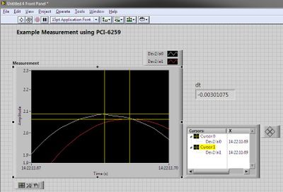
Bad drift with USB-6259 devices and acquisition of data PCI-6259
We have both a USB-6259 and PCI-6259 installed on a single computer, linked to a SBC-68, with Matlab and Toolbox of data Acquisiution.
For the purposes of test base, I wrote a script that generates a sinusoidal signal output based MATLAB, for a single DAC output. I wired this single DAC output to two channels of ADC of entry. For each sample output DAC, the script also takes a sample entry of ADC on each channel.
--> Ideally, if everything works correctly, after you run the script, I see two channels of input ADC vector. Tracing of each channel should give me a nice sine wave in Matlab.
--> When I made trace data, here's what I get (see attachment).
-->, I looked at the DAC output with an oscilloscope, and the DC offset is very close to 0 (this indicates to me that the part of output DAC works very well).
Why is there this negative DC drift on two entries?
Forgive my lack of knowledge - I know the difference between the DIFF and CSR connections, but I don't know where is the 'setting' for DIFF/CSR (what is a button/switch on the USB-6259 case? Is it a software control in the code?)
-
Create two independent signals and a pulse train with NI USB-6259
Hi all
I'm new to the forum, I searched but I've found no info about it.
I have recently set up a vi that is able to generate from an NI USB-6259 case two different signals in frequency, amplitude and phase (see attachment).
To do this with each cycle of the memory buffer size is changed accordingly for frequencies in order to see a whole number of periods and, thus, having not leak in the generation (or breaks).
Now, I would like to generate a pulse train at a frequency that is an integer multiple of the frequency of the input signal (not the 50 Hz one).
The resulting frequency of the pulse train could be changed on the fly (or at least be updated at each new round of vi).
I'm stuck because I have already said that two analog output channels and I want the pulse train so that a digital camera for my Board (channel PFI) output, you have any ideas?
Thank you very much
Alberto
PS. the vi is "program generazione.vi" but you must first install "signal.vi production".
Hello
It is a simple .vi which generates a configurable, buffered pulse train dynamically. I also want to let you know that with this type of advice (DAQ), it is impossible to update the output in real time. You must be careful because the time between you use "DAQmx Write" and the output effective physical change not IS NOT FIXED.Kind regards
Matteo
-
NI USB - 6259 BNC DAQ: analog input signal cross on the question
Hello
I use the NI USB-6259 BNC DAQ unit to acquire a four-channel analog signal, and I'm having a problem with a signal that affect others. The circuit, I am running is:
I have a wire connected to a battery (two AA batteries at ~1.5V), which then feeds the signal cable to a BNC cable, which feeds an analog BNC of data acquisition channel. The field of NBC feeds to another wire, which is attached to a conductive plate. The idea is this: when I touch the wire connected to the battery for the metal plate, I complete the circuit and thus get a binary not anything at all about 3V. When I tested with an osciloscope using two channels (each earth connection to the metal plate) I get independent steps whenever I touch any of the sons of the respective batteries to the metal plate (i.e. it works as expected). However, when I use it with data acquisition, whenever I touch a wire, I get a response in all other channels (3 others), even if their respective sons does not touch the metal plate.
No one knows why this happens, and how I might be able to stop this 'cross-talk '?
Thank you
Veritas
I see, and you're right. This request will have trouble with crosstalk. Luckily the ground channel thing should help you.
Configure your DAQ to collect twice as many channels as you need. Connect your wires in the odd channels and short circuit (ground) the entries of those even.
Now when you scan the channels it will always technically crosstalk, but it will come from a channel to the ground so that there will be nothing to interfere with your measurements.
At least that's the theory.

-
I have a VB6 program with code that correctly reads the analog inputs of a NOR-USB-6008.
I tried to re - use the code in a module of extensometer OR-USB-9237, but at the stage of DAQmxCreateAIVoltageChan, I get the following error:
"Measurements: physical channel selected does not support the type of measure required by the virtual channel you create."
Create a channel to a type of measure that is supported by the physical channel, or select a physical channel that supports the type of measure. »
Should I call one function other than DAQmxCreateAIVoltageChan?
If so, what is it, or where can I find the reference for these functions?
Or - if it of the right function, should I pass different arguments? Currently, I'll call you:
DAQmxErrChk DAQmxCreateAIVoltageChan(taskHandle, "Dev1/ai1", "", DAQmx_Val_Cfg_Default,-10, 10, DAQmx_Val_VoltageUnits1_Volts, "")
Thanks in advance for your help
-Alas
I thought she 372251a. PDF
Firstly, the correct function is DAQmxCreateAIVoltageChanWithExcit
Second, you can't just ask for a sample single channel - ask for 2 samples instead.
-Alas
-
Hi all
I have to admit that I am inexperienced with DAQ cards (just do simple things in the past). We just receive the NI USB-6259. The plan is to use it for many tasks. One of them is a digital signal to measure at the maximum rate. So far, I have tried ti create a task in MAX - what I've managed to achieve was to measure samples of 500-700 to 1 Mhz using N samples measurment. In order to have 1 Mhz sampling rates, I use an external clock PFI12 (output meter 0 - I put the counter to generate 20 Mhz Signal - 50ns/50ns time Time High/Low).
The thing is - it possible to obtain samples is acquired at 1 MHz with continuous mode? When I try with my current settings I get overrun error - I have tried task ru round trip - first clock generator started, then input digital. and the other way entry digital, first of all - so I guess that this overrun is not due to misuse.
In the documentation it says:
If the DAQ device receives a DI Sample Clock when the FIFO is full,
it reports an overflow error to the host software.
Is there another way to receive digital signals, where a picture lasts about 6 ms and consists of 8-bit?
-
Getting started with the NI USB-6259 housing
Hello, I'm quite new product OR. I try to use NI USB-6259 device for testing. I would like to write my application in pure C++ (Visual Studio 2005) but have not obtained from Measurement Studio for VS2005. I know it's possible to develop a full functional application for driver DAQmx without MS. I read some articles in the KB, but everywhere there is no specific information how start to develop. The paths on sites where there is default examples are not valid on my box. I have the driver NOR-DAQmx 8.7.1. Thanks in advanse.
Thanks for the help!
I finally found the examples using the C sources and it let me check if it is possible to develop an environment of use NI USB-6259. Now I'm thinking of creating access for this device, but I will ask on in a new thread.
Thanks again,
Dariusz Boczkowski
-
Using ChangeDetectionEvent with the NI USB-6259 housing
Hello
I am very new to labview and LabWindows, so maybe it's very trivial to solve.
I would like to perform an action (change some elements of the user interface) whenever I get a rising edge of a TTL signal.
I hoped to achieve by following the example of ReadDigChan-ChangeDetectionEvent, and by defining a DAQmxRegisterSignalEvent() front on one of the digital input lines, but I can't even use the example for my
USB-6259 (BNC).
When I try to perform detection of changes on the lines from the port 1 and 2 I get
Modalities indicated do not support change detection. Select the lines that support the detection of changes. Device: Dev1 physical Channel: port1/$line0 the task name: _unnamedTask<0> Code of State :-201020
I missunderstand something? Should the digital in ports on the detection of change of 6259 support?
When you try the same thing with port0 the application hangs for a long time and threw just a message saying that
DAQmxReadDigitalLines() timedout.
I hope this is enough information to answer the question. If not, what else do you need?
Thank you
Manual
Hello
It seems that the USB-6259 does not support the detection of changes.
Link:
In NOR-DAQmx digital change detection
-
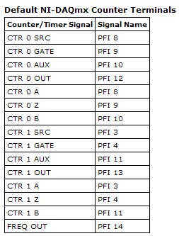
How to connect USB 6259 so that I can generate trains of pulses of a meter
Hello
We just bought NI USB-6259 BNC. We used to use BNC-2110, which integrates the connectors BNC for trigger and the meter so that we can send trains of pulses through it to our electric Stimulator.
However, I find no terminal BNC for the output of the meter on the new device. Could someone teach me how do?
Thank you
Jay
Hi, Jay.
Big question. The screenshot below will give you the Signal of Counter/Timer associated with its respective PFI line:
This table is located in the NOR-DAQmx help (using terminals of NOR-DAQmx devices"OR USB - 6259 BNC).
To access these lines PFI one of the BNC (User 1 and User 2) user-defined, the line due to PFI line of the user desired. For example, if I wanted to access counter 0 Out of 1 BNC user, I would wire pin 1 USER on pin 12 of PFI. Manual specifications USB-6259 BNC does not give a good description of how to access the user 1 and user 2 BNC, so I refer to page 9 of the Manual of the BNC-2110. It's the same idea, just different pinout.
Let me know if you need more information. I hope that you are having an amazing day!
-
Best way to generate the software clock for USB-6501 of Measurement Studio for c# VS2008
Hi all
I wonder if there is a better way to generate a clock software for USB-6501 of Measurement Studio for VS2008 in C Sharp?
I have developed a clock using C Sharp "Thread.Sleep (msecPauseTime)"; and statements to switch digital output high and low. There are a few things I noticed in creating a software clock in this way:
- The smallest delay by the Thread.Sleep command time is 1 millisecond (which means higher clock period is 2 msec-500 Hz, not holding not ball account no. 2 below).
- Sometimes the delay I see on an oscilloscope is considerably longer than the delay that I specified in the sleep command.
In my application, I create signals (a clock, a latch enable and data series) to control what an attenuator step through the USB-6501 RF connected to a USB 2.0 on my computer. This particular step RF attenuator can accept clocks with frequencies up to 10 MHz, so I would like to generate a software clock (without having to connect to an external clock to a line of input on the USB-6501) which is closest to this maximum frequency, and I think that the USB2.0 line could handle clock speeds over 500 Hz. Also, I would like to know why the delays that I see on the scope are sometimes longer than the time specified by the Thread.Sleep command. Is it caused by the suspension of the execution of my program processor for something else, as I suspect? Of course, this isn't a big deal, because it does not affect the time as my serial data and pieces change compared to my clock. However, I would like to know why it does this.
I appreciate your help.
Thank you
Jonathan Becker
Doctoral research engineer
Carnegie Mellon Silicon Valley
Jonathan,
Since the USB-6501 DIO is software programmed, you are at the mercy of the planning of the operating system and won't be able to work reliably with an external clock in the software.
You can try to set the priority of your thread 'generation of clock' to improve performance, however, because Windows is not a deterministic operating system, there are still no guarantees. Operating systems are not required to honor the priority of threads. You can find examples and information on the definition of the priorities of the threads in c# here:
http://msdn.Microsoft.com/en-us/library/system.Threading.thread.priority.aspx
Kind regards
-
Installation of the enclosure OR USB - 6259 Visual C++ Runtime Library Runtime Error
Hello
I am trying to install the NI USB-6259 DAQ card but I get a runtime error that says
Microsoft Visual C++ Runtime Library
Runtime error!
Program E:\setup.exe
This application has requested the execution to terminate in an unusual way.
For more information, contact the application support team.
I also installed LabView 7.1 but I still keep getting the same message. Any help please?
Thank you
Re-installation of Windows has not solved the problem.
The resolve this problem change the regional and Language Options of the control panel settings to the United Kingdom. That solved my problem.
Thank you
Steve
-
I work in can bus monitoring and I have a box NI USB-6259. is it possible to read data with NI USB-6259 CanBus?
Thank you very much..
Maybe you are looking for
-
I can go anywhere security iPhone easily! What is that? Contact me to say to solve than the Apple.
-
Z230 Tour: my desktop computer HP he TPM 1.2 support?
My company wants me to encrypt hard drives on all desktop computers. All are running Windows 10 Pro (x 64). When I try to enable Bitlocker encrypt the drive it says that I don't have a TPM 1.2 module. My questions: 1. my turn Z230 there a TPM chip on
-
Hi all, anyone know when ICS update will be available in India? Please update...
-
Create a new restore point shortcut
Would like to know where to find the way to have a Windows 7 desktop shortcut to create a new restore point. Thank you!
-
BT 3 business center and trying to network my hp laserjet p2055dn to this problem.
I have a new BT Hub 3 business and I'm trying my HP Laserjet P2055dn printer to the hub with an Ethernet network cable. The address of the printer - 192.168.2.2 IPv4 is not compatible. I said that I have to change the IP address of the printer, but I