phase shifted PWM with Ni 9401 and Crio
Hello
Do you have an idea of pwm shifted 180 degrees?
(duty cycle frequency and variable difficulty)
I tried a design, but it seems in the graphics design works on the realtime.vi but it does not work with the fpga.
Graphic output pwm FPGA are distinguished by the real time as you can see in the pictures.
On the other hand, VI Fpga produce two pwm, as seen in the oscilloscope when the fpga VI runs.
However, there is no phase shift between the PWM waves.
It is a part of my thesis, but I'm stuck in this problem, so I need assistance on your part.
Thank you.
Best regards;
My hardware:
cRIO-9024 and cRIO-9118 chassis
NOR-9223, 9263 - nor, nor-9401, or-9474
two nor-9225 and nor-9227
Hi Maurice
Thank you for your help.
Yes I want to that they will be moved with the right variable and 10 kHz. I put 49% maximum duty.
I put the output into the same output block.
Square wave generator does not accept 'loop' while.
I have attached a simple FPGA project file. Could you please tell me what is my fault?
The resulting Pwm frequency is 10 kHz, the only problem is always the shifters.
So, I always need assistance.
Tags: NI Hardware
Similar Questions
-
Meter with two adjustable phase shift
Hello
In this experimental device, I have a print head a TTL pulse-controlled piezoelectric ink jet delivering uniform droplets on a surface. I use the "time" version of the counter output vi (high-/ low-time) because it allows me to very easily change the characteristics of the droplets. I use a strobe approach for imaging the droplets as they are ejected. Basically, a strobe LED light is pulsed at a frequency that exactly matches that of the inkjet printhead. A CCD camera is used in order to imager droplets, who seem "frozen" on the screen due to the stroboscopic effect. Strobe LED is triggered by a train of pulses TTL (two pulse trains come from exits of meter on my USB-6353 X Series DAQ board).
Of course, I could trigger both the inkjet Printhead and the strobe light with the same output of counter, which would ensure that their frequencies match. But it's really nice to have a 'strobe delay' that allows adjustment of the phase shift between the strobe triggers and printhead. The hardware supplied with the print head has this feature of strobe delay as an external button. It is useful, because you can basically lead through time by turning the button and view the formation of droplets when it leaves the end of the nozzle.
I have a vi that may trigger sometimes the printhead and the flash, but I can't understand how to adjust a phase shift between the two, while the program is running. It should be possible, but I can't get it. I would really appreciate help with this. Attached is the draft code and a diagram which may help to explain what I want to do
Thank you very much
-Matt
No - forget the INITIAL DELAY. It's only for the (first) INITIAL pulse.
You already want to adjust the time / low-time already, no?
So having a new control called PHASE SHIFT, from scratch.
Have a variable called OFFSET PHASE CURRENT, from scratch.
When the PHASE SHIFT is modified (by the user), understand the difference between where he wants to be and where you are (control - PHASE CURRENT OFFSET) and add a lot of time the low TIMES, but only during a cycle. Basically you're stretching of a cycle. Store the new value in the course of PHASE SHIFT variable for next time.
-
Hello everyone,
already, I asked once about the creation of PWM with hardware. And I was pleased with the response. But now I found 94xx Series-USB OR hardware. Here are the materials of high-voltage-Digital i/o. If any of you have already met with this one, would like to hear your conclusion about them. Would also appreciate if you could answer my question:
Is it possible to create a PWM Signal with NOR-USB 94xx?Thank you
Grigory
Grekov wrote:
I'd be more interested in the USB Module NI 9472 USB connection. Because it's the only one that would match my request.
What is your application?
Why don't choose you something in this list.
If your condition is out to say 24 v PWM signal... you can also plan to use a custom circuit intermediate, not only to scale the output signal of the device (at 24 v) but also the reader following circuit.
-
Hello world!
First of all, I use a USRP as a transmitter to emit a sine wave (the signal is exp(j2*pi*f*t)), and then I use the external clock to synchronize the two USRPs (Ref as PPS in are connected to the clock) as receivers. Receivers are in sync, and they are at the same distance from the transmitter, I thought that the signal they receive should have a nearly the same phase. However, in practice, the phase shift is big enough, and this problem really confuses me.
It's the received signals of 2 receivers.
Yes. What you observe is expected.
Near the bottof of this document read the area 'alignment Phase vs Phase coherence '.
http://www.NI.com/white-paper/14311/en/
And also, for the alignment phase, see the following 'Angle of arrival detection with NI USRP '.
https://decibel.NI.com/content/docs/doc-25716
Erik
-
Align the two signals and measure the Phase Shift
Hello
I do an experiment in which I use the NI USB-6221 DAQ card. The jury is able to make 250 k samples/second. I want to measure two voltages in a circuit and find the phase shift between them at frequencies between 1 and 10000. First I ouputted a wave sinusoidal frequency variable through the Commission and applied to a test circuit. Then I used the Board to measure the two tensions consecutively (thus reducing the maximum sampling frequency at 125 k). I used the signals align VI and measured the two phases and then calculates the phase shift (VI attached in Phase 1). It worked well for the test circuit I built in which the phase shift went way logarithmique.20 degrees ~84.5 degrees and then stabilized. At frequencies above 5 000 Hz phase shift must have remained constant, but it varies more or less 1 degree. When the phase shift is 84.5 degrees, present a degree of variability is not particularly explicit. When I asked my program on the circuit that I really wanted to measure, the phase shift went from-. 5 degrees up to about 1.2 degrees. The change in the values of phase shift at high frequencies (> 3000) was environ.2 degrees. Given the small phase shift, this variation is unacceptable. Now I tried to use a sequence to each blood individually (increase the maximum sampling frequency to 250 k) and then align the two signals and measure the phase of each shift. When I use align it and re - sample Express VI to realign the two signals, I get the message "error 20333 analysis: cannot align two waveforms with dt even if their samples are not clocked in phase." Is it possible to align two signals I describe here? I enclose the new VI as Phase 2
Matthew,
I think I have an idea for at least part of the problem.
I took your program data and deleted stuff DAQ. I have converted the Signal on the chart control and looked then what was going on with the signal analysis.
The output of the Waveforms.vi line has two waveforms, like the entry. However, arrays of Y in the two waveforms are empty! It does not generate an error. After some head scratching, reading the help files and try things out, that's what I think is happening: the time t0 two input signals are 1,031 seconds apart. Since the wavefoms contains 1,000 seconds of data, there is no overlap and may not align them.
I changed the t0 on two waveforms are the same, and it lines up. The number of items in the tables is reduced by one. Then I increased the t0 of 0.1 seconds on the first element. The output had both greater than the entry by dt t0 t0 and the size of the arrays was 224998. Reversing the t0 two elements shifts the phase in the opposite direction.
What that tells me, is that you can not reliably align two waveforms which do not overlap.
I suggest that you go to 2-channel data acquisition and that it accept the reduced sample rate. You won't get the resolution you want, but you should be able to tell if something important happens.
You may be able to improve the equivalent resolution by taking multiple steps with a slight phase shift. This is similar to the way that old oscilloscopes of sampling (analog) worked. Take a series of measures with the signal you are currently using. The make enough average to minimize changes due to noise. Then pass the phase of the signal of excitement to an amount that is smaller than the resolution of phase of sampling rate and repeat the measurements. Recall that I calculated that for a 5 kHz signal sampled at 125kHz, you get a sample every 14.4 degrees. If shift you the phase of 1 degree (to the point/mathematical simulation), you get a different set of samples for excitement. They are always separated by 14.4 degrees. Take another series of measures. Transfer phase another degree and repeat. As long as your sampling clocks are stable enough so that frequency does not drift significantly (and it shouldn't with your equipment), you should be able to get near resolution of what you need. The trade-off is that you need to perform more measurements and may need to keep track of the phase shifts between the various measures.
Lynn
-
With the help of cRIO-9073 with 9403 module and Ping sensor
I try to have a Ping of Parallax))) to work with my cRIO ultrasonic sensor. I have connected it to an e/s digital 9403 module and uses the PulseGen, SW.vi example. I plugged in and configured the 0 for an output pin have significance attatched on the output pin to monitor output. When I put the pulse width to be something less than 10 ms long and I try it is not always release trigger and when that happens it's always long to 10ms. is there a way to reduce this sort I get a pulse of what 5?
Hi digilogik,
You can post how you have changed the code, so we have a better understanding of what to expect. Brief looking at the example code I couldn't guess why a long 10 ms pulse is the only thing you see if what you did was replace the power indicator 0 with IO nodes.
However, if your end goal is to get a pulse of 5 usec, then the NI 9403 module will not respond to your needs as the updated module is 7usec max. You would be able to do what you need with a NI 9401 module, with the draw back you go to 32 channels up to 8 with the 9401 vs the 9403.
Bassett Hound
-
How can I do a phase shift and amplitude change on wavefile which is read in
Hello all
I have a wavefile which has two channels, left and right, I would make a phase
SHIFT and amplitude change on one of the channels. Can I split each channel
in the tables, but I don't know how to do a phase shift and amplitude change on the
Table to get the new signal.
TIA sal22
Hi Sal,
Here's a way to implement the phase change:
In regards to the change of amplitude, you could just multiply all of the table with the desired value.
-
With the help of a Butterworth filter without phase shift
Hello
I found this reference to the use of a Butterworth filter without phase shift http://zone.ni.com/devzone/cda/epd/p/id/2775 but I can't open the sample with LabView 2011. Can anyone help? The referenced file is attached.
Is there another or the best way to do this?
Thank you
Attached is a version saved in LV2009.
In such cases, you can validate the vi to the discussion of queries VI Upconvert.
Ben64
-
Phase shift a channel and display
Hello
I'm working on a project for which I have to display the I-Q constellation plot and normalize the data to fit a circle of unit RADIUS.
I'm able to do this, but the problem is sometimes the signal in one of the channels is very low and therefore, the plot moves close to the routes (Please find attached the file, this is the best position, if a channel has a weak signal, the movements from point to one of the axes). When this happens, I want to add a phase shift of the signal (45 degrees and multiples of it) to bring to the back for the best position. I tried to use the extracted tone vi phase go, add 45 degrees, but how to rebuild the spirit of the new signal phase?
Can someone help me please?
Thank you very much
Despres
-
9225 and 9227 Module Constant phase shift (Drift)
Hello
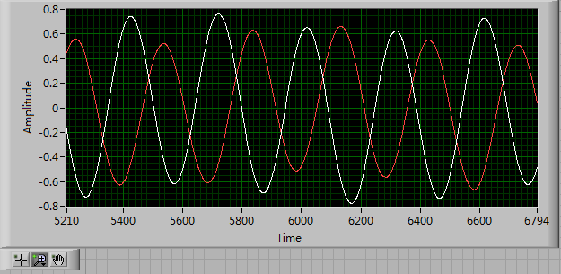
I wrote a large VI and the am acquisition voltage and current with the 9225 and 9227. The phase of the voltage and current constantly derivatives. Its not just for phase a bit for all of the portion; the phase constantly cycles from 0 to 360 degrees. I have an excel file with locations showing what I mean. Series 1 = voltage 2 = current
I wrote a small VI to do the same thing with nothing extra. I have not yet add the data record. I just use a graph to plot the voltage and phase. The voltage and current were still off!
What do you think. Timers are bad on the modules? Slow computer? DAQ assistants are not good? IM using the internal timers in the modules.
Synronizing at the beginning does not help because the signals would still go out of phase when even later. The load is a piezoelectric tube.
I'm using Labview 2011 and NEITHER cDAQ-9178:
9225 3CH 300 Vrms 24 BIT simultaneous AIN
9227 4CH 24-BIT simultaneous AIN 5ArmsSee you soon
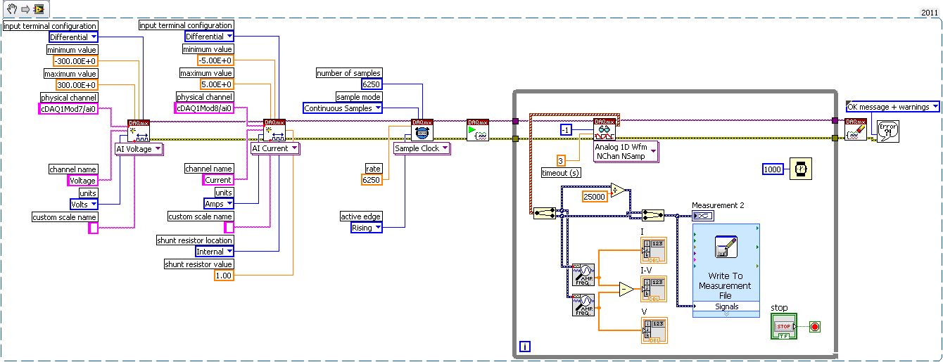
I forgot to change to continuous. I do usually. The major difficulty that I did was remove the trigger "Start Digital Edge" completely. The trigger wasn't working properly with what I put it in, "PFI0"... Once I took it out, I got a sample invaded. I played with the numbers of the sample for the clock sampling and playback. I don't know why to use 25000 everywhere has not worked. But when I dropped the numbers to 6250 or something of this magnitude, the VI finally worked.
The VI works with or without the clock I specified (Mod7/AI/sampleclock), which is great news! Thanks for this tip!
The current and voltage are finally in sync. They will never out of sync! Finally I can calculate the POWER!
This digital trigger was the worst headache... Thanks for the tips!
I write the VI and the code snippet to my completed solution.
-
make a request using pt100 with cseries 9219 module and crio 9014
How can I connect my module pt100 with series c 9219 module and crio-9014
The description is in table 1, but they are signals and lines of the TEDS data COM. More information on TEDS found on page 11 of the manual and a page of links to http://www.ni.com/white-paper/3468/en.
-
How to use NI 9264 and NI 9205 with NI PXI-7813R and cRIO-9151
Hello world
I am currently working on an application in time real NI PXI-7813R (map FPGA) and NI PXI-8184 (on-board controller). They are all in an NI PXI-1031 chassis.
I need to generate/receive analog signals.
I already managed to use the SCB-68 with my NI PXI-7813R (FPGA card) to process digital signals. (Slot 0)
Connector 1 and 3 of my FPGA I have respectively cRIO-9151 with NI 9264 for analog and cRIO-9151 output with NI 9205 for the analog input.
- with NI 9264, I have on every 16 outputs-10, 5V (!) Isn't it supposed to be between-10 and 10V?), whether or not the vi runs. (But not when my PXI turned...)
- with the NI 9205 module, I always get-32767 when the VI is running, regardless of pressure I apply. (I tested AI0 and AL10)
Maybe is my hardware not configured properly? I did the configuration automatically, when I started the project, Labview detected the devices connected.
Unfortunately, MAX does not seem to be useful because inputs and outputs are on the FPGA...
Any idea?
Thank you
PS: VI on the FPGA is really basic, only read/write controls.
Hello
Back with the solution...
My modules came! Each of them has been plugged in the wrong cRIO-9151.
This must occur after the first configuration.
I noticed when I right click on my fpga device > RIO Device Setup. I wanted to check the devices again, but crashed for Labview.
I could also have seen 'Connector [number]' (automatically added by Labview) and the removal of material number (9205 or 9264) in the project and check if it really was what I had.
Hope that my mistake will help someone in the future...
-
Encoder interfaced with NOR-9401
I bought a coder who has open collector and resistance to pull-up 3.3 kohm (TTL) logic output.
The encoder comes with four sons: power + 5V, GND, channel A and channel B. channel A and B are logic output.
Channel A and B are connected to the OID of NOR-9401 which is mounted on the cRIO.
A standard VI for encoder counting is used and compiled under the FPGA environment.
During the measurement, I have observed that there are number of significant loss in both directions encoder.
I don't think that there is a problem with VI like I used it several times on the encoders with output RS422.
Is there a problem with my current encoder with respect to its electrical interface with NOR-9401?
Thank you.
I don't think that there is a problem with pull-up resistance. Even if the digital IO ports have their own resistance to pull-up (usually of the order of 4.7kOhm - should be included in the manual), the power to be handled by the circuit of encoder output transistor is about 2mA. -Check your configuration for a correct connection GND. You must connect the encoder directly power GND to DGND to the printed circuit board Terminal.
-
variable phase shift between two analog output signals
Hey! I would drive two different piezo elements with an sine - / square signals and have a phase shifted output signals. After some trail and error, I was able to get a second analog output on my card PCI-6221 (using LabView 8.2) also allowed me to have different amplitudes for both signals. However, I could not output signal having a frequency different and most importantly to my request to have one of the signals variably shifted phase.
Thanks for the very useful suggestion. I have attached the file .vi installation I've run so far.
Hello!
A way to generate waveforms is using the analog waveform Toolbox. I created an example VI that is attached and that shows you a way to use the base generating function VI. I saved for LabVIEW 8.2.
I hope this helps!
-
Transformed Hilbert phase shift of 90 degrees
I am usig transformed from Hilbert to provide me with a shift of the phase of the signal of a UHF radar unit.
When I try to get the soft wave phase I get nothing. But when I replicate the output of the HIlbert and do a sinus I have the orginal without the phase shift wave.
When I use a simulated sine wave and use the transformed Hilbert for her, I get a wave that is shifted by 90 degrees.
So can you please help me with some splitters using Hilbert.
There the best solutions for the phase shift?
If you get a point at a time, use the version ptbypt as already mentioned. It includes a configurable size buffer.

Maybe you are looking for
-
Office Jet Pro 8500: HP Solution Center fails to launch after W10 KB3132372 is installed.
30/12/15 HP Solution Center does not launch after installing W10 KB3132372. Patch to correct vulnerabilities in Adobe Flash Player in Internet Explorer and Microsoft Edge: 29 December 2015 I removed this update and the solution Center launches succes
-
OfficeJet Pro 8500: HP Officejet Pro 8500 driver for windows 8.1
I have a "startup CD-ROM' Officejet Pro 8500 A909, Windows 7, Version 13.0.0,, which does not recognize my Windows 8.1. Is there any possibility to get a driver for 8.1, even if there is a fee for this? I need this printer, but it is useless if I can
-
Establishment of recovery media
I am trying to create recovery media for a Compaq CQ58-341SA (E3D22EA) which belongs to my old neighbours. Whenever the process reached the stage of burning, the following message appears: "we live errors in the creation of recovery media. Please try
-
My contact list blackBerry smartphones
I cannot edit any contact and also impossible to add new contact. What can I do?
-
Hey there!I'm doing a text like predefined shape to creat my poster effect but I don't get a predefined brush option is selected, check the image and tell the solution. . !