Meter with two adjustable phase shift
Hello
In this experimental device, I have a print head a TTL pulse-controlled piezoelectric ink jet delivering uniform droplets on a surface. I use the "time" version of the counter output vi (high-/ low-time) because it allows me to very easily change the characteristics of the droplets. I use a strobe approach for imaging the droplets as they are ejected. Basically, a strobe LED light is pulsed at a frequency that exactly matches that of the inkjet printhead. A CCD camera is used in order to imager droplets, who seem "frozen" on the screen due to the stroboscopic effect. Strobe LED is triggered by a train of pulses TTL (two pulse trains come from exits of meter on my USB-6353 X Series DAQ board).
Of course, I could trigger both the inkjet Printhead and the strobe light with the same output of counter, which would ensure that their frequencies match. But it's really nice to have a 'strobe delay' that allows adjustment of the phase shift between the strobe triggers and printhead. The hardware supplied with the print head has this feature of strobe delay as an external button. It is useful, because you can basically lead through time by turning the button and view the formation of droplets when it leaves the end of the nozzle.
I have a vi that may trigger sometimes the printhead and the flash, but I can't understand how to adjust a phase shift between the two, while the program is running. It should be possible, but I can't get it. I would really appreciate help with this. Attached is the draft code and a diagram which may help to explain what I want to do
Thank you very much
-Matt
No - forget the INITIAL DELAY. It's only for the (first) INITIAL pulse.
You already want to adjust the time / low-time already, no?
So having a new control called PHASE SHIFT, from scratch.
Have a variable called OFFSET PHASE CURRENT, from scratch.
When the PHASE SHIFT is modified (by the user), understand the difference between where he wants to be and where you are (control - PHASE CURRENT OFFSET) and add a lot of time the low TIMES, but only during a cycle. Basically you're stretching of a cycle. Store the new value in the course of PHASE SHIFT variable for next time.
Tags: NI Software
Similar Questions
-
Align the two signals and measure the Phase Shift
Hello
I do an experiment in which I use the NI USB-6221 DAQ card. The jury is able to make 250 k samples/second. I want to measure two voltages in a circuit and find the phase shift between them at frequencies between 1 and 10000. First I ouputted a wave sinusoidal frequency variable through the Commission and applied to a test circuit. Then I used the Board to measure the two tensions consecutively (thus reducing the maximum sampling frequency at 125 k). I used the signals align VI and measured the two phases and then calculates the phase shift (VI attached in Phase 1). It worked well for the test circuit I built in which the phase shift went way logarithmique.20 degrees ~84.5 degrees and then stabilized. At frequencies above 5 000 Hz phase shift must have remained constant, but it varies more or less 1 degree. When the phase shift is 84.5 degrees, present a degree of variability is not particularly explicit. When I asked my program on the circuit that I really wanted to measure, the phase shift went from-. 5 degrees up to about 1.2 degrees. The change in the values of phase shift at high frequencies (> 3000) was environ.2 degrees. Given the small phase shift, this variation is unacceptable. Now I tried to use a sequence to each blood individually (increase the maximum sampling frequency to 250 k) and then align the two signals and measure the phase of each shift. When I use align it and re - sample Express VI to realign the two signals, I get the message "error 20333 analysis: cannot align two waveforms with dt even if their samples are not clocked in phase." Is it possible to align two signals I describe here? I enclose the new VI as Phase 2
Matthew,
I think I have an idea for at least part of the problem.
I took your program data and deleted stuff DAQ. I have converted the Signal on the chart control and looked then what was going on with the signal analysis.
The output of the Waveforms.vi line has two waveforms, like the entry. However, arrays of Y in the two waveforms are empty! It does not generate an error. After some head scratching, reading the help files and try things out, that's what I think is happening: the time t0 two input signals are 1,031 seconds apart. Since the wavefoms contains 1,000 seconds of data, there is no overlap and may not align them.
I changed the t0 on two waveforms are the same, and it lines up. The number of items in the tables is reduced by one. Then I increased the t0 of 0.1 seconds on the first element. The output had both greater than the entry by dt t0 t0 and the size of the arrays was 224998. Reversing the t0 two elements shifts the phase in the opposite direction.
What that tells me, is that you can not reliably align two waveforms which do not overlap.
I suggest that you go to 2-channel data acquisition and that it accept the reduced sample rate. You won't get the resolution you want, but you should be able to tell if something important happens.
You may be able to improve the equivalent resolution by taking multiple steps with a slight phase shift. This is similar to the way that old oscilloscopes of sampling (analog) worked. Take a series of measures with the signal you are currently using. The make enough average to minimize changes due to noise. Then pass the phase of the signal of excitement to an amount that is smaller than the resolution of phase of sampling rate and repeat the measurements. Recall that I calculated that for a 5 kHz signal sampled at 125kHz, you get a sample every 14.4 degrees. If shift you the phase of 1 degree (to the point/mathematical simulation), you get a different set of samples for excitement. They are always separated by 14.4 degrees. Take another series of measures. Transfer phase another degree and repeat. As long as your sampling clocks are stable enough so that frequency does not drift significantly (and it shouldn't with your equipment), you should be able to get near resolution of what you need. The trade-off is that you need to perform more measurements and may need to keep track of the phase shifts between the various measures.
Lynn
-
phase shifted PWM with Ni 9401 and Crio
Hello
Do you have an idea of pwm shifted 180 degrees?
(duty cycle frequency and variable difficulty)
I tried a design, but it seems in the graphics design works on the realtime.vi but it does not work with the fpga.
Graphic output pwm FPGA are distinguished by the real time as you can see in the pictures.
On the other hand, VI Fpga produce two pwm, as seen in the oscilloscope when the fpga VI runs.
However, there is no phase shift between the PWM waves.
It is a part of my thesis, but I'm stuck in this problem, so I need assistance on your part.Thank you.
Best regards;
My hardware:
cRIO-9024 and cRIO-9118 chassis
NOR-9223, 9263 - nor, nor-9401, or-9474
two nor-9225 and nor-9227
Hi Maurice
Thank you for your help.
Yes I want to that they will be moved with the right variable and 10 kHz. I put 49% maximum duty.
I put the output into the same output block.
Square wave generator does not accept 'loop' while.
I have attached a simple FPGA project file. Could you please tell me what is my fault?
The resulting Pwm frequency is 10 kHz, the only problem is always the shifters.
So, I always need assistance.
-
Hello world!
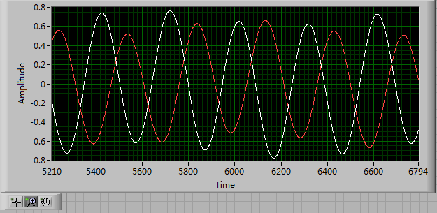
First of all, I use a USRP as a transmitter to emit a sine wave (the signal is exp(j2*pi*f*t)), and then I use the external clock to synchronize the two USRPs (Ref as PPS in are connected to the clock) as receivers. Receivers are in sync, and they are at the same distance from the transmitter, I thought that the signal they receive should have a nearly the same phase. However, in practice, the phase shift is big enough, and this problem really confuses me.
It's the received signals of 2 receivers.
Yes. What you observe is expected.
Near the bottof of this document read the area 'alignment Phase vs Phase coherence '.
http://www.NI.com/white-paper/14311/en/
And also, for the alignment phase, see the following 'Angle of arrival detection with NI USRP '.
https://decibel.NI.com/content/docs/doc-25716
Erik
-
variable phase shift between two analog output signals
Hey! I would drive two different piezo elements with an sine - / square signals and have a phase shifted output signals. After some trail and error, I was able to get a second analog output on my card PCI-6221 (using LabView 8.2) also allowed me to have different amplitudes for both signals. However, I could not output signal having a frequency different and most importantly to my request to have one of the signals variably shifted phase.
Thanks for the very useful suggestion. I have attached the file .vi installation I've run so far.
Hello!
A way to generate waveforms is using the analog waveform Toolbox. I created an example VI that is attached and that shows you a way to use the base generating function VI. I saved for LabVIEW 8.2.
I hope this helps!
-
With the help of a Butterworth filter without phase shift
Hello
I found this reference to the use of a Butterworth filter without phase shift http://zone.ni.com/devzone/cda/epd/p/id/2775 but I can't open the sample with LabView 2011. Can anyone help? The referenced file is attached.
Is there another or the best way to do this?
Thank you
Attached is a version saved in LV2009.
In such cases, you can validate the vi to the discussion of queries VI Upconvert.
Ben64
-
How to upgrade a shift with two independent loops while register?
Hello everyone, I have a panel with two clusters with indicators control... a left and a right. I have messages from serial port, and I'm currently updating the left and the right within their own while loops. I have a single variable, which must be updated based on updates on both sides. Basically, I need follow the last selection update on each side... If I had 1, 2 and 4 on the left side and 3 on the right side... I would need to follow 4 was the latest updated the register shift variable for uses more in my vi. Can someone give me an idea how to upgrade this a variable based on two while loops that run independently in the same sequence context? Thanks in advance, cayenne
Thank you both of you for the suggestion.
I managed to find a way to get the values that I needed without EI... but I read the link to the Nugget in their subject, and I can't expect a use for them in the future.
Cayenne
-
How can I do a phase shift and amplitude change on wavefile which is read in
Hello all
I have a wavefile which has two channels, left and right, I would make a phase
SHIFT and amplitude change on one of the channels. Can I split each channel
in the tables, but I don't know how to do a phase shift and amplitude change on the
Table to get the new signal.
TIA sal22
Hi Sal,
Here's a way to implement the phase change:
In regards to the change of amplitude, you could just multiply all of the table with the desired value.
-
I want to spend a lot of photos (they are in order) but and do not want to have to click to move each photo. I know there is a simple control function that allows to select groups of files with ' two'clicks ', as opposed to the selection of each file. Suggestions? I know it's apple 101, but I don't remember what order to press the button command, or shift, or other. Thank you
Select the first file, then hold down the SHIFT key, and then click the last file. Or, select any file in the folder and then press command + A
-
FGV with two types of variables
It goes something like this
I want the FGV having a cluster of two tables 1 d of double (which will be the variable of the FGV). and the data that I am 'Add' is a double issue / constant (whatever), it will be the additional variable.
the main idea is that I want to be able to choose to which one of the two i added the extra number and I think that it is quite easy to achieve with a simple Boolean control (reference) and the structure of the case, that's what I did.
the problem is that if I what that it either does not connect the FGV labview shift register does recognize as the FGV variable, that I have just described, and if I do, it's an extra entry which I don't want to use it later.
in theory, I can do my extra variable to be also a cluster with two tables 1 d of type double, however, given that my entry has a single issue, I do not know how to accomplish it.
Thanks in advance.
It would be good to know if something like this is even possible. (first option)
-
detection of peak with two thresholds
Dear colleagues!
Excuse me, but I need example or any help for the detection of peaks with two thresholds. Namely two adjustable thresholds with detector standard Ridge for the creation of a detection bandwidth or range.
Detector of crete have only one threshold of... But why only one...

-
Transformed Hilbert phase shift of 90 degrees
I am usig transformed from Hilbert to provide me with a shift of the phase of the signal of a UHF radar unit.
When I try to get the soft wave phase I get nothing. But when I replicate the output of the HIlbert and do a sinus I have the orginal without the phase shift wave.
When I use a simulated sine wave and use the transformed Hilbert for her, I get a wave that is shifted by 90 degrees.
So can you please help me with some splitters using Hilbert.
There the best solutions for the phase shift?
If you get a point at a time, use the version ptbypt as already mentioned. It includes a configurable size buffer.
-
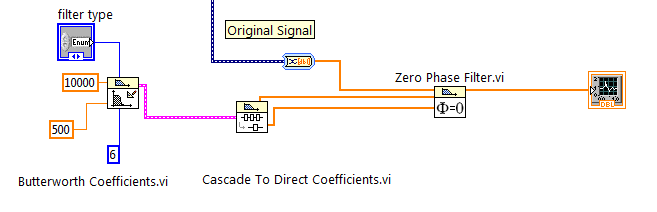
Butterworth filter without phase shift
Hello
I would like to design a 6 without a phase shift of order butterworth filter on my signal. A cutoff frequency of 500 Hz was chosen with a sampling rate of 10K Hz
Solved! Thank you ADE77
-
Phase shift USRP N210 WBX has not remained constant
Hello
Here's the anouced;
After setting the RF front end, each local oscillator can have a random phase offset by separators in the VCO/PLL channels. This shift will remain constant after initialization of the device and will remain constant until the device is closed or re-look.
However,.
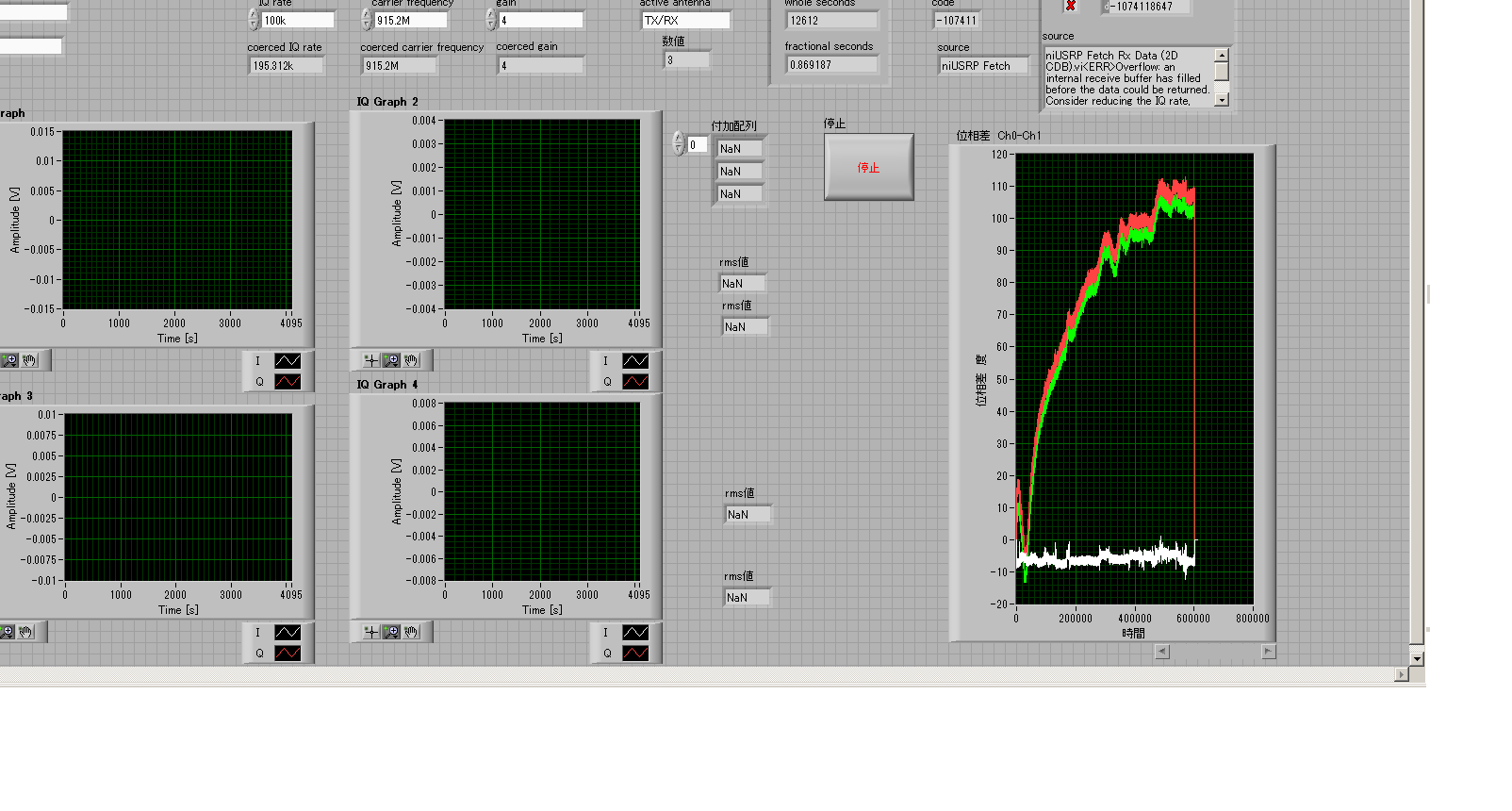
I found the phase shift has not remained constant for some USRP N210 with WBX in system of synchronized receivers USRP N2x0 20 minutes.
I'm currently building the measurement system of synchronized phase using USRP N200 x 2, x 2 OCTOCLOCK N210.
CH1 and ch2 is connected with the MIMO cable
Ch3 and ch4 is connected with the MIMO cable
CH2 and ch4 is connected OCTCLOCK wiith 10 MHz and PPS.
All entries were coupled to the SG not sincronized exit.
attached screenshot shows the results observed for 200 minutes. .
Right end indicates derivative of phase offset for 200 minutes; white line is ch2 - ch1, red line is ch3 - ch1, green line is ch1 - ch4.
It seems that each pair MIMO has kept the same phase offset but pairs diffreent MIMO.
Is - this results?
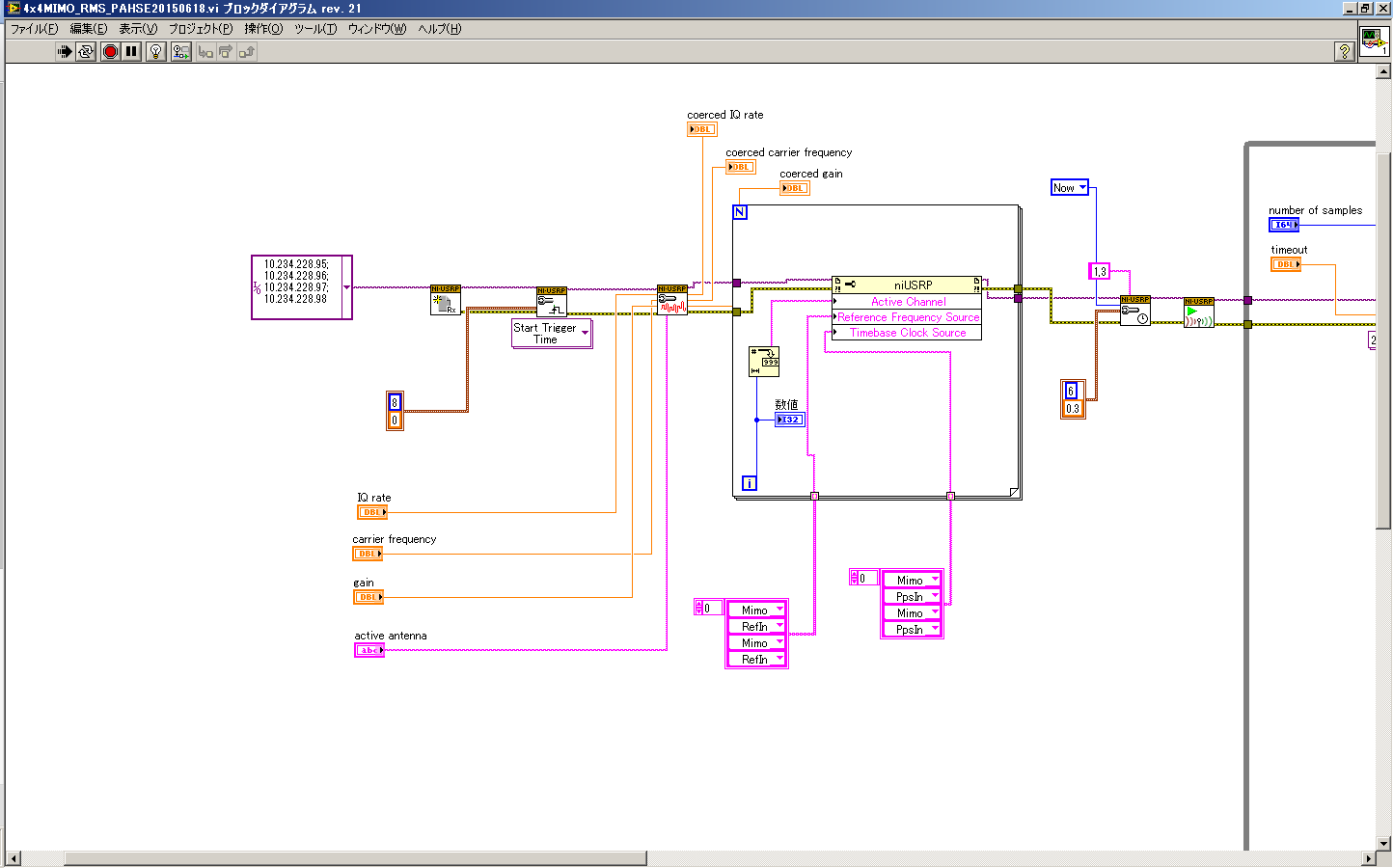
Here's the configulation in LabVIEW Block diagram.
I tried like and found my phase USPR N210 WBX offset remains constant.
My vi can be a bad thing.
Sorry for the bad because of my misunderstanding infromation display.
After fixing my mistakes of Vi, I'll show them.
-
bar graph with two scales of y
Hello
I have a graph with two scales different (one on the left side from 0 to 50, the other to the right of 0 to 1)
Now I want to draw horizontal lines limit. I do this with the programately adjustment sliders.
But I can only put the sliders that "belongs" to the first scale.
Is there a solution?
Thanks for any help
Yves
LV 8.6
Hi Yves,
You can assign each slider to a YScale. Simple right click on the cursor and choose the YScale. I think you can also do it programmatically.

Maybe you are looking for
-
Hello Why I can't boot from a USB? I'm looking to replace a failed hard drive in a Mac Mini 2010. I replaced the hard drive without difficulty. I have a USB flash drive from known good 10.10.5 with an Installer (tested) well known about it. I pre
-
I'm still all the original Microsoft disks that were used to install microsoft on my system...
-
my screen resolution won, t change. _
the only option is to 640 x 480
-
The list of unread on OS 6 message bar notification
Hi all You all know that the OS 6 comes with notification bar that if we get to the bottom of the bar, it will display the message unread recently. I just want to ask if there is any API / tutorial we use to list our message in the menu bar to the bo
-
BlackBerry 8820 smartphones cannot synchronize all of a sudden
My 8820 has been nicely synchronization then I tried some security settings, and now the Office Manager says 'Work' and does not synchronize more just. Help