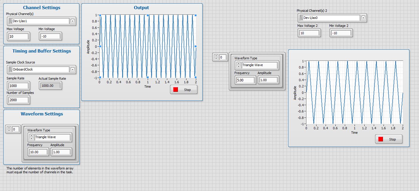
variable phase shift between two analog output signals
Hey! I would drive two different piezo elements with an sine - / square signals and have a phase shifted output signals. After some trail and error, I was able to get a second analog output on my card PCI-6221 (using LabView 8.2) also allowed me to have different amplitudes for both signals. However, I could not output signal having a frequency different and most importantly to my request to have one of the signals variably shifted phase.
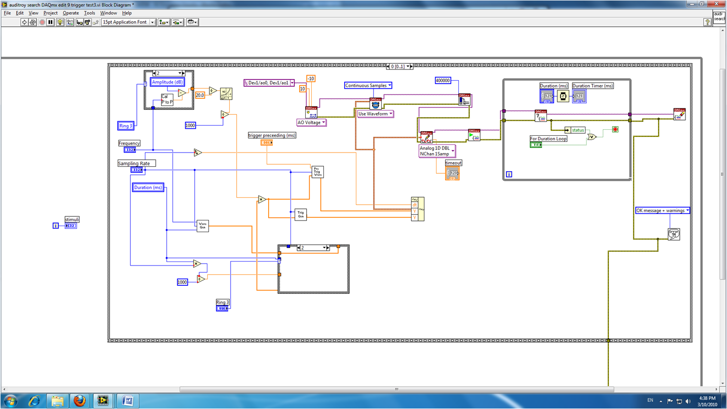
Thanks for the very useful suggestion. I have attached the file .vi installation I've run so far.
Hello!
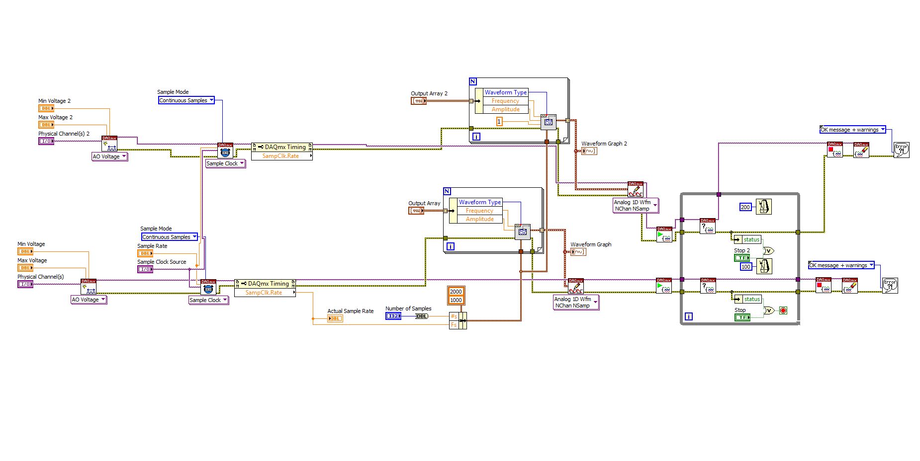
A way to generate waveforms is using the analog waveform Toolbox. I created an example VI that is attached and that shows you a way to use the base generating function VI. I saved for LabVIEW 8.2.
I hope this helps!
Tags: NI Software
Similar Questions
-
measurement of phase shift between two periodic signals acquired
Hello
I don't know how to explain my problem, but I'll give it my best shot. I'm two signals from sensors in tension. Two periodic signals have the same frequency, but a different amplitude. Normally they have a difference of phase of 0 or 180 degrees. The thing I have to let labview to check is if the signals are completely in phase or out of phase (180 degrees) completely. I am acquiring the wizard scene DAQ in a while loop. Does anyone have an idea how I can do this?
To summarize: are the two things I need to know
-l'amplitude (maybe just pick max max min distance)
-If both signals are moving in the same direction (when the two signals are in phase) or if they move in the opposite direction (counter phase) - the exact phase angle value is not so important
THX
Thanks for the reply. After a night to think about the problem, I came up with a home-made solution. I used the point by point max and min vi to calculate the distance from crest to crest of my signals. Then, I used the time derivative of point by point to calculate the variation of the signal of the two signals. If the signals are in phase (both are increasing or decreasing at the same time with the other), then the two derivatives have the same sign (accept on the summits, of which I have excluded from the comparison). If the signals are out of phase (when one increases, the other is decreases and vice versa) then the two derivatives are opposite in sign. According to this, I can get all information that I need. If anybody should know a better way to achieve the same result, please say, but to know that it seems to work.
-
I want to do simultaneous 180 continuous signal phase (square) to 2 analog outputs
Hello
I would like to use a meter to trigger (internally) 2 outputs analog, such as the continuous AC signal to each output is shifted 180 degrees.
I hoped to do with no external connection in addition to the ao0 and ao1 was to use a timer as a trigger counter and have a trigger analogOutput on the front and the other trigger on the falling edge to get the required result.
However, it doesn't matter how I get there. An absolute requirement is that two continuous AC signals are present to ao0 ao1 outputs and they are out of phase by 180 degrees and all trigger occurs on the PXI bus with no other connections external that is frequency of 25 Hz. My card is an SMU-6363.
I was hoping to get the hardware to do all the work of relaxation but if there is a trigger of software approach that would be
Thank you
That's what I ended up doing. microseconds is quite good enough.
-
Generating analog output signals 4 with different frequencies
Hi all
I was trying to say to generate 4 different signals at different frequencies
1. first waveform is a sine wave with 5000 Hz,
2. other with 8000Hz,
3. third, one is a square with 25 Hz waveform and
4. fourth one with triangular waveform 50 Hz
all waveforms must be generated simultanoeusly.
I tried to generate with the task unique analog output and sample clock (clock rate is 100000). Cross in scope that I see only 5000 and 8000 Hz we generated correctly and the rest two waveforms show the incorrect frequency.
I guess that's due to the frequency of high clock to sample for more low frequencies for ex 25 Hz and 50 Hz. If I reduce the clock rate to get the lower frequencies properly so I can't generate frequencies higher correctly. (there's a clsh between frequencies and the clock frequency)
Is it possible to use DAQ board master sample clock and its magnitude downward revision (everywhere where it is necessary for each waveform separately) to generate all the signals at different frequencies at the same time in a single task?
-
Hello
Currently, we have two signals which are physically and logically linked together on the same line of data acquisition. The first, 'I' and the second signal, 'Q', are both related to "Ai6" (PIN 23) and "Ai GND" (Earth). However, when we probe the two lines coming our function "signal split", I drove Q by about 0.5ms. My question is, if these two lines are actually bound together physically and logically, then why are they phase shifted if they are both the same channel? They should be exact matches. I thought that the phase delay inter-channel occurs only in what concerns channels being read from data acquisition. I have attached a few screenshots as well.
Input signal is 20 kHz. Sampling rate is 40.5 kHz, number of samples/point is 1000.
Thank you.
Best,
Saami
System - Ultrawave Labs engineer
The board you are using is a multiplex. If you create several virtual channels, pointing to the same physical channel, we can enjoy this channel once for each channel. So what's happening essentially is that the physical channel was sampled once for channe 'I', then again for the channel 'Q' with a delay of a few milliseconds in between.
-
Develop the analog output signal
Let me start by saying that I am a new user of LabVIEW. My experience with LabVIEW is limited to a briefing in which we covered documents in the guide, «Introduction to LabVIEW and Computer-Based measurements» manual the customer Hands-on With regard to what I'm trying to accomplish:
I'm using LabVIEW 8.6, OR cDAQ-9172 and number of NI 9205 and NI 9264 module. I have a load cell that requires a constant supply of 10V to operate. I don't know how to generate this signal or the signal in mV, which is removed from the load to the cDAQ-9172 cell. I tried using DAQ-Express for entry and exit signals. Once I have created two assistants DAQ, I'm not sure what to do next. In addition, the load cell has four sons: green, white, red and black. Green = + GIS, red = + EXC, white = - GIS and black = - Exc. The Red wire is connected to ao0 and the black wire is connected to the COM of NI 9264. the Green wire is connected to ai18 and the white wire is connected to the NI 9205 module ai26.
Any help on this is greatly appreciated!
Yatsco
Hello Yatsco,
Fan of the crows is correct that you would be more successful using a NI 9219 instead of the combination of the PCI module, HAVE / AO. However, it might be possible to use the modules, you should use the load cell, that you try to use, but we need more information on the sensor to say with certainty. A link to form would be preferable.
Assuming that everything would work out with the sensor itself, I would do something like the following:
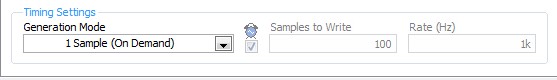
- Configure your analog output DAQ Assistant for output on the 9264 ao0, leave all default settings except for the generation Mode, you should change it to 1 sample (on request).
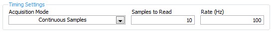
- Configure your analog input DAQ Assistant enter ai18, keep all the default settings again except for sync settings, which should resemble the following:
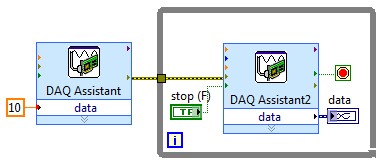
- Your drawing should look like this:
If you do this and you encounter problems with your sensor or its response after the datasheet (or at least the manufacturer and part number), and I'll look into it further.
- Configure your analog output DAQ Assistant for output on the 9264 ao0, leave all default settings except for the generation Mode, you should change it to 1 sample (on request).
-
I am acquiring several channels of analog voltage input at the same time, I need to send an output analog two seconds after the start of the entry.
I'm running an experience with accelerometers on a query table.
I start the trigger and the table remains still for two seconds, which allows a reference level for all sensors.
Then the output signal of the VI removes the break in the motor controller.
The speed measured by the encoder is sent to one of the input channels.In this way, our accel and speed data are synchronized.
After it acquired the analog input data out put must be reset to zero.
MULTI.vi I've updated the link above works of VI, I used a property node to solve the problem.
-
How to control the two analog outputs at a time
I'm new to LabVIEW and have some problems in DAQmx with control outputs analog multiple.
I want to set up a platform using BNC-2110 and PCIe6363 to control two rotating mirrors. The problem that I can only give an output (AO0 or AO1) at a time and I really have no idea how revise my LabVIEW diagram to control two outputs at the same time I met. I tried to change the outputs and it keeps a mirror turning instead of the old. Could someone help me with my problem and I would really appreciate. This is my blocked diagram and front.
Hi zrmaker,
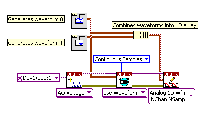
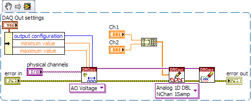
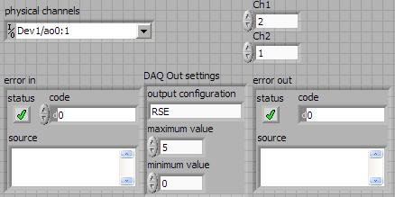
As mentioned by RavensFan, you should not create 2 analog outputs different tasks if you use AO0 AO1. To your façade > physical control or the channels > select the drop-down list of the control channel physical (s) > Browse > hold down the CTRL + select the AO0 and AO1 > Select OK. Once this is done, you will see that your control or the physical channels has the following input values: "Dev1 / ao0:1" which means that you will access to AO0 AO1.
In regards to writing DAQmx, simply select Analog > multiple channels > samples multiple > 1 waveform (you should get the following: 1 d Analog Waveform NChan NSamp). Once done, you can just use table build to combine 2 different waveforms and plug in this table to DAQmx writing output. The first index will be the output for AO0 value and the other will be for AO1.
You can check this link on how to read or write from several channels: http://digital.ni.com/public.nsf/allkb/0C1ADEF06A54AB2D862575040066FD51
Additional reference:
http://www.NI.com/white-paper/2835/en/Hope that helps.
Warm greetings,
Lennard.C
-
Error-200524 when you try two analog output voltage signals
I am train to the output of two signals to analog voltage simultaneously using Labview 8.2.1. One is a waveform to produce sound, and the other is a trigger on another computer (using labview 6.1). I've been doing error-200524 write DAQmx. Here is a screenshot of my VI:
The error message says:
"Measurements: writing cannot be performed because the number of data channels does not match number of channels in the task."
When writing, provide data for all channels in the task. You can also change the task so that it contains the same number of channels as the written data. "How can I solve this problem? Thank you.
Show you only a waveform in the block diagram.
Here is a picture that shows what I told you to in my previous post.
The waveform connected at element 0 of the 'picture to build' will be emitted on channel 0. The waveform that is connected to the item 1 of the 'picture to build' will be emitted on channel 1. The instance of 'DAQmx writing' is 'Analog 1 D Wfm NChan NSamp.
Hope that is more clear!
d
-
Caculate phase difference between two sine waves
Hey guys
Im having problems with this. I read most of it-related topics, but none of the solutions posted helped me.
I have this small circuit and im taking a few values of voltage using my pc sound card. Data acquisition works well. As you may know, the sine wave read in Terminal resistance has a different phase compared to the dinna wave read to capacitor terminal. I tested the file VI and I can confirm it in the charts that I see out there.
I had trouble identifing the difference in phase (in degrees) between the two waves.
I would appreciate if you could help me with this. Here is my file of VI in case someone can give me some suggestions on how to calculate the difference of phase in degrees. Also, in this VI, there are some tests I did with no good result at all.
Any help will be appreciated
Hi moreins,
I changed the code, check it! I gave two solutions that somehow work to calculate the phase difference.
I would like to know if this solution works for you or not. Good day!
Sincerely,
Krisna Wisnu
-
Greetings,
I use a DAQ Assistant to output a 0 - 5V signal. I added a Triangle pattern at the entrance of the DAQ Assistant.
The point is that I do 0 - 5V and then back to 0V. But the problem is that the DAQ Assistant stops just to 1V.
P.s. I have the DAQ Assistant, in a loop ForThanks in advance
-
simple DMA FIFO reading two analog channels
Hello
I have a question on a method of data transfer between two analog inputs for a simple DMA FIFO in FPGA. The code is described here: http://decibel.ni.com/content/docs/DOC-6303. If I use this method, and I got out in a graph of my host VI, the calendar in the graph reflects the same schedule as the signals that have been entered? Or will they be phase shift between two signals?
Thank you
Grant
Grant:
Because it is not all information of timing with the signals in the FIFO, there will be no lag phase on the chart.
Hope that helps. I would like to know if I forgot something, or who does not explain very well.
Thank you!
-
Several simultaneous analog output channels
I use DAQmx-NOR-USB.
I want to simultaneously generate two analog output signals, i.e. change the two outputs at the same time.
Simple example:
What is happening is that instead of two outputs simultaneous modification, there is 1mS delay:
I want to generate premium output, using two channels, but the delayed response is not acceptable.
Any suggestions?
Hi Seth B,.
Yes, it works!
A note: to make visible this property, I had to turn on "display all the attributes" in the menu "Select filter" (right click on the node property).
Thank you.
-
Align the two signals and measure the Phase Shift
Hello
I do an experiment in which I use the NI USB-6221 DAQ card. The jury is able to make 250 k samples/second. I want to measure two voltages in a circuit and find the phase shift between them at frequencies between 1 and 10000. First I ouputted a wave sinusoidal frequency variable through the Commission and applied to a test circuit. Then I used the Board to measure the two tensions consecutively (thus reducing the maximum sampling frequency at 125 k). I used the signals align VI and measured the two phases and then calculates the phase shift (VI attached in Phase 1). It worked well for the test circuit I built in which the phase shift went way logarithmique.20 degrees ~84.5 degrees and then stabilized. At frequencies above 5 000 Hz phase shift must have remained constant, but it varies more or less 1 degree. When the phase shift is 84.5 degrees, present a degree of variability is not particularly explicit. When I asked my program on the circuit that I really wanted to measure, the phase shift went from-. 5 degrees up to about 1.2 degrees. The change in the values of phase shift at high frequencies (> 3000) was environ.2 degrees. Given the small phase shift, this variation is unacceptable. Now I tried to use a sequence to each blood individually (increase the maximum sampling frequency to 250 k) and then align the two signals and measure the phase of each shift. When I use align it and re - sample Express VI to realign the two signals, I get the message "error 20333 analysis: cannot align two waveforms with dt even if their samples are not clocked in phase." Is it possible to align two signals I describe here? I enclose the new VI as Phase 2
Matthew,
I think I have an idea for at least part of the problem.
I took your program data and deleted stuff DAQ. I have converted the Signal on the chart control and looked then what was going on with the signal analysis.
The output of the Waveforms.vi line has two waveforms, like the entry. However, arrays of Y in the two waveforms are empty! It does not generate an error. After some head scratching, reading the help files and try things out, that's what I think is happening: the time t0 two input signals are 1,031 seconds apart. Since the wavefoms contains 1,000 seconds of data, there is no overlap and may not align them.
I changed the t0 on two waveforms are the same, and it lines up. The number of items in the tables is reduced by one. Then I increased the t0 of 0.1 seconds on the first element. The output had both greater than the entry by dt t0 t0 and the size of the arrays was 224998. Reversing the t0 two elements shifts the phase in the opposite direction.
What that tells me, is that you can not reliably align two waveforms which do not overlap.
I suggest that you go to 2-channel data acquisition and that it accept the reduced sample rate. You won't get the resolution you want, but you should be able to tell if something important happens.
You may be able to improve the equivalent resolution by taking multiple steps with a slight phase shift. This is similar to the way that old oscilloscopes of sampling (analog) worked. Take a series of measures with the signal you are currently using. The make enough average to minimize changes due to noise. Then pass the phase of the signal of excitement to an amount that is smaller than the resolution of phase of sampling rate and repeat the measurements. Recall that I calculated that for a 5 kHz signal sampled at 125kHz, you get a sample every 14.4 degrees. If shift you the phase of 1 degree (to the point/mathematical simulation), you get a different set of samples for excitement. They are always separated by 14.4 degrees. Take another series of measures. Transfer phase another degree and repeat. As long as your sampling clocks are stable enough so that frequency does not drift significantly (and it shouldn't with your equipment), you should be able to get near resolution of what you need. The trade-off is that you need to perform more measurements and may need to keep track of the phase shifts between the various measures.
Lynn
-
Meter with two adjustable phase shift
Hello
In this experimental device, I have a print head a TTL pulse-controlled piezoelectric ink jet delivering uniform droplets on a surface. I use the "time" version of the counter output vi (high-/ low-time) because it allows me to very easily change the characteristics of the droplets. I use a strobe approach for imaging the droplets as they are ejected. Basically, a strobe LED light is pulsed at a frequency that exactly matches that of the inkjet printhead. A CCD camera is used in order to imager droplets, who seem "frozen" on the screen due to the stroboscopic effect. Strobe LED is triggered by a train of pulses TTL (two pulse trains come from exits of meter on my USB-6353 X Series DAQ board).
Of course, I could trigger both the inkjet Printhead and the strobe light with the same output of counter, which would ensure that their frequencies match. But it's really nice to have a 'strobe delay' that allows adjustment of the phase shift between the strobe triggers and printhead. The hardware supplied with the print head has this feature of strobe delay as an external button. It is useful, because you can basically lead through time by turning the button and view the formation of droplets when it leaves the end of the nozzle.
I have a vi that may trigger sometimes the printhead and the flash, but I can't understand how to adjust a phase shift between the two, while the program is running. It should be possible, but I can't get it. I would really appreciate help with this. Attached is the draft code and a diagram which may help to explain what I want to do
Thank you very much
-Matt
No - forget the INITIAL DELAY. It's only for the (first) INITIAL pulse.
You already want to adjust the time / low-time already, no?
So having a new control called PHASE SHIFT, from scratch.
Have a variable called OFFSET PHASE CURRENT, from scratch.
When the PHASE SHIFT is modified (by the user), understand the difference between where he wants to be and where you are (control - PHASE CURRENT OFFSET) and add a lot of time the low TIMES, but only during a cycle. Basically you're stretching of a cycle. Store the new value in the course of PHASE SHIFT variable for next time.
Maybe you are looking for
-
OK, I get all the answers and my last quote came back that she was unable to be delivered, what is happening
-
Using a reference to an xcontrol in a class
Hello. I want to use dynamic distribution OOP-methods to write to Xcontrols on the face before of the main VI. In the image below, I illustrated a very simple example, using static methods. However, as soon as I introduce a strict reference to the Xc
-
Sansa clip 8G stuck on "connected".
Hello My new Sansa 8 G clip gives me a serious headache tonight. So far, it's all good well, but now he's caught everything first not say that it was "written" and wouldn't let me put anything. I have checked a few answers about that problem, disco
-
Problem with the Bluetooth device
I have problem with my bluetooth device... before this my phone normally can send bluetooth to my handphone... but now its can not send and the screen display the warning "Bluetooth device not found. Please make sure that your bluetooth device is con
-
Windows 7 home 64 bit authentic can reactivate or re - register
Help! My home edition of Windows 7 64-bit, genuine and paid for, has been activated for more than a year. Everything was fine until there is a message saying that Windows only authentic not started to appear, with a link for activation of the line 3