Plan of mass removed in 2015?
Hi, can someone check if the plan of mass as a receiver of the shadow has been deleted in CC-2015 in 3D to the Ps?

Tags: Photoshop
Similar Questions
-
Oil paint has been removed from 2015 PS?
Give the oil paint has been removed from the new 2015 PS?
Yes, it has been removed from CC2014, in fact. You can always reload PS CC and recover.
-
Planning method of removal using ODI
I use the planning of the operation property to remove members from the planning by ODI. I have question. If I want to delete UDA only without deleting members, how can I configure that? Here is the configuration of my source file.
Operation UDA_COLUMN nom_membre
ABC udavalue Delete level 0
Thank youIf you want to remove a UDA just perform a normal load but put
for the column of the UDA for example
Parent, Member of the UDA,
Acc1, Acc10,See you soon
John
http://John-Goodwin.blogspot.com/ -
So, I had one Adobe Cloud for just the Photoshop and Lightroom. It was in October. When he asked me if I wanted to update the 2015 Photoshop version I did not hesitate. But then he started a 30 day free trial. After the 30 days he now won't let me use Photoshop. Is there a way to get the 2014 version back so I can still use it for the rest of the year I have with the bundle?
Furthermore, these links may help:
Sign in and check your account indicates the subscription with your adobeid https://www.adobe.com/account.html
Then sign out and back in creative cloud with the same adobe id: http://helpx.adobe.com/creative-cloud/kb/sign-in-out-creative-cloud-desktop-app.html
If you updated to Creative Cloud 2015 and some or all of your CC applications show 'trial start or buy now' in the desktop app creative cloud, or if you launch any product of CC 2015 and the pop up displays a test message window, please check this link for the resolution:
https://helpx.Adobe.com/manage-account-membership/CC-reverts-to-trial.html
Guinot
-
Reinstall Visual studio redistributable x 64 20XX and remove fully AVG 2015
OS: Windows 7 Pro 64-bit
I removed < visual="" studio="" 2012="" x64="" redistributables(x64)avg="" technologies=""> in order to get rid of AVG 2015, which gets stuck on my computer in programs x 86. AVG does not appear in the list of installed programs, and I0bit uninstall program can't find it to delete. AVG does not appear on my desktop.
A search of AVG in all programs revealed the number of entries, but nothing is usable/accessible.
How to re - install the appropriate version of < visual="" studio="" 20xx="" x64="" redistributables=""> ?
How can I permanenantly remove AVG 2015? The adds are causing all sorts of pain and blocking me in fact using the virus software.
I plan to re - install the free version of AVG.
Visit AVG for the removal utility
http://support.Avg.com/SupportArticleView?q=completely%20remove&URLName=how-to-uninstall-AVG&l=en_US
Personally I rarely had problems with standard windows uninstall process. (used on several PCs) This is generally poorly designed that will interrupt the uninstalling of programs, and they leave usually only one file
I stopped using SpyBot some time ago and certainly wouldn't use any option record cleaning
Revo receives reports favorable http://www.revouninstaller.com/
-
Unable to remove the application from planning 11.1.2.2
Hi all
I've removed the Hyperion of EPMA Application Library howerver Planning Application when I click on Navigate-> applications-planning of the workspace, I am still able to see the application of planning that I deleted applications EPMA library. How to completely remove the Planning Application.
Kindly help me.
Kind regards
ASIf you have restarted the service, and it is always the same then you will need to manually delete the app, have a read of planning 11.1.1.3 - manually remove a classic Application
Or if you can still you connect to planning app, then you might try conversion classic back and then delete. To convert back to classic go to manage properties under Administration: EDIT_DIM_ENABLED = TRUE
Restart the services, go to the planning administration and remove the appSee you soon
John
http://John-Goodwin.blogspot.com/ -
How can I remove only one instance shared a member of Hyperion Planning
Hello
Can someone tell me how I can load the Hyperion Planning IKM to remove only specific instance of a shared member of Hyperion Planning? I tried specifying the shared member, the parent of the shared instance, "Shared" as the type of data storage, and 'Level 0 Delete' operation. Instead of delete just the shared under the specified parent instance, however, the IKM deleted member base, which in turn deleted all instances shared member and member data (thing lucky I work in a development environment!). At one point, I thought I had things works as I wanted to, but now I think I must have confused.
Is anyone know definitively that a specific instance of a shared member can be removed the planning and, if so, exactly how do?
Thank you very much.Thank you, well it's good news that it's working now.
See you soon
John
http://John-Goodwin.blogspot.com/ -
Hi all
We have 2 plan types & workforce planning. We remove the 2nd type of plan. What is the best way to remove it.
Is it better to build a new application from scratch? How can do usIt is much safer to start from scratch, there is no built-in method to remove a type of plan.
See you soon
John
http://John-Goodwin.blogspot.com/ -
Hello, Im trying to create a plan of mass for a project im working on. I saw a plan button but that gives me problems because I can't change it. I have my out buried components and all traces in place. How to create a master plan and modify it. I couldn't figure how to add no trace after his in place or by removing all copper. Any help would be greatly appriceated.
Thank you
KevinThere are 2 ways to make a copper plane. You describe is basically a copper 'for' - (Place-> Poweplane...) and it fills a copper area attached to a specific network of the whole plan (less trace/pads). It can cancel - which means that it will not cover the existing tracks and you can set traces after the plane of copper is placed. Also, you can remove brass Islands, and you should be able to select (make sure that the copper area selection filter is enabled). I confirmed to Ultiboard v11.
The other method is box-shaped polygon (you manually specify the vertices) - it's called the copper area (site-> box of copper). Similar to the powerplane it can be attached to a net and can also cancel (cancellation is enabled by default - and you can modify other properties to specify other characteristics) and therefore you can place traces with other net transfers in and through the plan (and they will automatically have a release around them). You can also change the shape of copper area and delete it.
Is there something that I just would like to do but can't? What version do you use?
Kind regards
Pat Noonan
National Instruments
-
Hyperion planning and EAS console is unable to connect Server Essbase
Hyperion 11.1.2.3.502
We had essbaae in active/passive cluster and the environment was ssl is activated.
Recently, we removed the ssl configuration
Now, we are not able to connect to the planning and the Regional service console essbase Server
Have no problem connecting to essbase maxl or view smart server. We were also able to import into fdmee essbase.
Check the data source planning and validation of all the
I am getting following error when you use the Regional service console
Essbase Server: servername:1423 com.essbase.eas.essbase.defs.ServerCommands.Connect 16 December 2015 17:57:15 EST
Error: 103: unexpected error Essbase 1030818
Error: 1040142: NZERROR: nzos_Handshake failed (28864)
Error: 1042006: error network [0]: unable to connect to [cs2chypebp01:1423]
Error: 1030818: failed to connect. Please check if the server and port are correct. If you receive timeout or handshake failure, please check if you have tried to connect to secure the port without keyword secure or disable the port with the secure key word.
When you go to the planning, I get following errors in the log files
[2015 12-16 T 19: 20:10.616 - 05:00] [Planning0] [ERROR] [HSP-09012] [oracle. EPMHSP.olap] [tid: 4] [username: < anonymous >] [ecid: 000003wIIy ^ Bp2l5ovH7iY009W4a0000OQ, 0:1] [APP: PLANNING #11.1.2.0]]
[URI: / HyperionPlanning/faces/PlanningCentral] [SRC_CLASS: com.hyperion.planning.olap.HspEssbasePool] [SRC_METHOD: createObject] Impossible to establish the OLAP connection: {0}. []
com.hyperion.planning.olap.EssbaseException (1030818)
[2015 12-16 T 19: 20:10.618 - 05:00] [Planning0] [ERROR] [HSP-09012] [oracle. EPMHSP.olap] [tid: 4] [username: < anonymous >] [ecid: 000003wIIy ^ Bp2l5ovH7iY009W4a0000OQ, 0:1] [APP: PLANNING #11.1.2.0]]
[URI: / HyperionPlanning/faces/PlanningCentral] [SRC_CLASS: com.hyperion.planning.olap.HspEssbasePool] [SRC_METHOD: getConnectionInternal] could not establish the OLAP connection: {0}. []
java.lang.Exception: no object was created successfully. This may be caused by the following: the OLAP server is not running, the DBMS does not run, the DBMS is running on a different
Rental machine as specified, the name and the password provided was incorrect.
[2015 12-16 T 19: 20:10.192 - 05:00] [Planning0] [ERROR] [HSP-09012] [oracle. EPMHSP.olap] [tid: 4] [username: < anonymous >] [ecid: 000003wIIy ^ Bp2l5ovH7iY009W4a0000OQ, 0:1] [APP: PLANNING #11.1.2.0]]
[URI: / HyperionPlanning/faces/PlanningCentral] [SRC_CLASS: com.hyperion.planning.olap.HspEssbasePool] [SRC_METHOD: createObject] Impossible to establish the OLAP connection: {0}. []
com.hyperion.planning.olap.EssbaseException (1030818)So far, we have made
We have removed the ssl configuration by running the Configurator
Reconfigure the web server
Reconfigure the web server to the logical address
Without success. Can someone help and advise you on what we should consider now
Hello
If you are able to connect to the server of Maxl Essbase.
1. I suggest you to take a look at the Source of data for planning application. Since it is an Active/Passive with SSL configuration URL would now
http://host: port/aps/Essbase? NOMCLUSTER = cluster_name
Note: ssl = true is removed at the end
2.
Change of the APS resolve URLS in the file essbase.cfg. Delete "https" and replace it with 'http' (Ref: https://docs.oracle.com/cd/E17236_01/epm.1112/esb_tech_ref/frameset.htm?apsresolver.html )
3. Regional service Console problem
You may need to cancel some things
a. download jnlp and change the URL, remove port 443 and https. Change it accordingly to http and the port of SST (def 19000). Save and open again.
b. in the Weblogic administration Console, you must disable "Enable the Plugin" some option like this that allow us once the SSL configuration for Regional service
Thank you
Anjum Ara
-
Based on a proposal, I am come this post of Premiere Pro.
The condensed version of my problem:
I asked for the best method to remove the droppings of birds with a Pavilion roof in a unmanned aerial vehicle video I shot. I was directed to this excellent tutorial 'chinfat': After Effects CC 2014 Tutorial - 3D camera Tracking and removal of the object - YouTube
Here is my result:
Thanks j. Simon... He did and it didn't.
The tutorial is very well done and seems pretty easy to follow. I sent the clip to AE, complete step "track camera" as was done in the tutorial, created the solid and the camera, exported a frame to ch, corrections to the upper canopy of the gazebo, sent the image to the AE and it merged with the solid. Unfortunately, unlike his video where the window rest frame simply in place, my awning would not. As and the clip, the 'new' canopy high with the camera. I watched this video, a dozen times or more, and could never understand what I did wrong.
Frustrated, I started above square, but ran into a wall after the stage of the "trail camera. Once the scan is complete, an error appeared: 3D Camera Tracker: size of layer must match composition and use default values for transformation. Therefore, any point of the track have been created. I ran into the same wall several times, and then he threw in the towel.
For later use, that I would like to know what I was doing wrong (IE, why don't the solid does not stay in place) and what is happening with this weird error message?
Thank you.
If you have a perspective of change in the object you want to replace that changes significantly the view of this object then you must replicate this change of perspective in your replacement image. You said:
As and the clip, the 'new' canopy high with the camera.
Makes me think that your aerial shooting starts low so the canopy is seen from the front so the shot moves upwards, you can see the sides and the top of the canopy. If this is the case, you will need to create a 3D model more complex of the canopy, then you can follow the camera.
You could also mean that the canopy does not stick to the gazebo. This means that your path was good or that you have chosen the bad points on the surface.
This is where the screenshots would help. I think that the replacement roof does not stick to the gazebo.
A step which was left aside in the tutorial of good but not perfect was the first step in creating a plan for mass and origin. The second part of the tutorial that may give a false impression, it's that he didn't select enough points on the plan to get exactly the target. If you followed his technique to get a target who has been close to looking like it has been aligned with the plan or the surface you were trying to replace then turned solid so she looked like she was the plan that you were probably out of alignment. To align a solid with a plane you should only rotate about the Z axis. If you need to adjust the X, Y and Z then the follow-up of target are not aligned with the plane. You can get a better alignment of selection of the points until you get the plane to match the drop target. Then after you create the plan, you must check the track to ensure that it holds for it together. If it doesn't hold or stick to the surface and then you have not selected the right drawpoints or you do not have a good track.
You also said that it was of arial images. If it was a quad copter with a GoPro or another camera action then the film is probably warped. This will result to problems when you perform the Camera Tracking in AE AE cameras have perfect lenses. The lens distortion will shake track and cause extreme problems like the object is close to the border of the frame. The solution to this problem is to remove the lens distortion. GoPro Studio has the ability to remove a fisheye and it does a pretty good job. My solution to this kind of problem is to export images from the GoPro uncorrected as a sequence of images can use Lightroom to eliminate lens distortion using their lenses profiles or profiles that I created using a graph of the lens distortion.
Here are the steps to replace the subject perfect using AE camera tracker.
- Plan your photos with limits of perspective and examined the Parallax
- Carefully the film suddenly
- Necessary to make plates own so you can remove objects from the scene
- Choose the photo you want to use and define your best estimate in points, then add a few images to each so that you can cut out the changes
- Export images, so you can request the correction of the objective
- Camera follow your film corrected
- Define an original plan and the ground and make sure that it is good in all of the shooting by adding a new layer of 3D solid from the scene, turning 90 degrees in X and seeing if she keeps track with the scene (by adding a grid to that solid will help)
- Choose track points on the surface you want to replace and add a solid with camera Tracker
- Check to make sure that this solid tracks perfectly
- Turn the replacement solid so that the horizontal or vertical edges line up with the surface you want to replace.
- Find the frame where the surface you want to replace is also great that it'll be in the loop and export that frame to Photoshop for editing
- Make your editing, cut or crop the PSD so that only the visible surface or give yourself some room so that you can roto edges
- Replace solid with the replacement surface in the model
- Correction of distortion to the replacement surface that are necessary because of the perspective Exchange or parallax with corners tools
That's basically it if you use a fixed image. If you do the replacement of surface using another section of the video that moves so you would use a projection map, but that's another topic.
I hope this helps. Looks like when you resorted the track camera that something had changed. If you have a track with success once, then you should be able to do it again if you start from scratch with a model that has been created by selecting the clip in your project Panel new comp from selection. As I said earlier, if there is no distortion of the important goal, it is better to delete this before, then cut the shooting, what can be done in the film window, before you start.
If you want more help then post the shot or give us more details about what you want to do.
-
I want to delete my old software quicken 2015, how do I do this?
I bought today Quicken 2016. He did not remove Quicken 2015 my Mac. I can't figure out how to remove the software. It can't be so difficult...
-
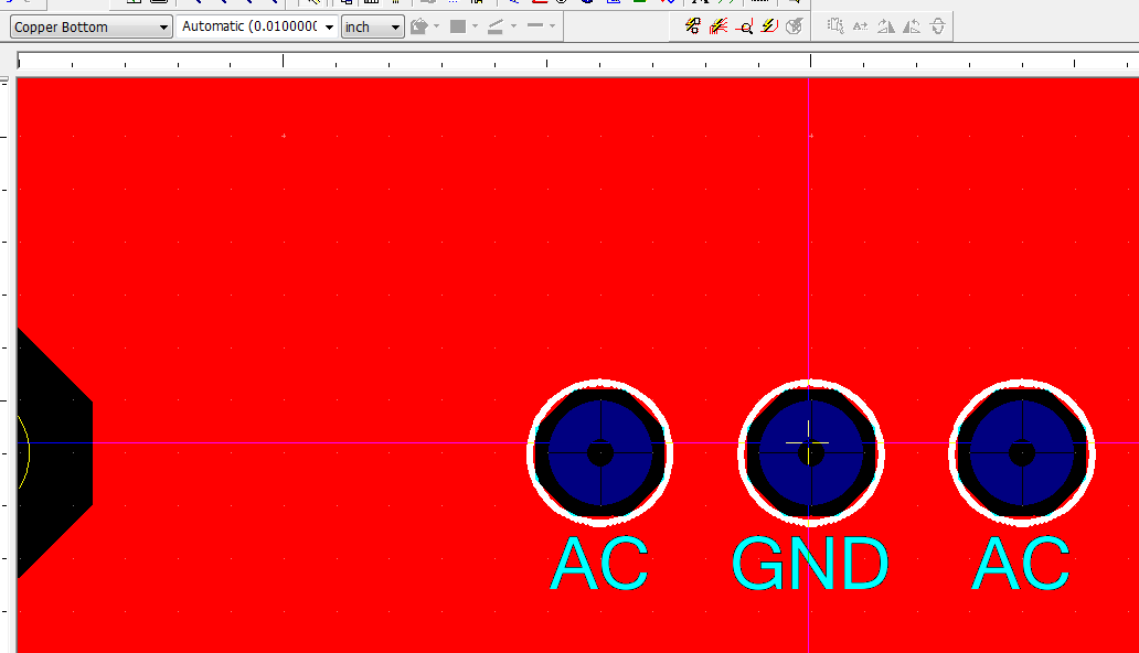
In utiliboard, how electrically connect my hole to the ground (it will come to a Center tap of transformer) to my plan of mass?
There may be a few things here.
1. the most common is that you can have a net 'GND' and a '0' net. 0 references usually analog gnd and "GND" usually refers to a digital pattern. Electrically they are not bound together unless specifically call you this in Multisim (Options-> properties sheet-> PCB tab-> ground option (checkbox). To annotate a forward at this stage.
2. you can't have tied together the plan that you created (what is a copper box or a Powerplane...?) with the net OK. Generally, it will be because the area of copper that it does not prompt you for a name of net before generate the plan. To check turn them on the filter selection of 'Zones of copper' and click twice on the flat surface - go to the "zone of copper" Properties tab and check the correct connection is made.
3. There are times (especially with pins SMT at VIAs), when the connection hole does not appear until you do a connectivity check (even if it is made). For TH pins should not be the case, but its pretty easy to hit the 'check' connectivity once to check (design-> check connectivity)-the style of thermal back-up now will appear if this is the case. It is a known issue and R & D work for the next update.
4. Finally check that the net (GND or '0') is related to the "GND" transformer PIN. To check, go to tools-> editor of Netlist and navigate to the 'MASS' or '0' net and check the connection is made to the correct pin code/refdes.
5. If all else fails, contact our support team and they will be able to guide you through the steps:
http://sine.NI.com/apps/UTF8/NICC.call_me
The Group has indicated if one of them solve you your problem.
Kind regards
Pat Noonan
National Instrumetns
-
Separate 0v track of the ground plane
Hello
Is there a way to have a plan of mass (net 0) and a separate record, which is also on the net 0, the idea being that the separate track is carrying a high current and I'm not being developed on the ground plane. When I draw the trace and then add a ground plan, brings all of this together, ideally I want only 2 to respond to the level of the input connector. I have worked around this in the past by placing a dummy ferrite to the Board of Directors and by assigning the other side of it to DGND but hoped a built-in way to handle this.
Thanks for any advice.
RGS,
Lucither.
RGS,
You have a few methods to do...
Separate reasons of a. threaded and net bridge.
You can implement the design as you have already done - create ground ' net 0' and create a separate ground net "cgnd" or "dgnd", etc... ". For these nets, rather than create a powerplane (Place-> Powerplane...) create a separate copper (site-> box of copper) for each individual network area. Rather than tie them with a component 'false', you can tie them with a net bridge (Place-> Net bridge) to create a star of the Earth at a single point. The only drawback to a net bridge is that it is run only in Ultiboard - there is no reference to him in Multisim. You can create an element of resistance only simulation (black color) in Multisim with a very low value and label this R_netbridge to take this into account and tie between '0 'net and your soil replacement. I also already posted on other patterns and symbols that you can use. I also asked this for a future version of Multisim.
B. only reason net split with polygon separator.
You can create a single ground plane (Place-> Powerplane...) and then use the polygon separator to divide the plan as the strong current flows only back to the point of mass star. The tool is located in the menu (Design-> Spllitter polygon) - Note - I think that its only available on UB PowerPro so. At this point, the user must define how the plane is trimmed. Don't forget that you're not carve out islands that do not connect back to a common point. One tip is to start from the edge of the Board or of the polygon and work toward the point of the star on the ground. Also note that some of the polygon / aircraft parameters can reverse the polygon splitter settings, you may need to adjust the settings if you don't get good results. If you enable the plane and go to properties - tab "Copper Zone" has the vacuum/Island settings I give caution all.
C. create unique net, copper area allows to separate
You can create a single net, but then use the place-> copper area to separate the plane manually as needed. The polygon tool lets you create individual islands - and you have to manually link them to a single point.
Kind regards
Pat
-
Hi all
I'm having a problem with creation of UN ultiboard PCB. I placed a plan of mass on the top brass. In the classic view, it seems the entire PCB. In the 3D preview, it only covers certain areas... (Please see attached screenshot)
Any idea on how to make the mass on the PCB set plan?
I use the student Ultiboard 12 version.
Hey,.
I placed a request for corrective action on this issue, but until then, yes it seems that your work around is the only way to get this working. For manufacturing, file gerber should have no problem be it well, seems that only rendering is bad.
Thank you
Maybe you are looking for
-
The Hermes Apple Watch 2 has sold?
-
Can I use Virgin Media email and gandi mail net on same Thunderbird set up?
Having problem for Thunderbird at the second address Virgin Media email see (new) and webmail not much better. If I create a Gandi net account will both my V Media address 1 and new address Gandi be available the same Thunderbird set up? Regards, Phi
-
Wire collection satellite A210-17R (PSAFG) XP driver
Hello After realizing that my new NB does not come with all the drivers AT ALL, I started searching the web for the work of the drivers for Windows XP. I'll use this thread to post links to these drivers, so that enemies of Windows Vista can use thei
-
Windows XP stop button doesn't give any options to restart, etc It stops just immedietely
original title: Windowsxp home.shutdown button Shutdown (stop) previously suspended for restart, etc. Now, he jumps immediately to the stop. How to restore the original settings?
-
How can I remove a file with the long path?
I got a file and when I try to delete it, it says: the file path is long. Thank you Angelina