point 64 FFT
Hello Sir,
I want to know how to calculate the FFT for 64 points in LabLIEW. There are 64 entries which are complex numbers. My computaton throughout a series of blocks that are given below: -.
1 stage input block
FFT 2 stage-8 points
Unit step 3-multiplier
4 step 8-point FFT
block scene-output 5.
The FFT 8 points calculates the FFT of the first 8 samples then next 8 and so on...
Most of the people a FFT in LabVIEW calculation using FFT VI (it accepts the complex numbers). However, if you need to do this for a homework and show the algorithm, LabVIEW has all the functions of matrix and linear algebra to do this. For more information, see Help.
Tags: NI Software
Similar Questions
-
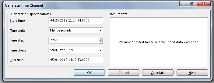
Hi, I work analyze signals of vibration thanks to tiara, data are from 4 to 5 million points in three or four hours, the problem is when I run the analysis FFT only shows me frequencys up to 300 Hz when I know that I measured frequencys of 3 500 Hz.
The measurement parameters:
Frequency: Hz 12800
Number of samples: 1200
Tiara parameters:
Values: 4 757 810
Time: 11:24-14:12
To match my data with time in tiara, I divide the number of values between the seconds of the archipelago.
It was my setting, I Don t know if they are correct and I can´t figure out why it shows me frequencys up to 300 Hz.
Thanks and regards.
Hello Rolando-stc,
I've done some tests and I actually reproduced your problem to get frequency much lower than expected with the FFT. The problem is the way you build your weather channel data. ¿WHERE do you get your data points? The thing is that sometimes the data comes in the form of waveform data. This means that these data already include a channel in time in the same channel, so you don't need to generate a time warp to compute the FFT. If your data is a digital channel only, you need not generate a time warp to compute the FFT. How to calculate the time channel is given the sampling frequency of your data. For example, I have a channel with 325000 points, and the sampling rate was 50000Hz. This means that I have to generate a time with a stage of 20 channel (1/50000) in order to obtain a measure of the FFT of 25000 Hz. If I use a stage of 20 with a selection of field time/Step/bib and 325000 as number of values in the window generating weather channel, I get the channel early to use with my data to compute the FFT. In your case, your sampling rate is 12800Hz, which means that no time should be 78.125us in order to obtain a measure of the FFT of 6400 Hz. In your post, I noticed that you have a different time step. On the other hand, you say that you get a total of 4757810 data points. I do not understand how you get this tip with the sampling rate interval and the time you mentioned. I suggest you create a weather channel using the stage early and check that the data points total is correct. You can use a string of hour or a digital channel, it doesn't really do much since you get the same result for the FFT. I hope this information is useful. Don't forget to post back if you have any questions.
See you soon
-
Why Express PSD gives a different result of amplitude as FFT PSD?
Hello
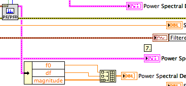
When I use the express VI of spectral measures to trace the power spectral density, I get a different result than when using the FFT PSD VI. The data are the same but the amplitudes are different in the PSD plot. Everyone comes through this?
Thank you
Donners,
The PSD2 and graphic PSD2 are different because you are breastfeeding two extra points in the tables (t0, df). When graphic entry of data in the tables, they interpret not automatically information of t0 and df. Actually they do not yet receive this information. You must program the scales with nodes of property. If you simply draw the order of magnitude, the spectra are very similar.
^ ^ ^ This confuses only the chart!
The spectral forms differ slightly as the power spectrum of FFT and PSD.vi uses a default Hanning window.
Lynn
-
What does not restart in the FFT functions way?
Hi all
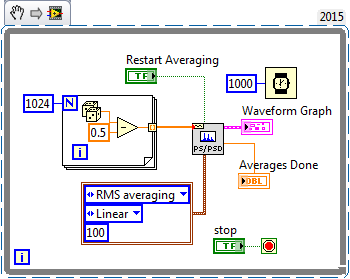
I would like to know what that "restart average" made for the FFT functions. According to aid,"reboot on average indicates if the VI restarts the process chosen medium." If restart on average is set to TRUE, the restart of the VI the selected with an average of process. If reboot on average is set to FALSE, the VI does not restart the process chosen sprawl. The default value is FALSE. When you call this VI for the first time, the averaging process restarts automatically. A typical case when you need to reboot on average is when a major change of entry occurs in the middle of the averaging process"
I realized that the FFT function takes in an array of values and perform the FFT on it. If the FFT function keep a buffer previous values and clears when restart average = true? Because the FFT functions are not Point by point and they take both in all the data to deal with, "a major change of entry occurs in the middle of the averaging process" can be true?
Thank you!
Sigh. I really tried to explain what was going on (probably) with this function, you use (and, I thought naively, you understand), but you got me wrong.
This VI creates a zero average noise signal, providing 1024 points per second. Do you know what should be the power spectrum of the signal? Due to the randomness of the input signal, the power (for a small finished sample) spectrum will also have a random component. If you had several ghosts of power on average, the average would begin to converge with the expected for random noise power spectrum.
If you run this VI and look at the Spectra resulting (on average), you will notice that the first spectrum is the most "spice" and that spectra are averaged, the variation is reduced and diminishes the value of crete (shown by looking at the scale of Amplitude). At any time, you can press "Reset average" and see this... reset the average, the following spectrum shows the growing nose, etc.
It shows the right way to test the function of the power spectrum and discover what he does. My suggestion as to what makes this function seems to be largely correct.
Bob Schor
-
Hello. I really need a help. I have an excel data and then I use a FFT Real vi to get frequency data and wave spectra. Now, I want to use FFT windowed with the same data to excel, but was failed. FFT for real is a vector, while the entry for windowed FFT is an entry point. Can someone help me how to use the data to excel for FFT input with windows? or maybe someone can give me an opinion using "spectral measure. Thank you in advance.
Why not use symmetrical window VI before the FFT VI? He accepts tables and gives you the choice fo all common windows. It is in the Signal Processing > Windows palette.
Lynn
-
Detection of overruns of vibratory limit with FFT
Hi all
We follow a piece of rotating machinery for vibratory limit overruns. Our acquisition of digital data is running at 3333Hz with anti-aliasing in front of the ADC analog filters. We sample at least 5 times on the highest frequency of interest. We then duplicate the measured data and apply several sets of filters band pass to divide the specrum in several frequency buckets watching us then for exeedences the limits defined.
We head to dedicated hardware for our analysis of the frequency of a solution all digital. I have a display FFT showing the linear magnatude of the signal over the frequency. Then, I want to implement limit control on the output of the FFT for real-time tracking. We will always post our data in frequency bins and will have a second look to limit cost overruns after the fact.
As most seems, I had trouble doing exact enough amplitudes of the FFT. Not sure if my problem is spectral leakage or a total lack of understanding FFT. I think it's the latter.
My sample VI has a capture of dynamic data with a real overtaking in the bandwidth of 4-50 Hz. The limit is 5 across. Amplitude in this bandwidth was almost 10. I've included a screenshot of exceeding the limit on the face before of the VI for reference. I have also indexed data saved to the point where the excceedence is visible on the raw data.
I tried using a FFT to visualize this limit so that I can detect the overflow, but I have not been successful. FFT tried several methods and all do not reach the height. Those smarter than me could give it a try? I don't want to run multiple filters of past band by signal in real time, as we do post-processing. I am trying to monitor and display data between 8 and 24 channels. I am concerned about the limits of my processing power to stand in a real-time environment close.
Thanks for the help! And I would like to know if it's just the misapplication of an FFT and if something is better in order.
-Chris.
Lynn,
Thanks for the reply! I tried the inverse FFT road as well, but my implementation was nowhere as clean as yours. I had to spend your complex 1 d inverse FFT block to match the data source however. The actual parameter was twice the amplitude of output. Update attached VI.
I like this solution and you will use Fortunately!
I have an another question though. My company uses not rms. All our limits are in peak (peak-to-peak) / 2. We can also assume that all the waveforms are sinusoidal and so impossible to convert from rms to crete with a root of 2. I'll need a FFT function that does not export in rms. In Matlab, our guys had to code our own FFT function as rms output all built-in functions.
Any ideas on where to find a FFT function that does not export in rms? Annoyingly, I need then inverse FFT in rms as well to match.
-Chris.
-
Exhibitor block signal - Xilinx FFT v7.1 - FlexRIO - FPGA
I use Xilinx FFT v7.1 IP (FPGA - OR 7965R, LabVIEW 2012). I am computing the FFT of real integer 16 bit signed.
Bit 5 signal exposing block block floating point FFT in module v7.1 Xilinx FFT signed or unsigned? Pdf document talks shift to the right of the data output to use the dynamic range, mentions not moving to the left, neither gives sufficient detail on this subject.
Is there a base value as format IEEE floating point should I use to find the correct output value?
I guess that it is unsigned unless you have comments to the contrary. The basic behavior is to keep bits on the left in order to prevent any overflow, so the scale always implies move on to when you think that some of the more significant bits are unused. They provide an example of b00101 = 5, so that indicates there is no bias to apply.
-
How to record a FFT in no time fixed
Hello!
I'm new to LabView and I work with version 12.0. I developed my VI by search through the internet and using the help option, but now I got to a point where I can not find a solution.
I'm analyzing a signal, which i Messure continiously with 2 Mhz. (Puffer = 10 000).
So far, I've saved the FFT by activating the hypothesis of backup through the Boolean operator. This was allowed in order to document the rough behavior of the signal, but I need a continuous record now.
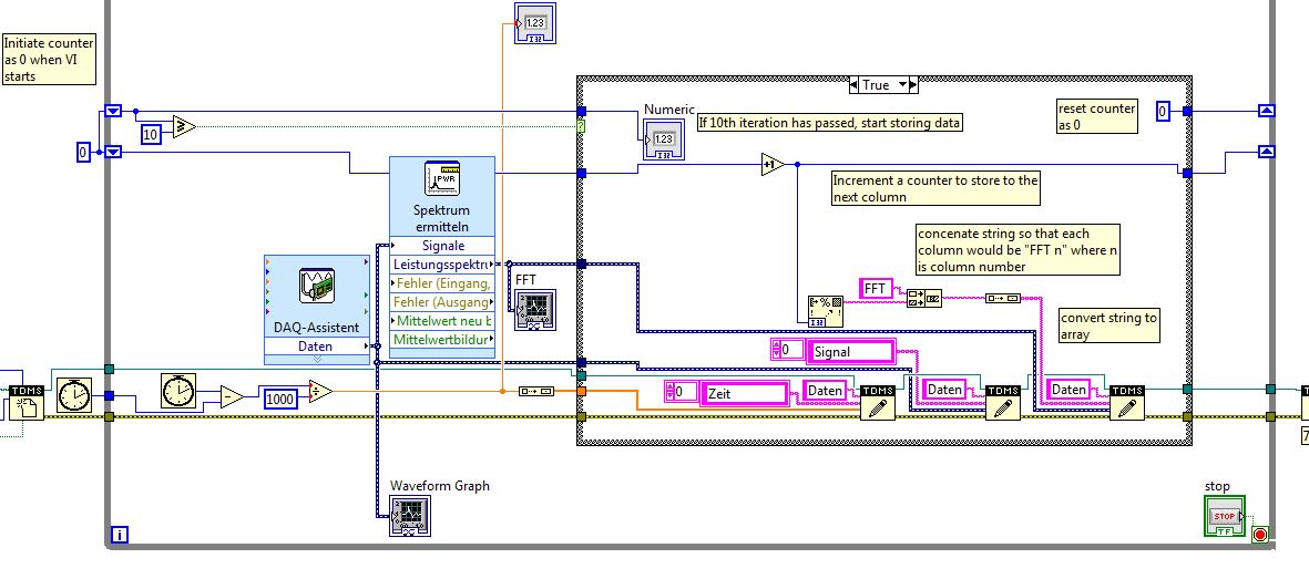
It would be perfect to make a snapshot of the FFT in no time fixed and save data with time according to in an excel file. In the first place, the result should be something like a matrix that I can use for an additional post-processing.
I would like to run this VI more likely a few hours and I realized, that too much data is created.
Is there a possibility to save for example only every 10th point of data or any other way to reduce the amount of data?
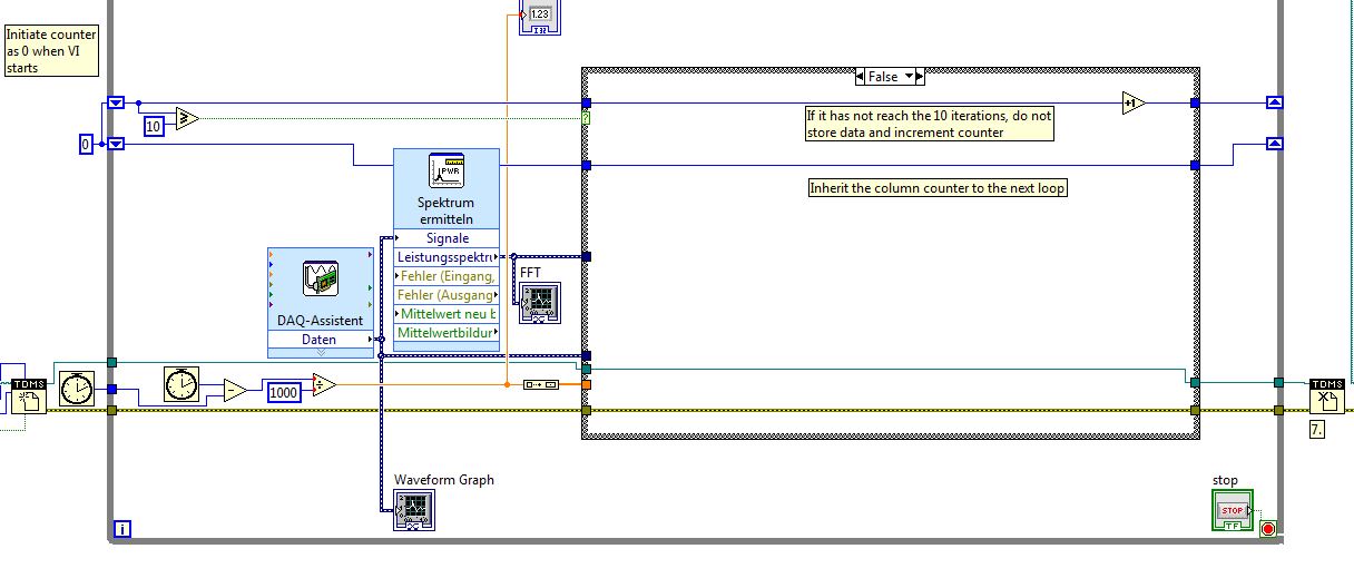
Attached is my attempt so far.
With greetings
Hi, Mr. Pete,.
You are welcome. If you want VI to write to TDMS as shown in your screenshot attached, you can change the code as follows:
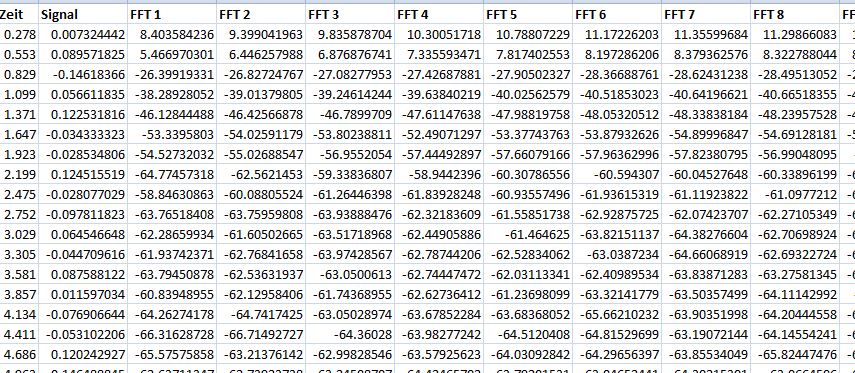
Since for every 'real deal', so we store the data in a column. So what we want to do, is that for each real, we are writing to different column, but with a different as header 1 FFT, FFT 2 and etc. So true as shown below, you must add a counter (we'll call it the column counter) that is incremented every time it's true. Of course, it must initialize the counter of the column outside the while loop so that we start to TFF 1 every time you start the VI. Let's say for the first real trigger of the data storage meter, the meter of the column is equal to 1. However, this counter of the column should be converted to a string, so we use "format in string.vi. So, since one uses a common name, we use FFT at the beginning of the string.vi of conconate. As the results of the conconate string.vi will be 'TNI 1' and data will be stored in a column called "TFF 1". This will be repeated for each increment of counter column (to be noted that this increase count of column occurs only if the case is true).
So given that we do not want this VI writing on the same column continuously while the VI runs continuously. We are to use the shift registers to inherit the value brought from the previous iteration to the next. That means that the column counter will always be 1 until the next 10 data points. So when the iteration of the loop is not equal to 10, the column counter is always at 1 until when the loop iteration is equal to 10 (meaning 10 data point), the box structure is set to true and the column counter is equal to 2 and therefore to store in the column 'FFT 2 '.
If this process continues for the FFT 2 and 3 of the FFT, etc. until you stop the vi.
It will be useful.
Warm greetings,
Lennard.C
-
Cannot write the FFT of the integrated double data
I am a beginner to Labview environment.
I have acceleration Vs time dat file .lvm
Can I get the double integration of this
acceleration data for trip data.
Can I get FFT of displacement and displayed on the graph.
Up to this point VI works
But now if I connect this FFT of moving to 'write the measurement file' then it displays error.
Please help me... and correct the error... All I want is two column data, frequency andthe other of the amplitude of movement.
I have attached all files
I ask you to correct the VI please...
Thanking you!The concepts that you'll want to research are"matrices", "indexing of tables", 'automatic indexing', 'cluster' and 'type of waveform data'.
The loop IN the first VI I sent used the automatic indexation to take each element of a table 1 d of the clusters and perform operations on them separately to convert them to a waveform. Exit tunnel also uses automatic indexing so that the end result is a table 1 d of waveforms. I used the loop, so that no matter how many items appear in the table, you get a corresponding number of signals to the "writing on a file of measures."
In this case, because the output of the FRF is a single cluster (and not an array of clusters), the loop FOR was not necessary. The VI attached this time takes the output of cluster of FRF and maps the cluster to a single components build the wave function and you get a result of unique waveform.
I have no sound and Vibe loaded on my computer at the moment, so I can't run your VI and see the result of the integration of the snout to the Cloaca VI. The output data type is "Table 1 d of waveform" and your indicator and your two FRF can accept only waveforms. I put a function between integration and the indicator/FRF array index, but if there is more than one waveform in the table, it would be the wrong solution. My solution corrects the broken wires but throws waveforms 2,3,4... If they exist.
-
The FFT LabVIEW uses the usual term of eponential:
e ^ (-i * 2 * pi * k * n/N)
Is it possible that I could change this term to include a constant and perform the FFT as usual? that is to replace the exponential term above with something including a constant 'c ':
e ^ (-i * 2 * pi * k * n * c/N)
I actually use a 2D on a square table 2D FFT, but hopefully a solution to the case 1 d above would be easy to apply.
If it's more math than the programming problem, a point in the right direction would be always greatly appreciated!
The only parameter that you can control is N, the number of samples in the dataset. You can try to do 1/N ' = c/n. See if this will give you the results you expect. If c < 1,="" then="" n'=""> N and fill the input data will be required. For otherwise, a reduced supply is necessary. Pay attention to how the data is compressed so that you don't miss any information.
Lynn
-
I'm new to Labview. I need to plot the data (2 passes, one's time, x table, the other is the intensity of the signal, y table) provided by my instructor in the time domain, which I already did. Then I need to convert the data in the frequency domain. What should I do? I tried the FFT function for my table of y. But how do I know the frequency of informaiton? Of table x, I know it's sampling rate is of 2500 Hz. T = 40, N = 100, 000. the effective maxmium frequency should be 1250Hz, right?
And I also need to isolate the signal of 1000 Hz... I'm totally confused.
Hope you can help me. Thanks in advance.
John
Norbert made some good points - you must have a game and maybe get a good book on the signal processing (not specific to LabVIEW).
You're talking about the 'effective' frequency is I guess that the Nyquist frequency = sample rate/2. If that's what you hear, you don't have what about TI-just be aware that the maximum frequency that will show your power spectrum is sample rate/2.
You can isolate a specific time, the field in the way you mention, FFT signal-> zero spectral bins, you're not interested by-> inverse FFT, (not use FFT power spectrum for this). A standard FFT will put on a spectrum double sided, which is symmetrical to the time series that contain no complex numbers, so you will need to virgins at a given location on both sides of the spectrum - which is perhaps what you were talking about RE: effective frequency. Use everything (not only + ve half) to restore the original signal.
The method "virgins a bin and inverse FFT ' is not a 'good' way to get time series in a band for the treatment of the real signal for reasons I won't explain here. You use usually just a filter on time series, including LabVIEW provides several.
-
I use Signal Express but this issue applies to any software. I hope someone can help us with that. I use a card OR-9233 to measure acceleration. I put my 25K sampling rate and put a filter of 10K. I use the software to trigger.
My setup is the accelerometer mounted at the back and the back of the handle of a hammer (down where you would hold it). I was asked to measure the outcome when a small steel ball fell (slightly) to the shock of the hammer head. The accelerometer is a PCB brand 1000g pezioresistive accelerometer, (mechanical BW around 10 kHz).
My question is this: is it possible to perform an FFT when you are just going to "hit" the hammer and measure the result? I'm not measuring the real impact, only the vibrations after it is hit. When I taste, let's dire.5 seconds, I get a nice time signal, and then I apply a FFT. When I shorten the time of acquisition to 40 milliseconds, I'm obviously only enter the beginning and my looks different FFT (highest magnitude), so I started to wonder what is "real"? Operational entities designated and required a repetitive signal of the FFT? Is there a limit to how many "small" or "large" of a time signal that I have?
Looking for some general guidance as my name of field time - frequency domain skills are so right now.
I have the ability to use a sensor to measure impact energy impact, but it is a large sensor. My accelerometer is small. I'm up to the side of the accelerometer AFAIK. I'm wasting my time with a FFT?Kind regards
Jeff Scharpf
Jeff,
Ok. You have a definition of the problem: say the guy marketing you can measure a difference between the two handles.
I guess that both use the same head and the head is solid metal and the handles are of different materials.
You have a way to generate a coherent stimulus. If you always to clear the ball from the same point, you should get a fairly coherent excitation of the hammers. It is possible that the way in which the hammers are hung in the framework could affect the results, but my guess is that this will be a minor effect.
I guess that the answer of the head is a complex resonance excited by the impulse produced by the ball. It will be complicated because the form of the hammer head is asymmetric (unless it's a hammer) and due to the load produced by the handles.
I'll try to measure the reaction of the accelerometer in a few places on the head of the hammer (places where he could not get hit by the ball!). If you can get something that's fairly consistent between the two hammers here, so you have a reference for comparison purposes joint entry. If the answers of the heads are very different, so it will be harder.
Then, I would look at the response of the handles in comparison to the heads. Two accelerometers, an on the head and the other on the handle, measured at the same time are ideal. I would look for differences in depreciation. In other words, the ring die down more quickly on a handful than the other? It is a measure of time, but it may require that the filter to select a unique resonance at a time. I think you want to get as much data as possible, the second half or more as you mentioned earlier. Short segments may be more difficult to interpret and not have al the information you want.
If you can post data, a person may be able to give some other ideas.
Lynn
-
Flags Data Points: copy - lack of flags?
I use DIAdem 2012 to extract a FFT points. Whenever I use the function ' copy of flags Data Points: "created channels are missing the last point data (flag). in other words channel contains n - 1 points.
For the moment, I add an additional indicator to make sure I have copy all the flags that I really need, but I got apprcieate all the tips, I can miss something obvious... I have attached a screenshot.
Thanks in advance!
Padraig
Hello
Thanks for posting. I confirm that you are able to put all the flags you need, but that all those flags don't get copied? If that's what you do, you then select flags more than necessary, then copying all the? You may need to browse to re - select indicators and copy them, then start again.
-
FFT says after removal of offset CC
I'm new to labview pls. I tried to remove the offset CC of a sinusoidal signal generated, but pointed out that the fft does not work well, he sees only the magnitude of the amplitude of the first. However, if I connect the signal directly without removal of dc, it works well. Can someone advise on what to do because it is important that I have remove the DC offset. And I don't want to presume that I am aware of the offset. My VI is attached.
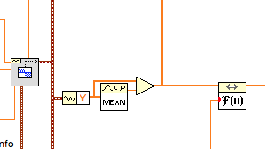
Use a slightly different technique to remove the offset. The DC - RMS.vi on average produces a waveform of offset values while you really want only a single scalar value. Use the Mean.vi (math > probability & statistics palette).
There is no need to feed a waveform to the FFT.vi because it does not appear that the values of Y. If you want a cluster like waveform to feed to the chart, you can create your own from the sample rate and the number of samples or use the FFT (Mag Phase) VI spectrum in the range of Signal Processing.
You also seem to have an aversion to the sons of the straight. It is much easier to read and understand a block diagram if the wires have a minimum number of elbows and do not pass behind other objects.
Lynn
-
Extrapolation of signal with FFT
Hello
I want to extrapolate (generate some outter points a signal given).
My approach is to use a FFT to acquire the signal spectrum,
and, to go back to the time domain of the iFFT to generate the new signal.
But there is no option (iFFT) to specify the size of the generated signal.
For example, if I have a signal of 1 Hz with Fourier, I must be able to generate a signal with an arbitrary length.
Is there a function in LV that generate a signal of varying size for each of Fourier Coef gived in entrance (by the FFT)?
Best regards
Nicolas
Maybe you are looking for
-
Search duplicate files which are not linked to Active Folders
I have several duplicates in my iTunes. Most of the duplicates is more related to active records. I can find how to find duplicates and I can find how to remove them, but there is no sort option that detects files that are not in my current records.
-
Computer laptop 15-r055tu: WATER SPILL
HelloI accidentally spilled tea on my laptop, more exactly on the keyboard, I immediately turned upside down to prevent water to move further off.I skipped what could I possibly can and let dry for about 1 hour and 30 minutes. When I turned it on, he
-
Most of the time my icon text messaging has a 4 number indicating that I have 4 messages not read, but there is nothing there. Looking in my app drawer icon text has also 4. However he sometimes goes far in itself, to return again. Not a big deal, bu
-
Computer starting out of position problems.
If I turned off my computer for a while and then turn it back on, it will not boot Windows. I have to keep turning on and outside and using the f2 and f12 and more, and after that he's finally going to windows xp, so I turn it off, I connect just off
-
running win8.1 & try using 24-hour clock instead of anything like that of am/pm. Help