Problem on myRIO entered analog sampling broadband 50kS/s
Hi all
I have a problem when I want to use the + 10V input analog of myRIO1900 to sample a signal of moving very fast valve (+ 10V analog signal).
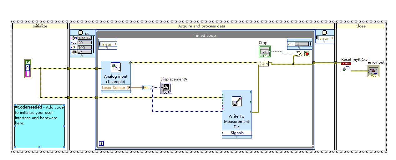
I need less 50kS/s sampling frequency (time 20 s segment two examples of data). According to myRIO specifications analog input has a global 500kS/s sample rate, which means it should be fast enough for me.
I have used a loop in my code and all of the source 1 MHz calendar, timed period 20us (which I need). However, in my LabVIEW code I can get aroud 3ms (333kS/s) time slice (delta t) between two sample data, see file .xls attached, which comes from the function "write to the file of the measurement. I don't know if it is a problem of record data when I use the function "write into the file of the measure", since the time stamp (delta t) of the 'writing on a file of measure' is different from the timestamp (delta t) data that I export waveform graph. But I have to use the function "write into the file of measures" to save the data in real time.
So, how can I know what exactly sampling rate I get to the data? If this isn't the case, that fast how can I do? Is the unit of time or ms for the entry in the data file?
Attachments are my project file, writing to measure (.xls) file and the exported data (.xls) file in the waveform table.
I HERE that very well, if someone can give me some suggestion since I'm a beginner to myRIO and not that familiar with LabVIEW code.
Thanks in advance.
Huan
Since you're using an analog input VI single sample, you are essentially software your acquisition timing (which is timed by your timed loop). It's enough to lower sampling frequencies, but as you try to reach a high sampling rate, you should use the Analog Input Express VI . See here for more info why: http://zone.ni.com/reference/en-XX/help/373925C-01/myriohelp/myrio_one_sample_n_samples/
Tags: NI Hardware
Similar Questions
-
NiDAQmx limits the maximum number of analog samples which can be read / buffer?
I try all the time on a USB-6363 to 1000 Hz 2 channels analog samples. Everything works until I have started to increase the number of samples to read only once in DAQmxReadAnalogF64().
I have set up the buffer in DAQmxCfgSampClkTiming() like twice the amount of samples, I want to read at some point.
Up to about 8000 samples (128 000 bytes: sizeof (double) x 8000 x 2ch) it works and read call returns without delay once all about 8 seconds. Increasing the number of samples other than that, I can no longer read the data (the DAQmxReadAnalogF64() always holler times).
Question: am I running in a limit on the maximum number of samples that can be read or buffered... maybe a DMA limit any? What determines how big you can make the buffer in DAQmxCfgSampClkTiming()?
Maybe it's not obvious, according to the documentation, but if you look at the output value of the parameter samples per channel function DAQmxReadAnalogF64 reading, you'll see that when it times out, he reads what was available when it has expired. So if you're always calling this function, and your timeout value is too short, then you'll always be timeout, but you will always catch all samples. You can view this as the function will return when the buffer is full, or the timeout is reached. That's why we have provided an exit indicating the number of samples read.
As a general rule, ask not read like this with DAQmx. I would recommend registering a callback for EveryNSamples (there is an example that's bundled with the CVI on how to do this), or by specifying a longer period than what it will take to gather real that many samples (in your case, 8000 samples at 1 kHz would be > 8 seconds). The main problem with the polling stations with a short time-out is that you should ignore errors that is not recommended.
-
I have the problem of error 815 in vista broadband
I have problem of error 815 in vista broadband.pls someone give me a solution__
The 815 error code means that the network connection to broadband could not be established on your computer because the remote server is not responding. In addition, I notice that the connection was going well for a few days and broke all of a sudden. In this case, I suggest to contact your Internet provider (ISP) to check first the question.
If the connection can be established using another device/system, please create a new administrator account on the Windows Vista-based computer to solve the problem:
1. click onStart , type the user account and click on the user accounts Control Panel.
2. in the user account control panel, click onaccount manager another .
3. click oncreate a new account , type an account name, select administrator , and then clickcreate an account .
4 logout and login with the new account and establish the connection to check if the problem persists.
I hope this helps!
Brett M.
Windows outreach team
-
Detect the frequency of an analog signal crossing of myRIo AudioIn analog channels
I'm working on a robot firefighting that runs using myRio. I have a small microphone plugged into the port of "AudioIn' of the myRIO, and the robot has to detect a certain frequency (2.8 or 3.5 KHz) to start navigating. The AnalogIn express VI gives me amplitudes of raw tension of type 'Double' but the 'tone Measurment' vi I wanted to use takes in a data type of "Signal". I tried to convert raw data into dynamic data and feeding it, but did not work. A problem is that I can't control the sampling frequency of the express VI AnalogIn (LabView 2013), I appreciate any suggestions on how to do it.
If you install the myRIO 2014 broadband module you can use the Audio input Express VI to sample between 1 and 30 kHz.
You will need to follow the instructions in the myRIO 2014 LabVIEW Toolkit Readme in the section titled the switching between the default and personalities FPGA high speed.
There is also a thread on the MakerHub of LabVIEW where the Toolbox broadband has been used to generate sound , so it might be a good resource to be part of the path.
If you use NEITHER-DAQ hardware, you can get access to the DAQmx driver but myRIO cannot use the DAQmx driver sample data.
Edit: You can also get more help specific myRIO by moving the post on the discussion forum academic hardware products (ELVIS, myDAQ, myRIO) .
-
Problems with signal followed during sampling of the signal
Hello
I'm relatively new to LabVIEW 8.0 and I'm having a problem with being able to monitor the signals that I am gaining two simultaneous analog signals. I have the user to input the frequency of sampling and the length of the sample, and then I starts the scan, but when running the analysis, I don't see no result on the chart if the duration of the sample is passed, at which point all data comes. Previously, I could see the acquisition of real-time data and I don't know what I've done since then have possibly that stop working. I tried to introduce a kind of late for may allow the software to apply the data to the graphics, but I had no success.
I have attached the VI of the data acquisition component.
Thank you so much for reading this.
Hello
I suggest you try these two options:
1. in each iteration of the while loop, add your data to the data of the previous iteration, IE use a shift register to create an Adrien to data that you have acquired. When you save the data in a file, read data from the table and not the current value of the waveform. You can read the data in the table by using a queue, or by using any simple method to pass data between the blocks.
When you use a local variable of the waveform card, you only read the current value in the array, not its history.
2. use a property of waveform graphs node to read the history of the ranking, convert the picture from picture to picture 1 d 2D using cluster of waveform ungroup functions and write to the file, click on "Save".
-
Delay between angle and entered analog on a 6221
Hello
my test setup consists of a (8184 current run LabVIEW RT) embedded PXI controller which uses a PXI-6221 of data acquisition. One of the outputs analog of the 6221 creates a demand for speed that is sent to a servo controller. the servo drives then the test configuration. Between the servo and the remaining test configuration, a quadrature encoder is located. Both the 6221 meters are used to measure the position of the servo (using the trains of pulses A and B) as well as the speed of the servo (frequency of A pulse train). In addition to these counter inputs, some analog inputs of the 6221 serve as well to recored the configuration of test signals.
In this configuration, one of the analog signal has a frequency of n periods per revolution of servo (determined by the mechanical design of the test facility). But when I leave the servo turn to for example 100 rpm, then decelerate from status quo with a constant deceleration and then draw the analog signal against the measured angle, I see clearly that as long as the speed is telling, I n periods per turn (or a passage from my analog AC to zero each 1/2n towers); However, as soon as the slowdown begins, the plot gets stretched along the axis of the angle (so the plot tells me there are less than n analog periods per turn, which is impossible because it would require the mechanical destruction of the facility).
However, I can calculate a position based on speed information signal, as I got to the second counter (by integration of the speed). When I do this for the above velocity profile and draw the analog signal against the calculated angle, I see exactly n times / revolution, no matter how fast the installation program is rotating (just the expected behavior).So, apparently, the speed measured is "in phase" with analog signals, while the measured angle has a "phase error. Draw the angles measured and calculated against the time tells me the same thing: the measured angle is always late (compared to the calculated angle). The period is not constant throughout the measurement; I've seen values between 30 and 170 ms within a single record. Due to this change of variable, inserting a delay for all channels, but the angle is not a great idea.
Unfortunately, calculation of the position of the speed signal is no option for me, because the direction of rotation is changed during measurement; because speed information I have based simply on a frequency of pulse train, it contains no information management, therefore a calculated position would be unaware of the changes of direction.
Does anyone have an idea whence thios delay and what I can do to fix this problem?
Try a position different methods of decoding or exchanging the meter channels has not made a difference.Thank you!
Hey Kevin,
attached you will find the last block diagram (no new translation this time, since no changes have been made that require a), which includes your last suggestions (explicitly start the task of AI, remove the excess constraints) with a flat sequence structure that applies all the preparations of task to finish before the start of the first task (I know I could have achieved the same effect of intelligent routing of the signal error, but I think the code is) better readable this way).
Without OPI, LabVIEW tends to start to have, ao and tasks of the angle of the very different moments, which (for some reason that I don't understand - we have a sample clock based calendar here, and the sample clock is run, well after the three mentioned tasks...) tends to cause delays in the order of several 10-100 ms between tasks. With the structure, this problem is eliminated.
The Sub - VI just above DAQmx writing contains the "conduct" code that I used in the last screen shot to "serialize" the requested speeds - in this way, the table that contains the requirements of speed does not need to be rebuilt.
The code that creates a weather channel frequency implicitly timed measure left the VI shown here in a second VI that is running on the host computer, because everything that involves a calculation and does not require any intzeraction with the DAQ hardware is better placed there (the 850 MHz on the PXI controller celeton is slower than 2 definitiely something host GHz Dual-Core system).
The behavior you mentioned for the task "not started" HERE is what wrote using LabVIEW. I thought the block of relaxation that I had at the beginning would treat the start of the task - at least, the code like this figure repeatedly in the examples that come with LabVIEW.
I don't really understand what has caused the problems I've had - it seems that it was the combination of the measure quickly loop iteration with the start of task based on trigger HERE, but I do not understand what are the mechanisms in the background caused the problem (too forced loop was not the cause; the same block diagram works well with an additional loop timer).
If the solution was composed of the following steps:
-remove the old code calculating speed, replace it with a better code out of the main loop. This allows to
-reduce considerably the frequency of the main loop.
-Pull the DAQmx writing out of the loop, and
s ' ensure that all tasks are started explicitly just before the main loop starts to run.
-Possibly remove excess constraints of the main loop.
-
Problems with timing of analog input PCI-6111
I'm reading the analog input of a PCI-6111, who receives a square signal of 1 KHz with a cycle of 50%. I put the sampling frequency to 1 MHz and wait until the data points are 1 usec outside. When I check the signals received, it appears that the duration of each period of the square wave is 1.22ms instead of the expected 1.0 ms.
The following is a snippet of what I tried:
int NUM_SAMP = 10000;
DAQmxCreateTask("",&mTaskHandle);DAQmxCreateAIVoltageChan (mTaskHandle,
"(/Dev1/AI0","",DAQmx_Val_Cfg_Default,-10.,10.,DAQmx_Val_Volts,null); "
DAQmxCfgSampClkTiming(mTaskHandle,"",1000000,DAQmx_Val_Rising,DAQmx_Val_ContSamps,NUM_SAMP);
DAQmxReadAnalogF64(mTaskHandle,NUM_SAMP,10.0,DAQmx_Val_GroupByScanNumber,mDataBuf,NUM_SAMP,&numRead,);
Can you tell me what I am doing wrong?
Hello SNL_NB_1167,
A good place to watch code you know works would be the finder of the example. "" "" Open the finder example and navigate to hardware input & output "DAQmx" analog measures ' tension ' ContAcq - IntClk.prj
Run this code and see if you get the same results. If so, then we would know that it's a hardware problem and not a problem with the programming. If you see the correct behavior, then you have code that you can shape your out of. I hope this helps.
-
Entered analog PCI 6251 not extent of tension of a mass flow controller
Hey,.
I have a data PCI 6251 M acquisition with a break in Council SCXI 1302.
I'm trying to measure a 0 - 5v analogue output voltage from a mass flow controller (check picture of PIN)
When I measured with a digital multimeter the voltage of the flow signal (PIN2) and common signal (PIN12) I get a stable right tension between 0 and 5v depending on the flow set up. I can control the amount of the charge by providing a data output set point PIN8 and common PIN12 of the 0 - 5V analog signal.
Now when I connect the signal flow PIN2 and on my DAQ signal common PIN12 AI and AIGND, I don't get readings on my labview VI of the AI. In addition the flow does not meet the setpoint voltage, it get stuck in a range of values no matter how I vary the OD 0 - 5V of data acquisition in setpoint PIN8 and PIN12 common signals.
I have to add that I tried different ports HAVE with results of sam, and I also tried to measure my supply voltage with my HAVE and all the good work.
It seems that the entry of AI affects the AO output voltages to my charge. What would cause this? That would be a problem of impedance adaptation?
Management or ideas are appreciated.
Thank you
Ali T.
Update for anyone that might interest you:
I not connected to the ground of the power of the mass of the signal of FJA FJA.
Once I did the acquisition of data reads all data as expected.
So it turns out not to be a problem of acquisition of data, OR at all, but a game of question for my part, as I suspect is the case with most of the problems.
Jeff Merci for your comments.
Ali T.
-
Problem with DAQmx Schedule VI (sample clock)
Hello to you all,.
I'm new to this forum, please bare with me. I have some experience with LV, but I am relatively new to data acquisition projects. I use LV2009.
I want to make sure that I use the hardware timing (instead of software distribution) in my project so I followed some of the threads here as sugested to use DAQmx Schedule VI. The problem is that no matter how I set the system I get the same error-200300 invalid calendar
type.The project is simple. I encode with 1000 pulses per
Rev and it is mounted on a shaft of a turbine water goes thru. I'm watching the frequency
and so the rotation of the shaft which tells me that the amount of water flows through the turbine. In the end, there will be 2 channels
by every encoder and ~ 3 encoders (turbines) total and calibrated the main meter that will give me constant impulses and all encoders will be compared to this master frequency.I'll use PCI6602 DAQ, but
now, for the development, I use USB6221. Let's say that the
frequency is between 500 Hz and 10 kHz. What I am doing wrong? Or maybe better to ask - what would be the right approach for this project?Thank you
Marty
Hi Marty,
It seems that your question is already answered here, but Jason is correct that the 6221 neither the 6602 support a clock sampling for frequency measurements.
As Jason mentioned, your best bet is also likely set the mode of synchronization for "implied". This means that the frequency value is sampled at the end of each period of your input signal. In addition, a solution that is clocked by the software (On-Demand) might be acceptable.
X Series DAQ devices allow an external sample clock to use for frequency measures (described in the Manual of X series). Frequency of sample-clocked measures are useful in very specific
circumstances, but it does not seem that you need this feature based on what you've described so far.(621 x) bus-powered M series can also be configured to use an external sample as the X series clock but do you not have the same features described in the manual of the X series.
I hope this helps!
-John
-
frequency corresponding problem with myrio!
Currently, I am working with myRIO and Labview 2013 to generate sinusoidal PWM signals.
When I created 'analogue output' tab myRio and connected to the Oscilloscope, oscilloscope waveform could not show me the appropriate frequency combined with a frequency that I gave in labiew. Is there a relationship between the frequency of "the"(myRio tap) of analog input between real-time rate? ". Otherwise, is it certainly possible to calibrate the frequency in labview? Please help me!
-
Problems of synchronization of the sample clock with a frequency of a PXI-6229 counter!
Hi all, I'm having some problems with the synchronization of a frequency meter connected to a liquid flow meter (sensor only have 1 open collector output) with the sample of a PXI-6229 map clock. Someone there willing to give me a little help here would be appreciated?
The problem is that the reading of the meter in the whole loop blocks until the time-out period.
Suggestions for an alternative approach would be too good...

Source code attached.
BR,
/ Roger
It sorted another way!

-
USB-6212: software problem timed task of analog input
Hi all
I have unexpected behavior using a USB-6212.
The code example shows that when I run in sequence two analog DAQmx to task, material entry first a timed, the second software timed, it happens that the first readings of data are all wrong and have the same value for all channels.
The labour code is the following:
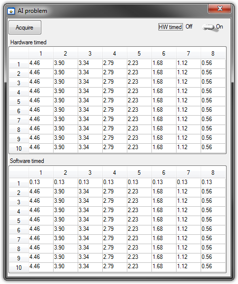
   GetCtrlVal(panelHandle, PANEL_HW, &Switch);

    if (Switch) {
//
// First Task: read 10 rows of values with hardware timing
//
        DAQmxCreateTask("", &htAI);
        DAQmxCreateAIVoltageChan (htAI, MX_DEV_AI, "", DAQmx_Val_NRSE, -10.0, 10.0, DAQmx_Val_Volts, "");
        DAQmxCfgSampClkTiming(htAI,"", SAMPLE_RATE, DAQmx_Val_Rising, DAQmx_Val_ContSamps, 1000);
        DAQmxRegisterEveryNSamplesEvent (htAI, DAQmx_Val_Acquired_Into_Buffer, SAMPLE_RATE, 0, RefreshCB, NULL);
        DAQmxStartTask(htAI);
            Delay(1.0);

        DAQmxStopTask(htAI);
        DAQmxClearTask(htAI);
    }
//
// Second Task:read 10 rows of values with software timing
//
    DAQmxCreateTask("", &htAI);
        DAQmxCreateAIVoltageChan(htAI, MX_DEV_AI, "", DAQmx_Val_NRSE, -10.0, 10.0, DAQmx_Val_Volts, "");
        DAQmxStartTask(htAI);

    for (i=1; i<=10; i++) {
        DAQmxReadAnalogF64(htAI, 1.0, 10.0, DAQmx_Val_GroupByChannel, AcqVoltRow, HW_AI_CHANNELS, &read, 0);
        SetTableCellRangeVals (panelHandle,PANEL_SOFT, MakeRect(i, 1, 1, HW_AI_CHANNELS), AcqVoltRow, VAL_ROW_MAJOR);
        Delay(0.1);
    }
    DAQmxStopTask(htAI);
    DAQmxClearTask(htAI);
A picture is worth a thousand words: analog inputs have been connected to a network of resistance have known values.
The upper table contains timed material acquisitions, the lower the software timed readings... as you can see it the first line is the set of values of 0.13, totally wrong
If the task of timed acquisition of software runs without the earlier (in my demo, that this can be achieved by the switch at the top right), the readings are correct!
Y at - it something I am doing wrong?
I also tried to run the program on USB-6009, but it seems to work properly.
[LabWindows/CVI 2010 SP1 - driver OR-DAQmx 9.4 - Windows 7 x 64]
This problem was corrected by NOR-DAQmx 9.5
324044 NOR USB-621 x task HAVE request returns incorrect data after erasing a task HAVE stamped
-
Problem compiling with Xcode plugin sample
Hi all
I'm having a problem of compiling a sample plugin in the SDK ("BasicPlugin") using Xcode on Mac OS. Xcode build error is "name"CursHandle"unknown type". The error occurs in two source files: AVExpT.h and SafeResources.h. I can't find any header provided with the Acrobat SDK kit that defines the type of CursHandle.
I'm on Mac OS 10.8.4 and Xcode 4.6.3.
The SDK documentation says that the SDK is only compatible with Xcode 2.x; elsewhere in the documentation it says that it was compatible with Xcode 3.2 and 3.3. What is the reason for the above error? It is not possible for me to install the old version of Xcode, because I'm running 10.8 OX, and older versions are not compatible.
I would be very grateful for any help.
Paul
Yes, the software SDK still uses characteristic of carbon (even if Acrobat itself does not use anything carbon). Therefore, you need an older version of Xcode that talks about carbon.
Consider using a virtual machine from a certain flavor to run an earlier version of Mac OS and Xcode.
-
DAQmx error strings (for analog sampling)
I have a simple VI who reads a few analog voltages.
However, if I have the wiring channels ErrorIN/ErrorOut of the DAQmxtiming.vi to the DAQmxread.vi the tensions are no longer displayed.
Someone knows why this happens?
I found that I had some of the VI was out of oder.
He didn't like me using the DAQmxtiming.vi after the DAQmxstarttask.vi.
Thanks for the help.
-
Problem blackBerry Smartphones enter the PIN for first use
Hello, everyone,
I just got a Blackberry Curve 9300 and tries to start with her... The first step is to enter the PIN, which I assume is the PIN in the box. It is a code of 8 characters, alphanumeric characters. When I try to enter the PIN code, the field accepts only 7 characters. In addition, because the PIN is hidden when it is typed, I can't verify the characters that I'm going home.
The web pages without no doubt useful and demos on the site of Blackberry are gone for this model, I get a "404 page not found" message.
Any advice will be most appreciated!
Thank you
Margaret Doyle
Ditto what jamead said: If you or your company has a safety on the SIM lock, then the PIN will be required at startup.

Maybe you are looking for
-
iWatch activity - please confirm there is no auto-pause function. Whatever activity I have to manually, select pause and remember to restart each time. Some competitors have auto pause that implements a temporary cessation of the program when delet
-
Form FF tag FormData why add fields SLnewses and WPTLNG?
I send the data form by using ajax and displaying a FormData.The server receives the correct data and additional fields, i.e.: SLnewses = 1WPTLNG = 1 Best regards John Rossati
-
PCI device and SM Bus, MISSING controller and impossible to INSTALL - HP Pavilion g4 1264ca
I had recently done a clean install on my laptop and when I rebooted, it was missing the drivers for the PCI device and SM BUS controller. When I go to Device Manager and try to reinstall or search the hardware changes, my computer is unable to insta
-
BEFSR41 v. 1 - do not get IP WAN, updated firmware to update
I can get into the setup on the web. I can ping. ipconfig indicates that the LAN IP address is correct (192.168.1.1). All lights are light up properly. My internet connection works correctly (i.e. without the router). I've upgraded to the latest firm
-
Problems of Smartphones blackBerry removal from contact list
Hello! I have problems removal from contact list; some contacts appear updated externally and cannot be removed; do you know what to do in this case? Thank you and best regards...