problem setting daq virtual channel to PCI-6229
Hello
I have trouble to set up a virtual channel to PCI-6229. It comes to LABVIEW 7.1. I am updating a VI in LABVIEW 6.1 to 7.1. When I go through the Assistant of MAX, I get it configured how exactly it is about the version of LABVIEW 6.1, but then under device, there are not listed, although MAX recognizes the labview map in the NOR-DAQmx devices section.
Please help me on this one, as I'm new to labview and cannot find another way for this VI to work but with virtual Renault.
Thank you
Hello
The PCI-6229 is a map of series M and it is supported only by DAQmx Device Driver
Since you MENTIONED that it is the virtual channels in LabVIEW 6.1, your old VI must use of the API OR-DAQ traditional (old)
Howerver the transition from the traditional DAQ in the DAQmx will certainly not be a major concern for you
Since you're new to LabVIEW, you can quickly adapt to the use of DAQmx
The following links should help you to learn and get into programming with DAQmx
http://zone.NI.com/DevZone/CDA/tut/p/ID/3021
http://digital.NI.com/public.nsf/allkb/BB06D0620FDD7ADB86256D2700557BFC
http://zone.NI.com/DevZone/CDA/tut/p/ID/5375
http://zone.NI.com/DevZone/CDA/tut/p/ID/2744
http://zone.NI.com/DevZone/CDA/tut/p/ID/4342
No matter what other assistanceyou seek, let us know
Kind regards
Dev
Tags: NI Hardware
Similar Questions
-
problems syncing multifunction with PCI-6229
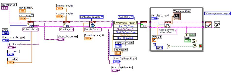
Hi, I use PCI-6229 and LabVIEW 8.0 for synchronized of the thermocouples and voltage measurements. The diagram is attached here. Here are my questions:
(1) with the analog inputs of TC is ranked very first and followed with inputs analog voltage, as shown in the diagram, it works fine. But once the tension AIs are placed first and followed with AIs for thermocouples, thermocouple reading makes no sense, for example telling 25 deg C, the program shows strong fluctuating temperature 10-80 deg C.
(2) the delay time using DAQmx Trigger, here I put the Start.Delay = 2, Start.DelayUnits = ticks. And sampling rate = 1000 Hz for sample clock VI. Then, is equal to 2 X (1/1000 second) delay time = 2ms? If no deadline is set, which is the time between the trigger signal and actural reading? Will it be the time device resolution 50 ns?
All entries would be very appreciated.
Hi Matt11,
(1) the order that you specify strings in your task will affect the order of scanning. In other words, when you add the channels voltage before channels of temperature, the material can enjoy the tension or s channels followed by the string (s) temperature. Since the 6229 is multiplexed, it comes to each channel sequentially switching in a single ADC. In your case, it seems that the tension on the ADC to measure voltage not had time to resolve completely prior to taking the measure of temperature. We refer to this sometimes as ghosts in extreme cases where the value measured on channel b mimics the tension on the channel.
I think that you have found that you can get this by adding the TC task first. You could probably also get the same result by allowing more break-in between channels on your scan list. You can set the time between the channels with a Timing DAQmx property node (you can set the property is the clock frequency convert, which is the opposite of a waiting time). For slow sampling rates, sets DAQmx convert a default clock rate up to a minimum of 1/14 US (on the x 622). If your overall sample rate is less than 1/14 us (about 71 kHz) then you should have room to lower the clock rate to convert more of this if you wish to allow more time to settle between the channels.
I'm a little surprised that you see errors because of it (generally, the problem comes from a signal source of high imepdance measure or when sampling at higher rates), but then again, the temperature measurement would be very sensitive to small voltage fluctuations since you deal with thermocouple voltages at room temperature. Given the order of scanning affects your measure the problem is almost certainly introduced leaving not enough time for the ADC to settle after reading your string tension.
(2) ticks means actually timebase tick rather than the graduations to sample. The minimum is always 2, but this match 2 graduations of 20 MHz (100 ns) time base from which the sample clock (unless you choose otherwise or specify a sampling rate less than 20 MHz / 2 ^ 32), instead of 2 graduations of the 1 kHz sample clock (2 ms). In fact the trigger is probably performed asynchronously at the base of your time, if you are anywhere between the graduations of 1-2 the basis of delay time (50-100 ns) according to the relative phase of the trigger to the time base. If no time limit is set, the default value according to me is still 2 ticks which is the minimum that allows hardware (you can check on your own by reading the property node if you wish).
These points should be compatible between different driver versions, with the exception that DAQmx chose by default convert rate differently in earlier versions of 7.4. Select the conversion rate is a compromise between the settling of deadlines and the channels are sampled how "simultaneously" on the MULTIPLEXED Board. The final result in point 7.4 of DAQmx was a compromise apparently arbitrary add 10 US for the minimum conversion period and use this as the maximum by default between the channels. The user can of course always set the clock to convert to all what best fits their application (in your case, you might want to allow a settlement more between each channel).
Best regards
-
Problem of clock sample e/s digital PCI-6229
Hello
I use PCI-6229. I need to use the digital output channel to generate pulses of 20 kHz 30% duty cycle.
The datasheet shows the sample clock frequency can be 1 M Hz. But in may, only 100KHzTimebase may work to generate. But acctually I need at least 200K Hz.
I've done the Vi is attached. Can someone help me with this problem?
Thank you
Hello ossoo,
The PCI-6229 is not a timing engine digital to create a digital task which runs at 1 MHz, you must use an external sample clock. However, one thing you can do is generate a pulse train at your desired frequency using a meter integrated 6229 and then using this output meter as the sample for your task digital clock. Take a look at the attached amendment, I made to your VI which shows how to build your digital task to 1 MHz using the meter on board. You can change the frequency of the train of impulses of the meter in order to change the frequency of your outputs digital. Please let me know if you have any questions.
Kind regards
-
Duplicate a CTR Global Virtual Channel Max does not update the CO. Pulse.Term setting
Hello
Here is the description of the problem:
MAX version: 4.6.2f1
DAQmx: 9.0.2
Material: cDAQ-9178, output digital OR-9474.
This module to:
- CRT out 0 <-->PFI3
- CTR 1 to <-->PFI7
- TRM 2 on <-->PFI1
- CTR 3 on <-->PFI5
1. in MAX create a Global as an exit CTR on ctr0 virtual channel.
2 use the double in the menu to create a second output of counter. Change its name and replace it with ctr ctr output OUT 1.
3 al ' MAX, the pulse output configuration pane must take into account the change showing the terminal output pointing to the appropriate forum
4 export settings in an INI file and look at the CO. Pulse.Term settings for both channels CTR: they will appear together with the SAME exhortations!
5. with the help of LabVIEW write a vi that generate pulses on these 2 ways, you will get the error-89137 saying that a PFIi resource is already in use. If you look at the Task CO. property Pulse.Terminal, it returns the same to two piles, which is the same error in the ini file.
Can someone at arrival OR this? THX.
Laurent
PS: I posted this message in the LabVIEW Board as I have not found one for MAX
Hello
Corrective action request (CAR) ID: 228780
Best regards
M Ali
Engineering applications
National Instruments
-
DAQ + DAC... OR PCI-6143 + PCI-6731 vs only PCI-6229?
Hi, I try to control a XYZ stage using a feedback program in LabVIEW and wonder about my computer card options for the acquisition of analog data (1) analog inputs and 2 digital outputs.
One suggestion I've gotten is the NI PCI-6143 of data acquisition of analog inputs, more the NI PCI-6731 for digital output to analog.
However, I wonder if the NI PCI-6229 can do the same thing that these 2 cards together can do and for a fraction of their price. The only question I can foresee is a slower rate with the PCI-6229. Other problems with this idea?
Please notify.
Thank you!
Hello clas004,
The PCI-6229 looks like it would be ideal for your situation. According to the two connectors are concerned, the 6229 has two front end connectors. If you check the 622 x specifications OR and look at the stitching down, you can see what is sent to each connector. Since you need 3 analog outputs, you'll need a cable and a block of endings for the second connector as two of the AO signals are on each connector. For cost-efficiency, if the noise is less of a factor for the signals of the AO, you might consider the block of CB-68LP-unshielded endings for the second connection.
As far as the compatibility of the PI functions are concerned, it is likely that they will work, but PI would be able to answer this question the best.
I hope this is useful,
-
PCI-6229 60 Hz noise and drift voltage
I'm having some trouble with an acquisition of data PCI-6229, connected via a CB-68LP. I'm under Labview8.6.1.
The problem is with all the analog inputs. There seems to be a kind of noise in the signal, and I can't determine a reason for this. As it is, I have nothing plugged to the computer other than the CB-68LP. This block of connection and data acquisition have been know (in the month) to function properly.
The problem is that any signal seems to have a loud noise (1V_pp @ 60 Hz) above it. So if I check playback on an analog channel of entry without any link with there will simply be a sine wave a 1Vpp from 60 Hz. In addition, the sine wave slips a lot (a DC offset), usually to settle about us - 6V. I just can not get to a good reason for this. The input will be read in another signal (the same DAQ card or even an external function generator) and reading will look just as (InputSignal + 60 Hz noise + offset CC).
I run the diagnostic tool (version 2.0) and everything seemed to have passed this test, but I don't know if that means anything. Essentially, the jury seems to work, but there is a signal from noise important along the way. I have a hard time thinking that it could be the result of a link between the acquisition of data and the connection block.
I have everything set up in differential mode, and I'm pretty confident in the wiring between the block and the Library to which the block is attached.
I've included what labview bed AI0 when 1. nothing is attached 2. 5.75V_pp @ 360 Hz square wave came. I have also included the results of the diagnostic test.
See you soon,.
-ben
It's awesome Ben,
If you have problems of noise in the future the article following the Developer area has really good information, cordially.
Wiring and considerations of noise for analog signals
Good luck with your application.
Scott M.
-
Impossible to get CB-68LP play nicely with PCI-6229
Hi, I am using a PCI-6229 for 4 analog outputs (call them AO0 - AO3) and 4 inputs analog (call them AI0 - AI3), where I have 2 blocks of connection are the BNC-2110 and CB-68LP.
For now, they are wired like this:
1 BNC-2110 inserted in slot 0 (HAVE 0-15) of the PCI-6229
2 CB-68LP plugged into the connector 1 (HAVE 16-31) of the PCI-6229
The BNC-2110 things part works perfectly. I use it with success for all 4 of the analog inputs and 2 analog outputs. The connection was intuitively simple, by choosing the PCI-6229 s AO0 and AO1 channel assignments in the DAQ Assistant of LabVIEW and simply by plugging in my wiring in terminals AO0 and AO1 BNC to BNC-2110 connector block.
However, I can't understand how to wire the CB-68LP for analog output for AO2 and AO3 channels.
My basic, stripped stable approach to used the NOR Measurement & Automation Explorer:
-J' opened the dialog box indicating "Test panels: NI PCI-6229: 'Dev 1'.
-I click the "Analog output" section and choose from the drop-down list "Channel Name"
-J' I "Dev1/ao0" channels and "Dev1/ao1" working with terminals AO0 and AO1 BNC - 2110, respectively
- but can't figure out how to wire the CB-68LP to work with the 'Dev1/ao2' and ' Dev1/ao3' channels
I think at least part of my problem is that I can't find a pinout for the CB-68LP naming scheme.
Never mind, figured out that list of pins of the PCI-6229 22 and 55 on connector 1 match 22-55 CB-68LP screw terminals, allowing an AO2 (i.e. physical channel "Dev1/ao2"). Similar to AO3 idea. In retrospect, quite simple really
 problem solved.
 -
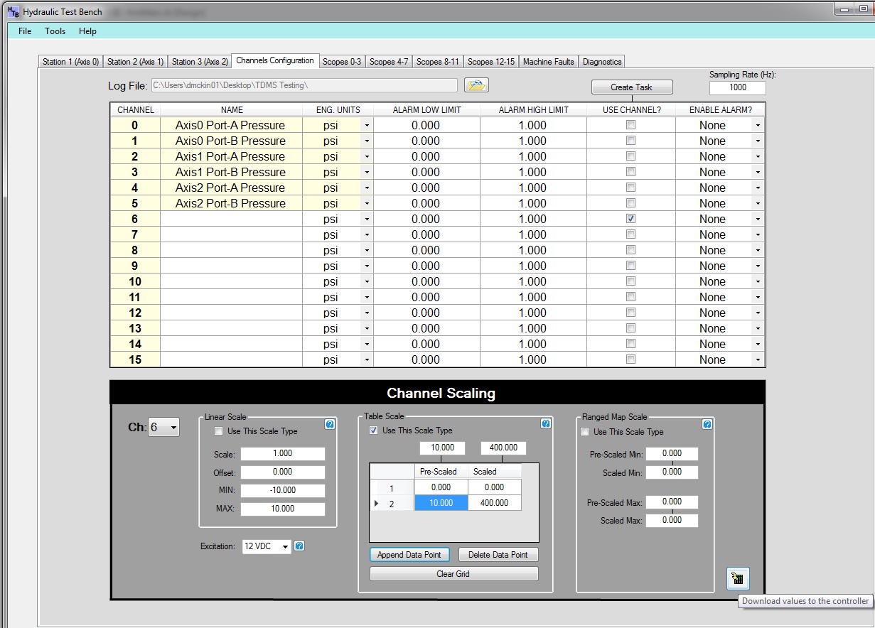
Help the evolution of the scaling of a virtual channel?
Can anyone help me please with this block of code that I have? I don't understand why on the first run it works fine without error exception daq, but on the second run, I get an error.
More detailed, I create a virual channel in a Sub with a button click event. This virtual channel is set to the default values (MIN = - 10, MAX = + 10, linear scale with scale and Offset 1 and 0 respectively).
The click event, is where I'm having difficulties in the other slot. In this Sub I am creating custom scales and assigning values to them, setting the MIN and MAX values of the virtual channel on the same minimum and maximum values of the custom scale being used and assigning custom for the channel finally this new scale virtual to use. The code works for the first run. When I change the scale and then run the code again to a second iteration, I get an Exception of daq error.
Its seems that the MIN and MAX are ready on the second run, but the scaling is not reset to the new scale of values. Can someone check and if so, what is wrong and must be changed in my code?
First execution of the click event of the 'Download' button to assign the custom scale with its values to the virtual chanel... works very well.
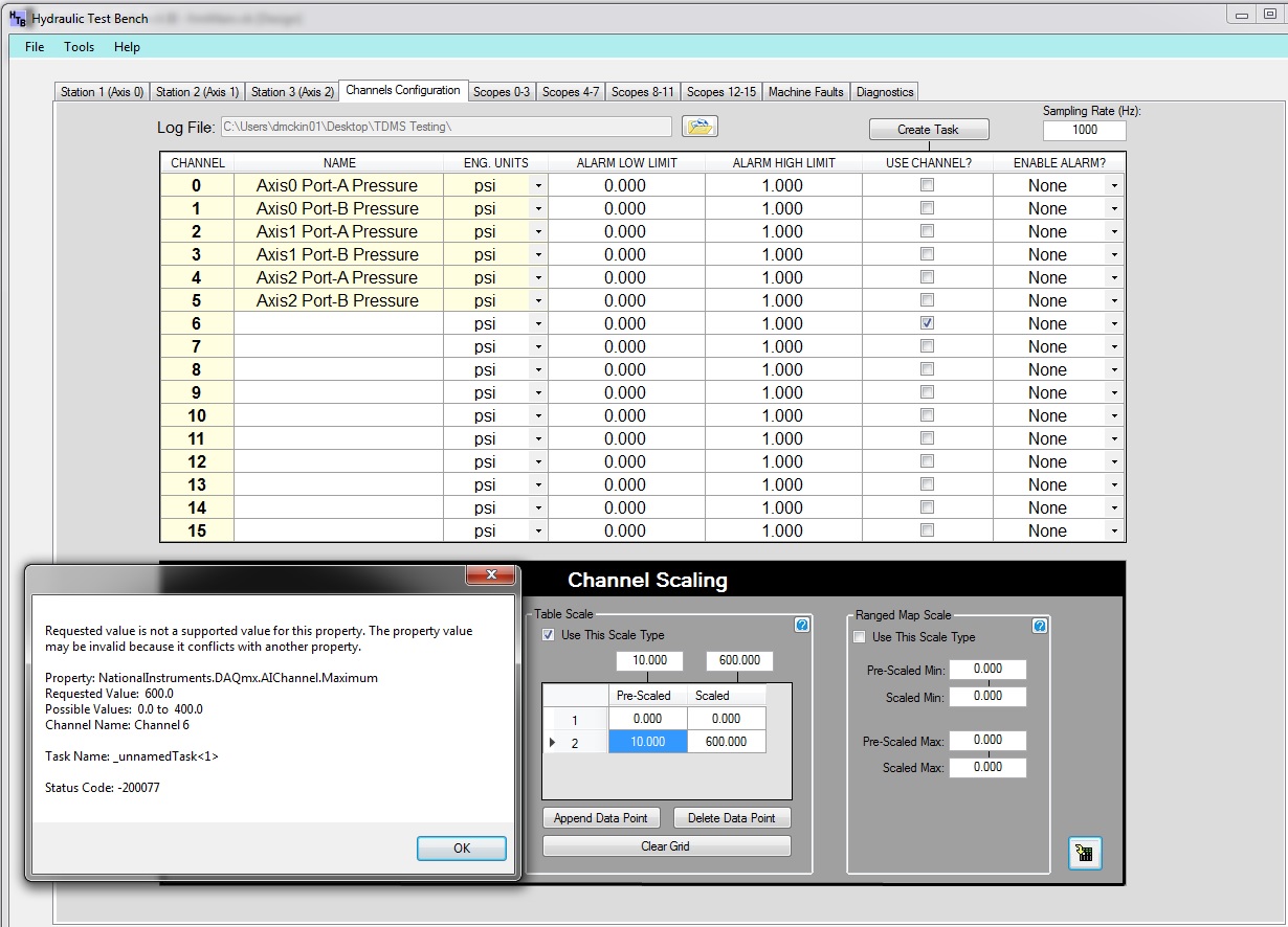
Change the scaling, in the case of 400 to 600 and then run the same code with the 'Download' button click event and I get the daqException error
myTask.Control (TaskAction.Stop)
PreScaledVals.TrimExcess (): PreScaledValsArray = PreScaledVals.ToArray
ScaledVals.TrimExcess (): ScaledValsArray = ScaledVals.ToArrayIf chkBoxTblScale.Checked = True Then
Try
min = ScaledValsArray.First
Max = ScaledValsArray.Last
Catch ex As Exception
MessageBox.Show (ex.) Message & "" scale of table must contain at least two values prééchelonnés and two nationally. ")"
Return
End Try
Else if chkBoxLinScale.Checked = True Then
min = numEdtMIN.Value
Max = numEdtMAX.Value
Else if chkBoxMapScale.Checked = True Then
min = numEdtSMin.Value
Max = numEdtSMax.Value
End IfLinScale = New DAQmx.LinearScale("Linear Scale", scale, offset)
RMPScale = New DAQmx.RangeMapScale("Ranged Map Scale", prescaledMin, prescaledMax, scaledMin, scaledMax)If chkBoxTblScale.Checked = True Then
Try
TblScale = New DAQmx.TableScale ("Table scale", PreScaledValsArray, ScaledValsArray)
Catch ex As DaqException
MessageBox.Show (ex.) Message)
End Try
End If
Try
If cboBoxChannels.Text = "6" then
ChannelSelected = 6
Else if cboBoxChannels.Text = "7" Then
ChannelSelected = 7
Else if cboBoxChannels.Text = '8' then
ChannelSelected = 8
Else if cboBoxChannels.Text = '9' then
ChannelSelected = 9
Else if cboBoxChannels.Text = "10" Then
ChannelSelected = 10
Else if cboBoxChannels.Text = "11" Then
ChannelSelected = 11
Else if cboBoxChannels.Text = "12" Then
ChannelSelected = 12
Else if cboBoxChannels.Text = '13' and then
ChannelSelected = 13
Else if cboBoxChannels.Text = "14" Then
ChannelSelected = 14
Other: ChannelSelected = 15
End IfSelect the ChannelSelected box
Box of 6
myTask.AIChannels (lblCh6Wfg.Text). Minimum = min
myTask.AIChannels (lblCh6Wfg.Text). Maximum = max
If chkBoxLinScale.Checked = True Then
myTask.AIChannels (lblCh6Wfg.Text). CustomScaleName = "linear scale".
Else if chkBoxTblScale.Checked = True Then
myTask.AIChannels (lblCh6Wfg.Text). CustomScaleName = "Table of scale".
Else if chkBoxMapScale.Checked = True Then
myTask.AIChannels (lblCh6Wfg.Text). CustomScaleName = "stood at the map scale.
End IfTblScale = Nothing
RMPScale = Nothing
LinScale = NothingThank you
Look at what you are doing with the New .
If the object does not exist then prompts you to create it, but when it is created, you must be change it.
-
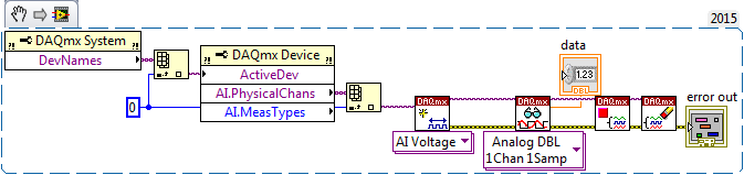
DAQmx create virtual channel (VI) error-229771 reports
Hello
When in a project that I am working to get error-229771 code whenever I try to run 'DAQmx create Virtual Channel (VI)' this does not happen when I create a vi not in a project. The problem is that this project is very large and it if poster impossible to recreate. It's several hundred vi. Y at - it something that I missed in the forums and support that could explain this. I created the VI below in the project and outside the project. In the project, the error occurs outside the project, it runs without any problems.
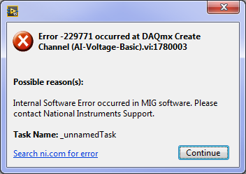
Message:
229771 error occurred at .vi:1780003 DAQmx create channel (I-voltage-Basic)
Possible reasons:
Internal software error has occurred in the MIG software. Please contact the support of National Instruments.
Task name: _unnamedTask
Any help would be appreciated. Thank you, Matt.
LabVIEW version: 15.052(32bit)
OR Max Version: 15.0.f0
NEITHER DAQmx Verson: 15
OS: windows 7 service pack 1
PC: Intel Core i7-2600, 8 GB of ram
Data Aquistion: NEITHER DAQ USB-6289 calibrated June 2015
This code snippet returns the name of the first channel of analog input on the device first, and then tries to create a task for her. The bed of the canal, then close the task.
Error message
Hi Matthew,
Thank you for following up after you fix your problem. I'm glad to hear that you do not encounter this problem more.
Here is an article that lists the reasons for this error (although unfortunately, I cannot pin down which is the exact cause in this case).
http://digital.NI.com/public.nsf/allkb/03123D0E8A36C48E862577A4005B6BAA
NOTE: This article specifies that the error occurs at startup task VI DAQmx. You do not use the start task VI, so the task starts automatically in the DAQmx Read function. The error will occur instead in the DAQmx virtual channel create, that you encounter in your error.
I hope this gives you an idea about what could have gone wrong, and I'm sorry he is no more details.
Good programming!
-
We use PCI-6229 and make the following wiring: released AO1 is connected to the entrance of the AI6, AO0 output is connected to the AI7, Both AI6 AI7 are configured and wired in incremental ways. I have checked the wiring, grounding, plug on the accuracy, the calculator of accuracy on the web site OR.
We have a small application that writes some values to the AO channels, which, in turn, go directly to the channels to HAVE it.
The application writes the values of every 1000 msec, playback is every 50 milliseconds.
That is the problem. For the first pair (AO1-> AI6) values are very close, but the second pair on the same terminal (AO0-> AI7) are very different. And the tension of surplied at AO, the greater the difference.
I read that the accuracy gets worse when the voltage becomes smaller, but why accuracy is so different for channels on the same card?
Here are a few values.
AO1 AI6 AO0 AI7
0.011477 0,011719 0.006868 0,007812
0.011464 0,011719 0.006855 0,007812
0.011503 0,011719 0.006855 0,007812
0.011509 0,011719 0.006797 0,007812
0.011490 0,011719 0.006823 0,007812
0.011477 0,011719 0.006907 0,007812
0.011516 0,011719 0.006823 0,007812
0.011522 0,011719 0.006810 0,007812
0,015625 0.012691 0.008088 0,011719
0,015625 0.015488 0.010854 0,011719
0,015625 0.015566 0.010919 0,011719
0,015625 0.015514 0.010834 0,011719
0,015625 0.015521 0.010867 0,011719
0,015625 0.015527 0.010873 0,011719
0,015625 0.015482 0.010854 0,011719
0,015625 0.015508 0.010880 0,011719
0,015625 0.015495 0.010899 0,011719
0,015625 0.015514 0.010860 0,011719
0,015625 0.015462 0.010821 0,011719
0,015625 0.015514 0.010821 0,011719
0,015625 0.015547 0.010828 0,011719Thanks in advance.
Hello vera,.
Our maps of the M series have a digital-to-analog converter, separate for each channel of the AO. Thus, each channel AO will have slightly different properties and inaccuracies, but they will all conform to specifications.
Kind regards
-
Missing virtual channels PXI-4070 DMM
Problem has been resolved in office. Cannot create global to the DMM virtual channels as the DMM uses the pilot DMM and global virtual channels are a method of the DAQmx and traditional DAQ drivers.
LeeM
NIUK -
Minimum requirements of DAQmx PCI 6229
I am currently converting our are configured to use a PCI-6229 for the analog inputs. We have LABView 7.1 on a Windows XP operating system. I looked at the latest version of DAQmx that would work with LABView 7.1 and found it DAQmx 8.9. When I run the DAQ Assistant I gen an ERROR of INITIALIZATION:
Some components required for publishing are missing. For more information, please contact National Instruments.
Article OR suggest that I put to update to the latest version of the software driver, DAQmx 9.3, to solve this problem, but I do not think that this version works with LABView 7.1.
Does anyone know if the PCI-6229 will work with DAQmx 8.9?
Any newer version of DAQmx will work with LABView 7.1?
And if there is another way to fix the DAQ Assistant error?
Thank you Ahead of time,
WindResearcher
-
Simulating multiple virtual channels per physical channel
I have make steps high speed with several channels simultaneously and am wishing to be able to store the raw data and the version to the unique scale of the data both in tdms files. However, I am wanting to be able to apply properties for the versions on the scale and not scaling separately, mainly to keep the data clean and usable, as well as to ensure that in 6 months when we look at the old data to establish anything confused reports. I know that several virtual channels may be established by a physical channel, but then they must be played in order. Is it possible to simulate this process, or give an another stream of distinct to write to the tdms file properties?
First of all, media DAQmx LabVIEW 8.2 9.0 and later, so you should be able to use the new feature. That being said, for your application, it wouldn't work that well, since you are eager to keep the original DAQ signal so a new signal scale. This function stores the data as you would see in DAQmx Read. Information of scaling you apply can be performed by using a custom in DAQmx scale, but you 'lose' the original file (RAW). However, if you store the scale factor in the properties (as explained below), you could get back to the original data at a later stage (by dividing by the appropriate scale factor). If you buy 2.5 MECH data. / s, you can consider this solution in the interest of performance.
That being said, if you need signals separated for raw and scale, this feature might not do what you are wanting.
Therefore, in answer to your question immediately, if you want these signals to be in the same file, PDM, it's quite possible. Here are comments by looking at your VI to this effect:
1. on the PDM write call and son in a 'group name' such as 'Gross' or 'ladder '. Which splits the data properly to make it obvious what is what.
2. If you want additional information must be stored with the Group (as the scale factor), wire in your group name in the PDM Set properties VI you have and set the 'names' and 'property values' properly.
3 certainly, wire in the same refnum TDMS to all functions of PDM.
Let me know if you have other questions about it.
-
Measurement of the temperature with the PCI-6229
I was announced in an old thread and do not receive and answer, so I thought I try a new.
Link to the old thread: http://forums.ni.com/ni/board/message?board.id=250&thread.id=14920&view=by_date_ascending&page=1
I'm trying to measure temperatures using thermocouples using the PCI-6229 and I use two SBC-68LPR to make the connection. They are not reference on them joints.
After moving down from enugh to careful reading of the old thread I mentioned above and I think I knew what I should do. Here's what I do now:
Create a task - DAQmxCreateTask
Create a channel for this task - DAQmxCreateAIThrmstrChanVex thermistor
Create a number of channels of thermocouple for this task (DAQmxCreateAIThrmcplChan) using the cjcsource DAQmx_Val_Chan option and specifying the string thermistor as the source channel
Start this task - DAQmxStartTask
Get the temperatures - DAQmxReadAnalogF64
Stop the task - DAQmxStopTask
Disable the task - DAQmxClearTask
I have not yet hooked, but I doubt that it is the cause of the error.
A few more details (pardon my Delphi):
Create the channel of the thermistor
TmPcName: = ' Dev1/IA.19 ";
Secret: = DAQmxCreateAIThrmstrChanVex)
TcTaskHandle, / / task handle
@TmPcName, / / physical channel name
@TmChName, / / name of channel
-80, // Min range
80, // Max range
DAQmx_Val_DegC, / / units, ° C
DAQmx_Val_ResistanceConfiguration_4Wire, / / 2-wire, 4-wire, etc.
DAQmx_Val_ExcitationSource_External, / / source of excitement, external
1, / / value of excitement
9.376e-4, // a
2.208e-4, // b
1.276e-7, // c
30000); Resistance of referenceCreation of the channel of thermocouple:
TcPcName: = ' Dev1/ai23;
Secret: = DAQmxCreateAIThrmcplChan)
TcTaskHandle, / / task handle
@TcPcName, / / physical channel name
'', // Channel name
0, // Min range
1000, / / Max range
DAQmx_Val_DegC, / / units
DAQmx_Val_DegC, / / type of Thermocouple
DAQmx_Val_Chan, / / source CJC
25, / / value of CYC, so DAQxm_Val_ConstVal
@TmPcName); CJC channel, so DAQxm_Val_ChanIt looks like 4 scales is required for voltage excitement thermistor measurements.
In addition, it seems that external excitation is necessary in my case, PCI-6229.
Everything works if I use a CJCConstant. When I do this I use the same code to create channels of thermocouple, but I spend creating the channel of the thermistor. When I try to use a CJCChannel I get an error saying "value required is not supported for this property value," which occurs when I call DAQmxStartTask. I don't have no idea of what this message refers to and the best I can tell the properties that I've specified sense. The constant termistor are from actual thermistor, that I found on travailleursduweb.com.
I could also use some help to know how to connect the thermistor. Looks like I need to fab, a thermistor circuit myself, with a stable voltage to power the termistor and use a double-ended analog and reference to the channel.
Thank you
Mike
The error of thermocouple type was a type-o in the post. Thanks for catching it.
I think I found the problem.
I wrote a small program to test for Thermistors and I went to using the routine exctation of tension for a common routine of excitement (... IEX instead of... Vex). I had been by specifying a minimum value less than 0. I changed it from-80 to 0, and it works now. However, I got an error in division by zero, intermittently, when you read a thermistor channel. The error is not in my code. It occurs when you call DAQmxReadAnalogF64 for the first time and I'm not all mathematical related to this call. I'm still looking into it.
-
Physical channel selected does not support the type of output required by virtual channel
I use a box USB-6251. Inside of MAX, I can set the device to Dev1 / ao1 sine wave generation and if he have output a sine wave. When I use DAQmx DAQmxCreateAOFuncGenChan function I get error: selected physical channel does not support the type of output required by virtual channel. The pilot DAQmx does FuncGen on the box USB-6251 or MAX out a set of tensions?
Hi Paul,.
Welcome to the Forums EITHER! The DAQmxCreateAOFuncGenChan is supported only on products Elvis II. For other devices, including the 6251, you must use the ordinary DAQmxCreateAOVoltageChan and create your own data buffer. I would recommend looking in the following example:
Start > all programs > National Instruments > NOR-DAQ > textual Code > ANSI C examples...
Analog on > generate voltage > Cont Gen Volt Wfm - Int Clk
In MAX the Sinewave output is used as a test signal - in this case MAX is a period of the wave sine values to write to the buffer and generate these data. Again, you can produce a sine wave (or any other function) using the AOVoltageChan, but the AOFunctionGenChan is used only with Elvis II. Just generate data points for the sine wave that will produce DAQ hardware.
-John
Maybe you are looking for
-
Install Firefox 32 and 34 do not sync even in a clean
I have been using Firefox Sync since it was an armor called extension and it has worked perfectly so far. I used Firefox on Ubuntu 14.04 Aurora, but I had to uninstall Ubuntu completely from my computer and install Windows 7. The point is that on Win
-
Impossible to update to IOS9.3 on IPAD
I can't go to the software update IOS 9.3 on my IPAD. The software has been downloaded, but when I try to install I get message "IOS9.3 failed verification because you are no longer connected to the internet. Internet works fine can open safari wit
-
I have a beautiful background I want on my computer. I put it and it shows look great but once I get on the internet or even it I just leave my computer for a while, he disappeared, and the background is black again. No idea why this continues to be?
-
Factory recovery G60 Opttion 2
I have a laptop of CTO G60t-200, which has a broken screen. There Windosw Vista with an Intel Dual core processor T6400 with 3 GB of RAM. I replaced it with a G60 - 637CL. It has Windows 7 with an Intel Dual core processor T4400 with 4 GB of RAM. I c
-
Win 7 32 bit sp1 pro has not upgraded to win 10.
After a failure of the upgrade to win 10, I took the option to come back to win 7, such offered in the first month or so, only to find pc display error corrupted or tampered with the Task Scheduler. I tried restoring the restore point saved only to b