Problem of clock sample e/s digital PCI-6229
Hello
I use PCI-6229. I need to use the digital output channel to generate pulses of 20 kHz 30% duty cycle.
The datasheet shows the sample clock frequency can be 1 M Hz. But in may, only 100KHzTimebase may work to generate. But acctually I need at least 200K Hz.
I've done the Vi is attached. Can someone help me with this problem?
Thank you
Hello ossoo,
The PCI-6229 is not a timing engine digital to create a digital task which runs at 1 MHz, you must use an external sample clock. However, one thing you can do is generate a pulse train at your desired frequency using a meter integrated 6229 and then using this output meter as the sample for your task digital clock. Take a look at the attached amendment, I made to your VI which shows how to build your digital task to 1 MHz using the meter on board. You can change the frequency of the train of impulses of the meter in order to change the frequency of your outputs digital. Please let me know if you have any questions.
Kind regards
Tags: NI Hardware
Similar Questions
-
problems syncing multifunction with PCI-6229
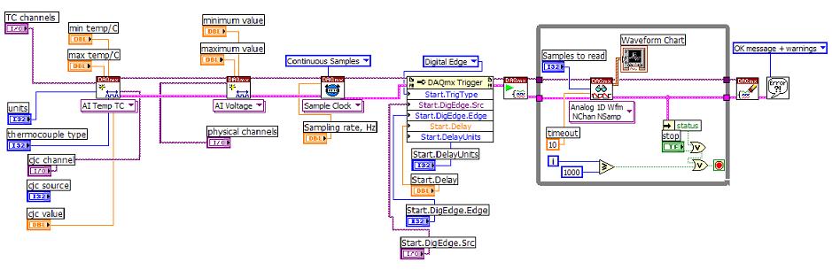
Hi, I use PCI-6229 and LabVIEW 8.0 for synchronized of the thermocouples and voltage measurements. The diagram is attached here. Here are my questions:
(1) with the analog inputs of TC is ranked very first and followed with inputs analog voltage, as shown in the diagram, it works fine. But once the tension AIs are placed first and followed with AIs for thermocouples, thermocouple reading makes no sense, for example telling 25 deg C, the program shows strong fluctuating temperature 10-80 deg C.
(2) the delay time using DAQmx Trigger, here I put the Start.Delay = 2, Start.DelayUnits = ticks. And sampling rate = 1000 Hz for sample clock VI. Then, is equal to 2 X (1/1000 second) delay time = 2ms? If no deadline is set, which is the time between the trigger signal and actural reading? Will it be the time device resolution 50 ns?
All entries would be very appreciated.
Hi Matt11,
(1) the order that you specify strings in your task will affect the order of scanning. In other words, when you add the channels voltage before channels of temperature, the material can enjoy the tension or s channels followed by the string (s) temperature. Since the 6229 is multiplexed, it comes to each channel sequentially switching in a single ADC. In your case, it seems that the tension on the ADC to measure voltage not had time to resolve completely prior to taking the measure of temperature. We refer to this sometimes as ghosts in extreme cases where the value measured on channel b mimics the tension on the channel.
I think that you have found that you can get this by adding the TC task first. You could probably also get the same result by allowing more break-in between channels on your scan list. You can set the time between the channels with a Timing DAQmx property node (you can set the property is the clock frequency convert, which is the opposite of a waiting time). For slow sampling rates, sets DAQmx convert a default clock rate up to a minimum of 1/14 US (on the x 622). If your overall sample rate is less than 1/14 us (about 71 kHz) then you should have room to lower the clock rate to convert more of this if you wish to allow more time to settle between the channels.
I'm a little surprised that you see errors because of it (generally, the problem comes from a signal source of high imepdance measure or when sampling at higher rates), but then again, the temperature measurement would be very sensitive to small voltage fluctuations since you deal with thermocouple voltages at room temperature. Given the order of scanning affects your measure the problem is almost certainly introduced leaving not enough time for the ADC to settle after reading your string tension.
(2) ticks means actually timebase tick rather than the graduations to sample. The minimum is always 2, but this match 2 graduations of 20 MHz (100 ns) time base from which the sample clock (unless you choose otherwise or specify a sampling rate less than 20 MHz / 2 ^ 32), instead of 2 graduations of the 1 kHz sample clock (2 ms). In fact the trigger is probably performed asynchronously at the base of your time, if you are anywhere between the graduations of 1-2 the basis of delay time (50-100 ns) according to the relative phase of the trigger to the time base. If no time limit is set, the default value according to me is still 2 ticks which is the minimum that allows hardware (you can check on your own by reading the property node if you wish).
These points should be compatible between different driver versions, with the exception that DAQmx chose by default convert rate differently in earlier versions of 7.4. Select the conversion rate is a compromise between the settling of deadlines and the channels are sampled how "simultaneously" on the MULTIPLEXED Board. The final result in point 7.4 of DAQmx was a compromise apparently arbitrary add 10 US for the minimum conversion period and use this as the maximum by default between the channels. The user can of course always set the clock to convert to all what best fits their application (in your case, you might want to allow a settlement more between each channel).
Best regards
-
Hi ppl,
I have a question for you.
I have a very similar to the attached picture circuit. also you can find here (http://zone.ni.com/devzone/cda/tut/p/id/3615#toc4 , fig.2) I write some data on analog channels out and then I collect the data in the time loop. I don't understand what exactly is happening when I write the data in the buffer. Let's say I have a table of 2D 2-lines and 62500 columns that I want to write in the output analog channel, then read in the analog channel. I do not understand the meaning of the sample clock. (I read on operations 2 devices simultaneously and blah blah blah). What should be the sample clock frequency in the August channel and the channel of the ain and the number of samples per channel in the ain daqmx channel when I want to collect data? (http://zone.ni.com/devzone/cda/tut/p/id/2835; reading the data in example labview). My problem is that I do not understand what is happening when I load the August channel with data buffer; for example I put the sampling clock rate: 1000; meaning he will write each s 1000 samples of 62500 samples until the end of the samples; all of these samples that I drove from my out channel voltage piezo-beam-scanning engines. which means that each s piezo motors will get 1000 samples of tensions? now, I want to measure. should number of samples in the playback channel I put? I put my daqmx reading in the while loop. Let's say I put 100 Samper useful/channel. so, each itteration in while loop it will read the 1000 samples/channel buffer. How will I know that the buffer is already full with 1000 samples when ain channel tries to read?
The process is therefore more; correct me please if I'm wrong. The sample clock will define us the buffer data rate. For example, I load the 2D matrix: 62500 2rows columns; It will load in the buffer and then there are these samples at the August channel of the rate defined in the clock sample string? Then I want to read from the channel of the ain. What sampling clock frequency should I set for the channel of the ain? If the sample clock rate for the playback channel sets the buffer? for example (I put it there 1000 samples/s; meaning it can read 1000 samples per second?) then what the number of samples should be in the read daqmx channel in the while loop?
Please clarify me this point, I'm confused...
Hi dimani4,
There is a very comprehensive document that answers your questions. You can find this document here.
This article explains the operation of the sample clock frequency and the DAQmx Read reading samples. Quoting the article: "On the hardware side, the Schedule VI DAQmx determines the flow rate of the device/sensor data at the hardware buffer on the data acquisition card.". Here is the 'Timing VI' the sample clock. Then he also explained that "on the software side, the reading VI DAQmx determines the transfer of the data of the buffer material in the software". "." It is making reference to the samples to read the reading VI DAQmx.
I hope this information specific to your questions.
-
By dividing the time base clock sample by N, we're the first sample on pulse 1 or pulse N?
I use an external source for the time base a task of analog input sample clock. I'm dividing down by 100 to get my sample clock. Is could someone please tell me if my first sample clock pulse will be generated on the first impulse of the source of the base of external time, or about the 100th?
I use a M Series device, but can't see a time diagram in the manual that answers my question.
Thank you.
CASE NO.
CERTIFICATION AUTHORITIES,
I don't think it's possible to use the sample clock of 3 kHz on the fast map as the time base clock sample on the slow map and get the first sample to align. The fast card can enjoy on each pulse signal 3 kHz, while the slow card will have to meet the requirement of the initial delay before he can deliver a sample clock. If you turn this initial delay a minimum of two ticks of the time base, the slow card eventually picking around the edges of the clock 2, 102, 202, etc.. You can set the initial delay for 100, which means that the slow card would taste on the edges, 100, 200, 300... but you wouldn't get a card reading slow on the first edge of your sample clock.
Hope that helps,
Dan
-
problem setting daq virtual channel to PCI-6229
Hello
I have trouble to set up a virtual channel to PCI-6229. It comes to LABVIEW 7.1. I am updating a VI in LABVIEW 6.1 to 7.1. When I go through the Assistant of MAX, I get it configured how exactly it is about the version of LABVIEW 6.1, but then under device, there are not listed, although MAX recognizes the labview map in the NOR-DAQmx devices section.
Please help me on this one, as I'm new to labview and cannot find another way for this VI to work but with virtual Renault.
Thank you
Hello
The PCI-6229 is a map of series M and it is supported only by DAQmx Device Driver
Since you MENTIONED that it is the virtual channels in LabVIEW 6.1, your old VI must use of the API OR-DAQ traditional (old)
Howerver the transition from the traditional DAQ in the DAQmx will certainly not be a major concern for you
Since you're new to LabVIEW, you can quickly adapt to the use of DAQmx
The following links should help you to learn and get into programming with DAQmx
http://zone.NI.com/DevZone/CDA/tut/p/ID/3021
http://digital.NI.com/public.nsf/allkb/BB06D0620FDD7ADB86256D2700557BFC
http://zone.NI.com/DevZone/CDA/tut/p/ID/5375
http://zone.NI.com/DevZone/CDA/tut/p/ID/2744
http://zone.NI.com/DevZone/CDA/tut/p/ID/4342
No matter what other assistanceyou seek, let us know
Kind regards
Dev
-
HP Pavilion 17 laptop
There is a problem with the driver for Ralink Bluetooth PCIe Adapter. The driver must be reinstalled.
OT: Driver help
Name: PCIe Ralink Bluetooth adapter Error code: 39 Hello
Thanks for posting the query on the Microsoft Community Forums. You have reached the right place. Let us work together to find the cause of this problem and try to solve.
What is the number of full model of the laptop?
39 error code means Windows cannot load the driver for this hardware device. The driver may be corrupted or missing. To resolve the problem, you will need to uninstall and reinstall the drivers for Ralink Bluetooth PCIe card on the manufacturer's Web site.
I hope this helps. Let us know if you have other problems with Windows in the future.
-
We use PCI-6229 and make the following wiring: released AO1 is connected to the entrance of the AI6, AO0 output is connected to the AI7, Both AI6 AI7 are configured and wired in incremental ways. I have checked the wiring, grounding, plug on the accuracy, the calculator of accuracy on the web site OR.
We have a small application that writes some values to the AO channels, which, in turn, go directly to the channels to HAVE it.
The application writes the values of every 1000 msec, playback is every 50 milliseconds.
That is the problem. For the first pair (AO1-> AI6) values are very close, but the second pair on the same terminal (AO0-> AI7) are very different. And the tension of surplied at AO, the greater the difference.
I read that the accuracy gets worse when the voltage becomes smaller, but why accuracy is so different for channels on the same card?
Here are a few values.
AO1 AI6 AO0 AI7
0.011477 0,011719 0.006868 0,007812
0.011464 0,011719 0.006855 0,007812
0.011503 0,011719 0.006855 0,007812
0.011509 0,011719 0.006797 0,007812
0.011490 0,011719 0.006823 0,007812
0.011477 0,011719 0.006907 0,007812
0.011516 0,011719 0.006823 0,007812
0.011522 0,011719 0.006810 0,007812
0,015625 0.012691 0.008088 0,011719
0,015625 0.015488 0.010854 0,011719
0,015625 0.015566 0.010919 0,011719
0,015625 0.015514 0.010834 0,011719
0,015625 0.015521 0.010867 0,011719
0,015625 0.015527 0.010873 0,011719
0,015625 0.015482 0.010854 0,011719
0,015625 0.015508 0.010880 0,011719
0,015625 0.015495 0.010899 0,011719
0,015625 0.015514 0.010860 0,011719
0,015625 0.015462 0.010821 0,011719
0,015625 0.015514 0.010821 0,011719
0,015625 0.015547 0.010828 0,011719Thanks in advance.
Hello vera,.
Our maps of the M series have a digital-to-analog converter, separate for each channel of the AO. Thus, each channel AO will have slightly different properties and inaccuracies, but they will all conform to specifications.
Kind regards
-
DAQ + DAC... OR PCI-6143 + PCI-6731 vs only PCI-6229?
Hi, I try to control a XYZ stage using a feedback program in LabVIEW and wonder about my computer card options for the acquisition of analog data (1) analog inputs and 2 digital outputs.
One suggestion I've gotten is the NI PCI-6143 of data acquisition of analog inputs, more the NI PCI-6731 for digital output to analog.
However, I wonder if the NI PCI-6229 can do the same thing that these 2 cards together can do and for a fraction of their price. The only question I can foresee is a slower rate with the PCI-6229. Other problems with this idea?
Please notify.
Thank you!
Hello clas004,
The PCI-6229 looks like it would be ideal for your situation. According to the two connectors are concerned, the 6229 has two front end connectors. If you check the 622 x specifications OR and look at the stitching down, you can see what is sent to each connector. Since you need 3 analog outputs, you'll need a cable and a block of endings for the second connector as two of the AO signals are on each connector. For cost-efficiency, if the noise is less of a factor for the signals of the AO, you might consider the block of CB-68LP-unshielded endings for the second connection.
As far as the compatibility of the PI functions are concerned, it is likely that they will work, but PI would be able to answer this question the best.
I hope this is useful,
-
With PCI-6229 NMI Parity error
Currently, I'm trying to get a PCI-6229 to work with one of our lab computers. We'll use LabVIEW 8.5.1 with DAQmx 6.7.1 to program the card. Using our measurement VI owner, the computer will crash at some point (not really in reproducible way) with a blue screen saying "NMI: Parity Check / Memory parity error. All the tests of auto and examples of NOR (delivered with LabVIEW) perform well however.
Most likely, this problem is not a RAM issue (MemTest I tried, different memory chips, different memory banks). Also, the PCI computer bus works very well otherwise (for any other acquisition cards for example). Annoying enough, the card seems to do a great job in an old and slow computer. Which is maybe something to look at? Or are there other ideas?
Our workplace is a Fujitsu-Siemens of Celsius M460 with BIOS version 6.00 rel. 1.09 running Windows XP (32-bit version). The software to use with the card is LabVIEW 8.5.1 with DAQmx 6.7.1.Dear Lutz,
I could reproduce the blue screen, and
changed your program in order to avoid the race condition. What is
actually happens is you want 2 tasks over time the
AOSampleClock as a source before the task of AO started.When
programming as in the example I sent you (see attachment VI), you
shouldn't deal with this blue screen problem more. However, I recognize
that such a thing should not happen even when it's 'bad' programming... I'm going to
inform the development so that it will be corrected with the next DAQmx
version of the driver.Merry Christmas,
P. Lawrence
National Instruments
-
PCI-6229 60 Hz noise and drift voltage
I'm having some trouble with an acquisition of data PCI-6229, connected via a CB-68LP. I'm under Labview8.6.1.
The problem is with all the analog inputs. There seems to be a kind of noise in the signal, and I can't determine a reason for this. As it is, I have nothing plugged to the computer other than the CB-68LP. This block of connection and data acquisition have been know (in the month) to function properly.
The problem is that any signal seems to have a loud noise (1V_pp @ 60 Hz) above it. So if I check playback on an analog channel of entry without any link with there will simply be a sine wave a 1Vpp from 60 Hz. In addition, the sine wave slips a lot (a DC offset), usually to settle about us - 6V. I just can not get to a good reason for this. The input will be read in another signal (the same DAQ card or even an external function generator) and reading will look just as (InputSignal + 60 Hz noise + offset CC).
I run the diagnostic tool (version 2.0) and everything seemed to have passed this test, but I don't know if that means anything. Essentially, the jury seems to work, but there is a signal from noise important along the way. I have a hard time thinking that it could be the result of a link between the acquisition of data and the connection block.
I have everything set up in differential mode, and I'm pretty confident in the wiring between the block and the Library to which the block is attached.
I've included what labview bed AI0 when 1. nothing is attached 2. 5.75V_pp @ 360 Hz square wave came. I have also included the results of the diagnostic test.
See you soon,.
-ben
It's awesome Ben,
If you have problems of noise in the future the article following the Developer area has really good information, cordially.
Wiring and considerations of noise for analog signals
Good luck with your application.
Scott M.
-
Minimum requirements of DAQmx PCI 6229
I am currently converting our are configured to use a PCI-6229 for the analog inputs. We have LABView 7.1 on a Windows XP operating system. I looked at the latest version of DAQmx that would work with LABView 7.1 and found it DAQmx 8.9. When I run the DAQ Assistant I gen an ERROR of INITIALIZATION:
Some components required for publishing are missing. For more information, please contact National Instruments.
Article OR suggest that I put to update to the latest version of the software driver, DAQmx 9.3, to solve this problem, but I do not think that this version works with LABView 7.1.
Does anyone know if the PCI-6229 will work with DAQmx 8.9?
Any newer version of DAQmx will work with LABView 7.1?
And if there is another way to fix the DAQ Assistant error?
Thank you Ahead of time,
WindResearcher
-
Measurement of the temperature with the PCI-6229
I was announced in an old thread and do not receive and answer, so I thought I try a new.
Link to the old thread: http://forums.ni.com/ni/board/message?board.id=250&thread.id=14920&view=by_date_ascending&page=1
I'm trying to measure temperatures using thermocouples using the PCI-6229 and I use two SBC-68LPR to make the connection. They are not reference on them joints.
After moving down from enugh to careful reading of the old thread I mentioned above and I think I knew what I should do. Here's what I do now:
Create a task - DAQmxCreateTask
Create a channel for this task - DAQmxCreateAIThrmstrChanVex thermistor
Create a number of channels of thermocouple for this task (DAQmxCreateAIThrmcplChan) using the cjcsource DAQmx_Val_Chan option and specifying the string thermistor as the source channel
Start this task - DAQmxStartTask
Get the temperatures - DAQmxReadAnalogF64
Stop the task - DAQmxStopTask
Disable the task - DAQmxClearTask
I have not yet hooked, but I doubt that it is the cause of the error.
A few more details (pardon my Delphi):
Create the channel of the thermistor
TmPcName: = ' Dev1/IA.19 ";
Secret: = DAQmxCreateAIThrmstrChanVex)
TcTaskHandle, / / task handle
@TmPcName, / / physical channel name
@TmChName, / / name of channel
-80, // Min range
80, // Max range
DAQmx_Val_DegC, / / units, ° C
DAQmx_Val_ResistanceConfiguration_4Wire, / / 2-wire, 4-wire, etc.
DAQmx_Val_ExcitationSource_External, / / source of excitement, external
1, / / value of excitement
9.376e-4, // a
2.208e-4, // b
1.276e-7, // c
30000); Resistance of referenceCreation of the channel of thermocouple:
TcPcName: = ' Dev1/ai23;
Secret: = DAQmxCreateAIThrmcplChan)
TcTaskHandle, / / task handle
@TcPcName, / / physical channel name
'', // Channel name
0, // Min range
1000, / / Max range
DAQmx_Val_DegC, / / units
DAQmx_Val_DegC, / / type of Thermocouple
DAQmx_Val_Chan, / / source CJC
25, / / value of CYC, so DAQxm_Val_ConstVal
@TmPcName); CJC channel, so DAQxm_Val_ChanIt looks like 4 scales is required for voltage excitement thermistor measurements.
In addition, it seems that external excitation is necessary in my case, PCI-6229.
Everything works if I use a CJCConstant. When I do this I use the same code to create channels of thermocouple, but I spend creating the channel of the thermistor. When I try to use a CJCChannel I get an error saying "value required is not supported for this property value," which occurs when I call DAQmxStartTask. I don't have no idea of what this message refers to and the best I can tell the properties that I've specified sense. The constant termistor are from actual thermistor, that I found on travailleursduweb.com.
I could also use some help to know how to connect the thermistor. Looks like I need to fab, a thermistor circuit myself, with a stable voltage to power the termistor and use a double-ended analog and reference to the channel.
Thank you
Mike
The error of thermocouple type was a type-o in the post. Thanks for catching it.
I think I found the problem.
I wrote a small program to test for Thermistors and I went to using the routine exctation of tension for a common routine of excitement (... IEX instead of... Vex). I had been by specifying a minimum value less than 0. I changed it from-80 to 0, and it works now. However, I got an error in division by zero, intermittently, when you read a thermistor channel. The error is not in my code. It occurs when you call DAQmxReadAnalogF64 for the first time and I'm not all mathematical related to this call. I'm still looking into it.
-
Impossible to get CB-68LP play nicely with PCI-6229
Hi, I am using a PCI-6229 for 4 analog outputs (call them AO0 - AO3) and 4 inputs analog (call them AI0 - AI3), where I have 2 blocks of connection are the BNC-2110 and CB-68LP.
For now, they are wired like this:
1 BNC-2110 inserted in slot 0 (HAVE 0-15) of the PCI-6229
2 CB-68LP plugged into the connector 1 (HAVE 16-31) of the PCI-6229
The BNC-2110 things part works perfectly. I use it with success for all 4 of the analog inputs and 2 analog outputs. The connection was intuitively simple, by choosing the PCI-6229 s AO0 and AO1 channel assignments in the DAQ Assistant of LabVIEW and simply by plugging in my wiring in terminals AO0 and AO1 BNC to BNC-2110 connector block.
However, I can't understand how to wire the CB-68LP for analog output for AO2 and AO3 channels.
My basic, stripped stable approach to used the NOR Measurement & Automation Explorer:
-J' opened the dialog box indicating "Test panels: NI PCI-6229: 'Dev 1'.
-I click the "Analog output" section and choose from the drop-down list "Channel Name"
-J' I "Dev1/ao0" channels and "Dev1/ao1" working with terminals AO0 and AO1 BNC - 2110, respectively
- but can't figure out how to wire the CB-68LP to work with the 'Dev1/ao2' and ' Dev1/ao3' channels
I think at least part of my problem is that I can't find a pinout for the CB-68LP naming scheme.
Never mind, figured out that list of pins of the PCI-6229 22 and 55 on connector 1 match 22-55 CB-68LP screw terminals, allowing an AO2 (i.e. physical channel "Dev1/ao2"). Similar to AO3 idea. In retrospect, quite simple really
 problem solved.
 -
Negative outputs analog of the PCI-6229
I appreciate this question may seem a little primary for some of you, but I spent hours looking for an answer with no luck.
I have a card from e/s NI PCI-6229 M series I want to use to order a proportional hydraulic valve. The valve in question takes input in the range from - 10v to + 10v, which fortunately is the flow of the IO card range.
My question is this; in order to generate a negative voltage (-) through the valve, what I need to connect to the two terminals (AO0 and AO1) AO or can I connect to a single AO (AO0) and the ground terminal (ALWAYS)? Or to say it another way, can the material generate a lower voltage to ground thus creating a negative through the valve potential difference if one is ALWAYS used?
Thank you very much.
James
Hi James,
My mistake because I thought you were using LabVIEW. In theory, you should still be able to set the output programmatically.
This link from the site Web of The MathWorks shows how to vary the values of your analog output when someone was using a PCI device , so it can be useful.
I think the block National Instruments analog output is likely to be also useful.
Having not used the xPC Target before, it's hard to be sure if. I highly recommend using LabVIEW next time
And yes I count not that you went on your wiring in the correct manner.
Kind regards
-
What is the analog input of the NI PCI-6229 impedance?
I am trying to determine the effect of a 12 K resistor that is in series with an analog input of an NI PCI-6229 data acquisition card. Resistance of 12K seems to be part of a RC filter. I have a 0-10 VDC source this supply circuit. What is the impedance of the analog input of the NI PCI-6229 data acquisition card? If it makes any difference, the analog input is connected in differential mode with a 180K resistor to Gnd AI.
Thank you
RWB
Hi, RWB,.
The input impedance is classified in the specifications 10 GOhm. So, the effect of your k 12 resistance should be relatively low. Take care!
Maybe you are looking for
-
How can I configure Messenger to Facebook messages?
Sorry, I can't find any which section for Messenger app on this site, so I had picked a spot at random for this post. I followed the instructions on this site, but it does not work.http://osxdaily.com/2015/04/25/set-Facebook-Messenger-Mac-messages-OS
-
Qosmio F60, PQF65A - how to play blu ray?
Hey people, I had huge difficulties in getting the blu - ray player to play blu - ray disc I've had this laptop second hand and all the manufacturer software has been uninstalled and I had to start from scratch. Currently, I have a Toshiba V3.01.1.07
-
(Programmatically?) how to change the name of the button on the taskbar for an executable
Hello I use LabVIEW 2010SP1. I noticed that the name of an executable task bar button is always its file name (for example if I set "abc.exe" as filename target in the category information properties of the application, the name of the corresponding
-
Wireless disabled during startup
Hey everyone, I have a laptop ASUS G71gx with Windows Vista 64-bit. About two days ago, I noticed when starting up my wireless wouldn't connect automatically. I hit diagnose and repair, and he said that I had no wireless connectivity. I tried reversi
-
Management Web Dell Force10 S series S55
Hello I would like to know if there is a way to enable web management on a S55 dell force10 switch. Thank you.