Problem: The differential mode, measure 1.4 V, USB-6009
Hello world
I am able to charge and discharge the two capacitors, individually.
I use the USB-6009;
Two capacitors, two charts, two analog inputs (AI0 +, AI01-) and (Al1 +, Ai1-);
I have configuredin differential mode; Ok
Problem:
When a capacitor is switched off, it measures 1.4 V
Try to correctly set the task - run the DAQ Assistant to create the task
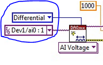
Dev1/ao0 would be much better - Oh, and now that you take the wizard open-Do on the wiring diagram, it offers you
For the PREMIUM of 6009 task mode AI0 is + AI3 is - and you only reserve reserve explicitly AI0 (AI3 line is reserved by seleting the + line in the channel and the declairing it is differentiated)
And give the task/channel a significant name of "MyCap1Discharge" would be useful...
Now let's talk about your electrical engineering:
The input of the 6009 impedance is 144kOhms the resistance of discharge 1MOhm becomes useless as soon as you connect the control AI 6009.
Tags: NI Software
Similar Questions
-
measurement of current with usb-6009
Hi, my name is hung and I am a student in electrical engineering... I'm doing a thesis that the project using Labview and acquisition of data NOR UBS-6009 to simulate the function generator, Oscilloscope, Digital Microsoft (DMM)... and now I'm simulating DMM. I managed to measure the voltage and resistance which i use voltage divider method, but I encountered a problem with the current measurement. The problem is the USB-6009 to measure use the current, it measures an incorrect value. I tried to use the current CQI 0-20mA Sample.vi example but it always measures an incorrect value. If NI USB-6009 supports for the measuring current? Is there a way to measure the currents using USB-6009? Please, help me. This thesis project is so important for me. Thank you.
Hung,
Since you are a student in electrical engineering, I'll show you how to know the answers to your questions.
1. review the specifications for the USB-6009 case. In particular look at the specifications of analog input.
2. How would you measure current if you had only a voltmeter? Use the same method with the USB-6009 case. (Tip: apply the Ohm's law).
General comment: when using any measuring instrument, always consider maximum permitted values at the entrances so that the instrument is not damaged
and the measure is accurate.
Let us know how you do.
Lynn
-
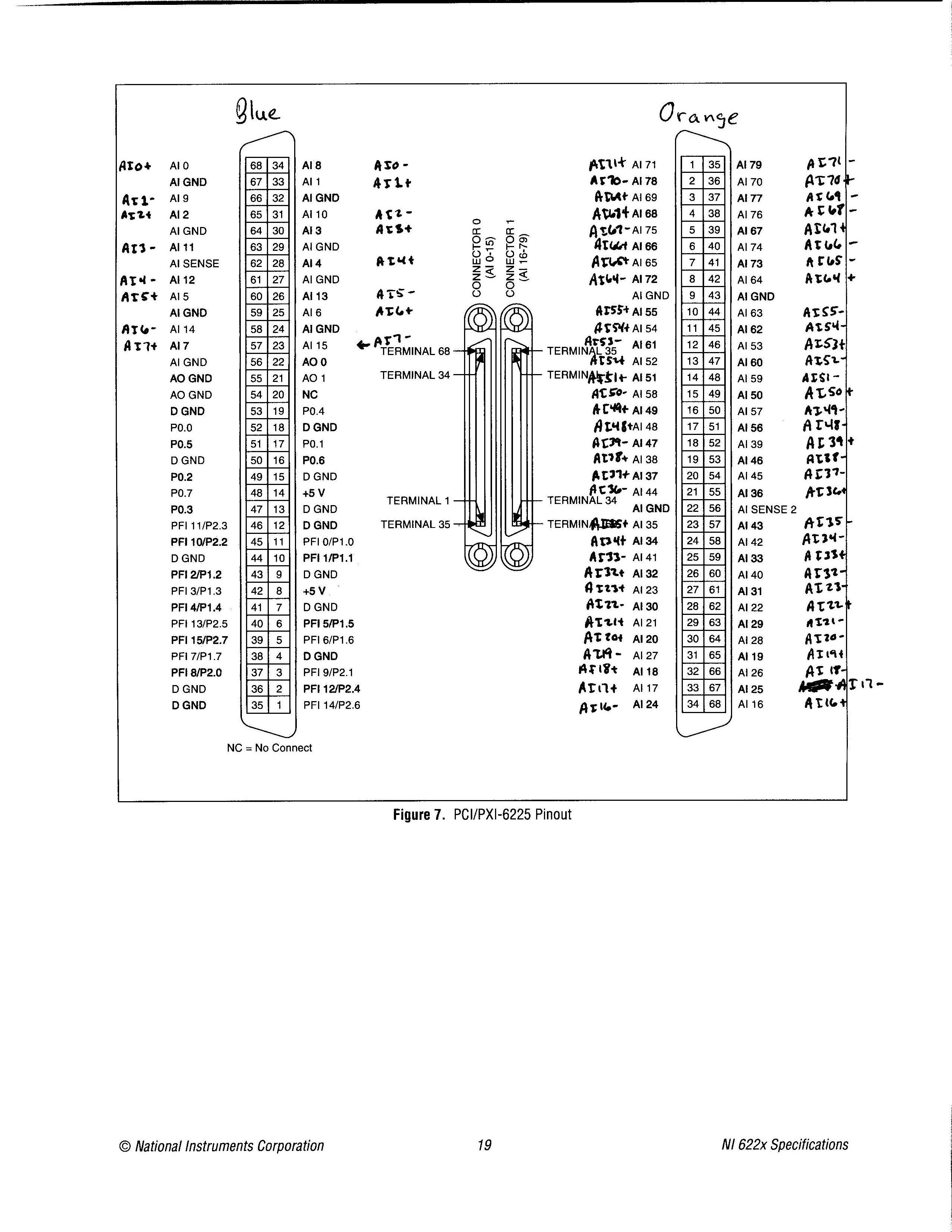
Pinout of the device from the PCI-6225 in differential Mode of I
Simple question: where is the pinout of the device for the card PCI-6225 for differential of analog input mode? I looked in the device list of the pins in MAX, in the NI 622 x specifications document and several other places, but I was not able to find it. I found the pinout for referenced asymmetrical measures, but no differential.
Related issue: most people use devices like the 6225 for no entries analog differential? So why in tarnation do many brand of material OR that upper and lower manuals, looking for the differential input version?
Thank you!
«Referring the number of pins would make it impossible to use the same code when you change maps DAQ.»
I'm not sure I followed here. Can you please explain a little further? Are you referring to the 1-68 0 connector pins and 1-68 pin connector 1? If so, I'm not sure, I followed. A different pinout may not change the code. If I had to replace a 6225 with another equivalent at least DAQmx device as many channels and the device number was the same, then I'd not change all the names of channel in the code, I? It would certainly change the wiring, which is precisely what I'm doing right now.
I know that the analog input channels look like ai0, ai1, etc.. My concern is later: where the jumps occur when you're in differential mode?
I have attached exactly what I would like to see in the documentation of ALL analog input device which allows the differential mode, only with the + and - channel names only and not the labels AI0-AI79. I couldn't find this photo any place, but rather had to laboriously calculate this pinout. If you know where to find this photo, I would be very grateful.
Thanks for the reply.
-
How to set the differential input for personal iotech Daq/3000 mode
Hi all
I currently use personal iotech daq/3000 for the acquisition of data from the accelerometer.
I got readings of the analog input, while there seems to be no configuration for the differential mode.
What I have is:
selection of material - personaldaq / 3000:direct
Double click on, then:
Channel installation, there should be a selection of differential mode, I guess. But this is not.
Thank you very much
Alan
Have you reviewed the C:\Program Files\DASYLab 10.0\manuals\IOtech_DAQ_notes. PDF? Or the help of equipment?
The section of material assistance, using the analog inputs with DASYLab, includes pictures to show how to do this.
Open hardware driver.
Click the line Analog Input Channels, and then right-click to open the properties. This will display a dialog box that allows you to set the properties.
-
OR USB-6009 daq sample following loss, while the loop iteration
Hello
I am trying to acquire and display data measured from a DAQ NI USB-6009 material using Labview 2015. I am using the wizard daq defined for the differential mode and n samples with the sample rate and the total number of samples registration by the user. My problem is that when the specified amount of samples is acquired and the while loop continues to the next iteration, some samples are removed (I know because I tested it acquire a wave of fishing and there is a noticeable artifact in the signal at times where the while loops - I downloaded a file showing this artifact in a wave of fishing that was recorded with a sample rate of 1000 Hz 500 samples of recording each) iteration which means that the artifact occurs every half second).
I think that this can be corrected by simply taking off the while loop daq assistant and specifying the number of samples you want the entire test to acquire. However, I would like to see the signal in a graph as its achievements and the daq can acquire data indefinitely until the user presses the stop which, to my knowledge, it would take a while looping. I downloaded my vi for reference, and any help would be greatly appreciated!
Set your Acqisition Mode on "samples continues."
N samples: reads the desired number of samples and stops. Will read once again what DAQ Assistant is represented. In other words, that there is a gap of time between readings.
Continuous samples: data acquisition just constantly reads the data. The DAQ Assistant just gets the number of requested samples and data acquisition keeps just read and store it in the buffer.
-
6225 DAQmx names for measurements of the differential pair
All,
I came across this post trying to find out if there was documentation to show who's analog inputs are coupled together and what name DAQmx controls call these pairs.
Messages from the author a drawing which I think is correct, but it is not an official document of OR. I'm looking for documents that says exactly what the name is for each pair during their use in a command DAQmx. I know literature 6225 AI0 and AI8 form a pair, and AI1 and AI9 are a pair, etc. etc. What I was trying to find, is documentation that shows that the name of each of these pairs, what I should do in the DAQmx calls during a differential measure. Currently, I am assuming that the AI0/AI8 pair is referred to as AI0 when the measure differential. I have just followed the list of pairs in the manual of the user from left to right and from top to bottom and naming of AI0 to AI39. I really was hoping that there was an official document that says what were the names of each differential pair.
Can you point me to the appropriate document or tell me that it is not an and that my assumptions are correct?
Thank you!
Doug
Doug,
There is not an official document similar to the one in the related post that shows the AI0 + and AI0-. The differential channel will always be referred to by the positive terminal. It doesn't matter what differential channel number it is. For example, the Channel 9 differential uses AI16 as the positive terminal. All configurations in DAQmx must be configured using AI16 in differential mode. The drawing was published is not official, but it is correct.
Kind regards
Danny F
-
Satellite Pro T130 - problems in sleep mode after you install the update wireless
After installing the 3G modem & updates on day of Wireless manager from 29 September, my laptop began to have trouble waking sleep mode. Most of the time I had to hard stop. I solved currently the changing options issued for the "sleep mode" in the Panel, for the most part by turning off the advanced features (hybrid sleep, sleep, sleep network adapters usb). However, I want to solve the problem no doubt, as the current options require more time to enter the mode 'sleep'.
My laptop is a Toshiba Satellite Pro T130 running under Windows 7 64-bit.
Please help us :-)
You have installed the updates recommended by Tempro?
You can send us you have installed versions?I assume that with the old versions you didn t have this problem?
-
What is the problem with flight mode, by pretending to be on?
We have several Yogas Thinkpad Windows 10 X 1, who (commentary on the https://forums.lenovo.com/t5/ThinkPad-X-Series-Laptops/X1-Carbon-and-Sierra-EM7345-problem-with-Mobi...) wireless connectivity problems, but this post is related to airplane mode.
Our devices show the airplane as mode 'ON' in the 10 Windows Action Center, but the 'OFF' in the Windows 10 network and Internet settings. Wireless and mobile phones will continue to work, but the airplane mode button is always blue (see the attached screenshot).
We have updated our wireless drivers and this problem still exists, what is happening here?
AE_Support,
Thank you for sharing your experience with different designs of airplane Mode in 10 Windows Action Center and 10 Windows network settings and Internet.
This is a known limitation of Windows 10 threshold 2 v1511 and has been resolved in Windows 10 Redstone 1 released by Microsoft in August.
Thank you
-
problem with the away mode system
problem with the system of mode in the bios but canoe away find it in bios to disable
Mode absence in Windows Vista
http://www.Microsoft.com/whdc/system/pnppwr/powermgmt/awaymode.mspx
See the download link at the top right.Also:
Open Control Panel, click "Power Options."
There are 3 "power management" available:
(1) balanced
(2) power Saver
(3) high-performance (see the supplementary schemes)Click "change plan" to the "Balanced" plan
Then click "change advanced power settings".
Scroll down and click on the + next to the "media settings", then click on the + sign next to the option "when sharing media.Finally change the "Setting" mode to one of the three choices: "Allow the computer to sleep", "prevent the idling to sleep" or "allow the computer to remote mode.
In case you want to choose either #1 or #2.
Never be afraid to ask. This forum has some of the best people in the world to help.
-
I have problems with the Tablet mode when the display on a shelf. If you visit the Web site on landscape, then everything fits perfectly on the screen however if you view on portrait then it does not. How to solve this?
You must define a new braking point and design that matches the portrait view.
-
Calc problem with fact table measure used in the bridge table model
Hi all
I have problems with the calculation of a measure of table done since I used it as part of a calculation in a bridge table relation.
A table of facts, PROJECT_FACT, I had a column (PROJECT_COST) whose default aggregate is SUM. Whenever PROJECT_COST was used with any dimension, the appropriate aggregation was made at appropriate levels. But, no more. One of the relationships that project_fact is a dimension, called PROJECT.
PROJECT_FACT contains details of employees, and every day they worked on a project. So for one day, employee, Joe, could have a PROJECT_COST $ 80 to 123 project, the next day, Joe might have $40 PROJECT_COST for the same project.
Dimension table, PROJECT, contains details of the project.
A new feature has been added to the software - several customers can now be charged to a PROJECT, where as before, that a single client has been charged.
This fresh percentage collapse is in a new table - PROJECT_BRIDGE. PROJECT_BRIDGE has the project, CUSTOMER_ID, will BILL_PCT. BILL_PCT always add up to 1.
Thus, the bridge table might look like...
CUSTOMER_ID BILL_PCT PROJECT
123 100.20
123 200.30
123 300.50
456 400 1.00
678 400 1.00
Where to project 123, is a breakdown for multiple clients (. 20,.30.50.)
Let's say in PROJECT_FACT, if you had to sum up all the PROJECT_COST for project = 123, you get $1000.
Here are the steps I followed:
-In the physical layer, PROJECT_FACT has a 1:M with PROJECT_BRIDGE and PROJECT_BRIDGE (a 1:M) PROJECT.
PROJECT_FACT = > PROJECT_BRIDGE < = PROJECT
-In the logical layer, PROJECT has a 1:M with PROJECT_FACT.
PROJECT = > PROJECT_FACT
-Logical fact table source is mapped to the bridge table, PROJECT_BRIDGE, so now he has several tables, it is mapped (PROJECT_FACT & PROJECT_BRIDGE). They are defined for an INTERNAL join.
-J' created a measure of calculation, MULT_CUST_COST, using physical columns, which calculates the sum of the PROJECT_COST X the amount of the percentage in the bridge table. It looks like: $ (PROJECT_FACT. PROJECT_COST * PROJECT_BRIDGE. BILL_PCT)
-J' put MULT_CUST_COST in the presentation layer.
We still want the old PROJECT_COST autour until it happened gradually, it is therefore in the presentation layer as well.
Well, I had a request with only project, MULT_CUST_COST (the new calculation) and PROJECT_COST (the original). I expect:
PROJECT_COST MULT_CUST_COST PROJECT
123. $1000 $1000
I'm getting this for MULT_CUST_COST, however, for PROJECT_COST, it's triple the value (perhaps because there are quantities of 3 percent?)...
PROJECT_COST MULT_CUST_COST PROJECT
123 $1000 (correct) $3000 (incorrect, it's been tripled)
If I had to watch the SQL, you should:
SELECT SUM (PROJECT_COST),
SUM (PROJECT_FACT. PROJECT_COST * PROJECT_BRIDGE. BILL_PCT),
PROJECT
Of...
PROJECT GROUP
PROJECT_COST used to work properly at a table of bridge of modeling.
Any ideas on what I got wrong?
Thank you!Hello
Phew, what a long question!
If I understand correctly, I think the problem is with your old measure of cost, or rather that combines with you a new one in the same request. If you think about it, your request as explained above will bring back 3 rows from the database, that's why your old measure of cost is multiplied. I think that if you took it out of the query, your bridge table would work properly for the only new measure?
I would consider the migration of your historical data in the bridge table model so that you have one type of query. For historical data, each would have a single row in the bridge with a 1.0 BILL_PCT.
Good luck
Paul
http://total-bi.com -
Unusual in differential Mode: Urgent
Forum from hell,
I have a situation where I can't use the connections of CSR considerations of noise. So using my USB-6212 I enclose 8 of my sensors in differential mode with return line common to all HAVE them (-) 8 inputs and a reference sensor. I use the resistance of polarization of 100 kohm on all lines HAVE (+) and I (-) all lines. Is this correct? I mean since the lines HAVE (-) are common to all, should I connect only 100 kOhm?
I think since I connected 8 resistances of polarization on a common line shared by all HAVE them (-), which effectively reduces polarization resistance at great value lesse (parallel connection).
Please advice

see you soon,
Navneet,
If the lines of AI are all connected to the same node on your measurement, so yes you can use only a single polarization resistance.
Kind regards
Danny F
-
the powerful 6008, measure a photodiode
Hello
I went through the forum and support pages for different 6008 questions, but I have a few questions.
Especially how to choose between completed measurement or differential unique.
I want to acquire the value DC of a photodiode amplified. http://www.Thorlabs.com/thorProduct.cfm?PartNumber=PDA10A
Any hint is appreciated!
Cheers, Joel
If you have available entries, use the differential. Put the two wires closest to where you want to measure.
If I am able a lot of tensions across the power supply a PCB under test, I'll take the CSR as there is a lot of tension there and ±0.1V precision is usually enough to say whether or not things will just work.
Differential gets rid of common mode noise in the wires between the data acquisition and the ESA. Also with the 6008, gives you another bit of resolution and 8 scales (CSR is set at 10V regardless of what probe you into the terminals of the min/max create-channel).
-
RT: fault 9512 module when you use the hybrid mode
Hello, I have a problem with my configuration of hyrbid cRIO. I am currently using Labview 2010, cRIO-9074, x 1 NI 9234, and NI 9512 3 x.
Summary:
What you trying to accomplish?
-J' built two screws, one who acquires the data of a NI 9234. This vi is one that uses the FPGA due to 51.2 kHz sampling frequency needs. The other is to playback motion and three NI 9512 s (scan mode) encoder. Both work fine separately (on the same FPGA bitfile), but when I copy and paste the VI for the NI 9234 in VI for the 3 9512 x s and click Run, the fault of motors.
What are the steps needed to reproduce the problems?
Click on execute in the joint (prepared program_2VItesting.vi).What measures, if any, you have taken to solve all the problems and the results of your attempts
-J' have confirmed that if I turn the two screws separately, they work fine. The first time I combine work 9512 s for a second (i.e. the engines a bit) on the two screws. Then he cracks. I then used the distribution manager to clear the fault and run it again (note: there is no error code, I just erase the Red led on the module by changing the configuration mode and active mode). Every time the first time the engines do not move at all.-J' have confirmed that I have properly configure this kB from hybrid mode:
http://digital.NI.com/public.nsf/allkb/0DB7FEF37C26AF85862575C400531690I have attached the vi of two combined screw (prepare program_2VITesting.vi) together. Half upper is program FPGA copied and pasted (as noted by the reference open VI) and the bottom is the scan mode (as noted by the timed loop). I've also attached the separate screw (program prepared and JustDAQ) that can also work well now by pressing justing run.
Am I missing something simple here right?
Thank you
Troy
So it turns out that you just put the cRIO in Setup mode when you set up your open your ref FPGA and reset. Then change to the active mode (any program) before you do anything else in your program (i.e. the very very beginner). A picture is attached.
-Troy
-
Sierra crash when after the "sleep mode"
My MacBook Pro (13-inch, mid 2012) after update of the sierra accident when, after the "sleep mode".
I try to reset the SMC sama NVRAM but always crash.
suggest to solve?
Thank you
When you say 'crash', what do you mean?
Probably something that runs in the background. Open the black Apple at the top left. Select system, then users and groups and login items Preferences. All deleted in this window.
You can add applications and programs back to the points of connection with a window to see what is the origin of the crash.
You can also start the computer start-up (hold down the SHIFT key when you start) which will make the computer start with no 3rd party apps. If that solves the problems, just disable the third-party applications and add back one by one until the problem occurs again.
Maybe you are looking for
-
Can I temporarily disable the password saving and then reactivate without losing my passwords?
Currently, I am producing a video screenshot to ask my users on how to complete the automated process of 'forgot password'.I want to just disable the password save dialogues while I save the screenshot. However, I don't want to lose all my passwords/
-
Store.E wireless adapter Firmware
Three questions: 1. I can't find an update firmware for the device. 2. I can't seem to find the components to build the new firmware for it (it is obviously using a linux GPL, etc.) 3 Telnet seems to be activated... What is the username/password so I
-
That I can write a complaint to assume that this is a center of service authorized in Moldova and inform Apple?
-
I just updated my iPad 2 (model MC769B/A) to 9.2 (13 c 75) and it is now VERY slow. Is this a known problem and is there a fix please?
-
Hello world I use windows server 2003, enterprise edition 64-bit. I changed the hard drive of one single processor to others. and now I face problem of activation. I'm not able to enter my old key to activate it. and its asking me to connect on inter