Unusual in differential Mode: Urgent
Forum from hell,
I have a situation where I can't use the connections of CSR considerations of noise. So using my USB-6212 I enclose 8 of my sensors in differential mode with return line common to all HAVE them (-) 8 inputs and a reference sensor. I use the resistance of polarization of 100 kohm on all lines HAVE (+) and I (-) all lines. Is this correct? I mean since the lines HAVE (-) are common to all, should I connect only 100 kOhm?
I think since I connected 8 resistances of polarization on a common line shared by all HAVE them (-), which effectively reduces polarization resistance at great value lesse (parallel connection).
Please advice
see you soon,
Navneet,
If the lines of AI are all connected to the same node on your measurement, so yes you can use only a single polarization resistance.
Kind regards
Danny F
Tags: NI Hardware
Similar Questions
-
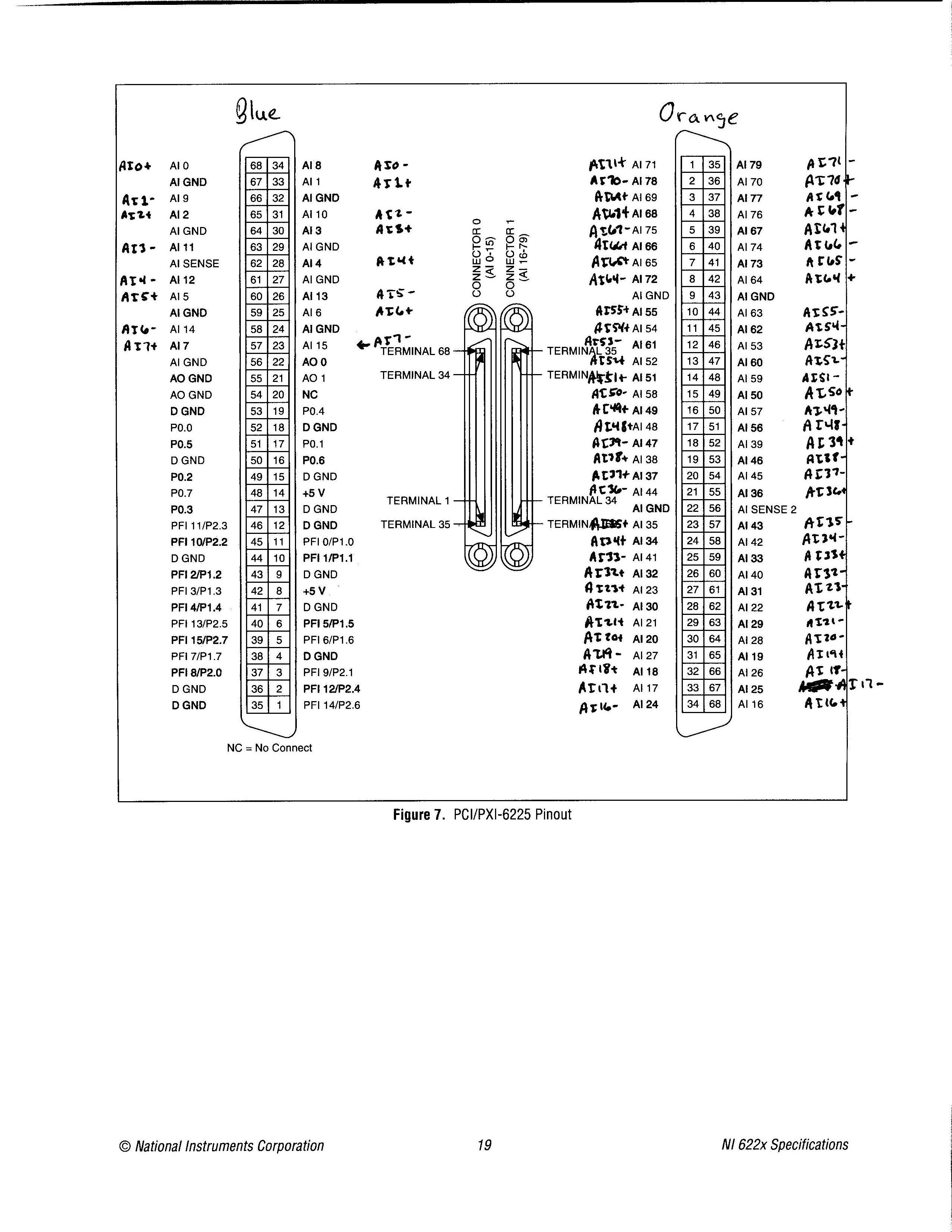
Pinout of the device from the PCI-6225 in differential Mode of I
Simple question: where is the pinout of the device for the card PCI-6225 for differential of analog input mode? I looked in the device list of the pins in MAX, in the NI 622 x specifications document and several other places, but I was not able to find it. I found the pinout for referenced asymmetrical measures, but no differential.
Related issue: most people use devices like the 6225 for no entries analog differential? So why in tarnation do many brand of material OR that upper and lower manuals, looking for the differential input version?
Thank you!
«Referring the number of pins would make it impossible to use the same code when you change maps DAQ.»
I'm not sure I followed here. Can you please explain a little further? Are you referring to the 1-68 0 connector pins and 1-68 pin connector 1? If so, I'm not sure, I followed. A different pinout may not change the code. If I had to replace a 6225 with another equivalent at least DAQmx device as many channels and the device number was the same, then I'd not change all the names of channel in the code, I? It would certainly change the wiring, which is precisely what I'm doing right now.
I know that the analog input channels look like ai0, ai1, etc.. My concern is later: where the jumps occur when you're in differential mode?
I have attached exactly what I would like to see in the documentation of ALL analog input device which allows the differential mode, only with the + and - channel names only and not the labels AI0-AI79. I couldn't find this photo any place, but rather had to laboriously calculate this pinout. If you know where to find this photo, I would be very grateful.
Thanks for the reply.
-
In differential Mode input impedance
Hi all
When I bought the USB-6212 card, I was impressed by the high input impedance of it - 10 GOhm.
This is indicated in the specifications, as in between HAVE + and AIGND.
So, what is the input under differential connection impedance?
Hi Navneet,
The question you have posted is actually a matter of multifunction data acquisition. You should post these questions in the Forums Multifunction DAQ. You will get much more quick answers to questions that are displayed in the correct forums.
The input impedance, in differential mode is a little less, then twice the impedance of the AI referenced to ground. What this means, is that he will be GOhms ~ 20 to 19. The actual value is not available, because it's such a high input impedance.
Best regards
Jonathan
-
Read a bit off in differential mode in NI 9205
I have an LVDT connected in differential mode in NI 9205 tends in NOR cDAQ 9172. The output signal full scale is from-10 to + 10 VDC VDC. The excitation voltage is +-15VDC. I placed the LVDT to read mVDC - 1400 on the digital multimeter (DMM), well, it oscillates between 1399 mVDC and mVDC-1400. When I read that in Labview 8.5, reading is about-1.410 VDC, oscillates between - 1.407 VDC and - 1.414 VDC. I know an offset of 10 mVDC isn't that much when my output full scale is 09:50 VDC and I'm not losing my sleep on. But I just wanted to know if it was normal.
The output LVDT signal is referenced (-terminal of excitement and - terminal of the output signal are linked, it is necessary) and I plugged this thread of land on the port COM of NI 9205.
I also have a sensor with floating floor whose output is 0-100 mVDC. I have it connected in differential mode too the + and - output terminals are connected to the ground/COM port using 100 k ohm bias registers. In this case, it is without lag at all. The DMM and Labview show the same reading. By the way I am at the same time by displaying the readings in Labview and DMM.
Hi sharmaa -.
You can find your shift error using pages 23 and 24 of the NI 9205 manual Instructions and specifications. 10 mV seems a bit high for this particular card, but as you say, 0.1% isn't so bad. I would say that you have the right not to lose sleep on.
Have a great weekend!
-
Problem: The differential mode, measure 1.4 V, USB-6009
Hello world
I am able to charge and discharge the two capacitors, individually.
I use the USB-6009;
Two capacitors, two charts, two analog inputs (AI0 +, AI01-) and (Al1 +, Ai1-);
I have configuredin differential mode; Ok
Problem:
When a capacitor is switched off, it measures 1.4 V
Try to correctly set the task - run the DAQ Assistant to create the task

Dev1/ao0 would be much better - Oh, and now that you take the wizard open-Do on the wiring diagram, it offers you

For the PREMIUM of 6009 task mode AI0 is + AI3 is - and you only reserve reserve explicitly AI0 (AI3 line is reserved by seleting the + line in the channel and the declairing it is differentiated)
And give the task/channel a significant name of "MyCap1Discharge" would be useful...
Now let's talk about your electrical engineering:
The input of the 6009 impedance is 144kOhms the resistance of discharge 1MOhm becomes useless as soon as you connect the control AI 6009.
-
Using a FP-I-V5 in differential mode
Hello
I'm creating an application by using the Modules of Point field. I use some memory twin for i/o modules. Does anyone know how we should connect module FP-I-V5 channel as differential. Examples of the operating instructions do not cover the case of differential.
Any help would be appreciated.
Hello
Dual Channel FieldPoint modules are isolated from each other. For analog modules, such as the FP HAVE V5, the two channels on the module share the same commune, while they are considered to be asymmetric. However, if you only use one channel, you don't share in common with the other channels and are therefore the differential measure.
To use the FP-I-V5 as a differential module, simply use a single channel.
Kind regards
Green shores
Support Engineer produces FieldPoint
National Instruments -
How to set the differential input for personal iotech Daq/3000 mode
Hi all
I currently use personal iotech daq/3000 for the acquisition of data from the accelerometer.
I got readings of the analog input, while there seems to be no configuration for the differential mode.
What I have is:
selection of material - personaldaq / 3000:direct
Double click on, then:
Channel installation, there should be a selection of differential mode, I guess. But this is not.
Thank you very much
Alan
Have you reviewed the C:\Program Files\DASYLab 10.0\manuals\IOtech_DAQ_notes. PDF? Or the help of equipment?
The section of material assistance, using the analog inputs with DASYLab, includes pictures to show how to do this.
Open hardware driver.
Click the line Analog Input Channels, and then right-click to open the properties. This will display a dialog box that allows you to set the properties.
-
Differential measurement across the ground of the card NOR referenced output.
Hello guys,.
I have a question, our pure curiosity.
I use map of USB6212 to apply a sinusoidal signal of 10V to a game to the top, then measure the tension between charges.
I'm attching here a simple diagram showing the system. The implementation can be modeled as a combination of RC - r series
Note that I'm also measure voltage R2 in differential mode. Now that I am after is exact phase of monitoring between the two voltages (according to the RC and the R2).
My question: is the correct diagram? I mean - is it OK to measure the voltage across R2 in differential mode with attached as such polarization resistors?
It is one of the lines through R2 is already at AOGND. And AIGND and AOGNd are already connected inside the card, it will be then introduced errors?
or does not at all?
Thanks guys, will be grateful for a quick solution.
You can do this but the differential mode does not have much. Your signal source is single ended. The voltage at the terminals of R1 - C can be measured in different ways. It really is meaningless to measure the voltage across R2 differently because one end is connected to the Earth. Polarization resistance, Rb, are not necessary in this case because the low enough impedance DC railways exist at all entrances.
What I would do, is make two measures ended up alone. AO1 measured on a single channel (AI0). Measure the R1 - R2 junction on the other channel (AI1). Then the input voltage is AI0, the voltage at the terminals of R1 - C is AI0 - AI1, and the current is AI1/R2. You will need to enjoy fast enough that the time between the different measures does not contribute too much to the phase error. It depends on your frequency of signal and eligible errors. Look at the charts of a waiting time to page 2 of the NI USB - 620 x specifications for more information on how to compromise between the speed, accuracy and multichannel source on measures resistance.
Lynn
-
NI 9205 analog incorrect values in multichannel mode
Hello everyone
I am actually measuring 10 battery cell voltages (which are connected in series) with a NI 9205 (slot 1) in a frame NOR cDAQ-9172.
The voltage of each cell is measured in differential mode with channels 0 through 7, 16 and 17. I have no connection to the NI 9205 COM Terminal.
The other modules in the chassis are NI 9217 (2 modules, slot 2 and 3), NI 9481 (4 locations) and NI 9401 (5 location).
In my LabView program, I put all the channels of the NI 9205 and NI 9217 modules in a single task, because a single task can function both for the measurement of analog input.
My problem is that some of the values measured by the module NOR 9205 do not correspond to reality. All of the tensions 10 cells is about 2.60 V (measured with DMM). But, for example, channel 2 shows 2.67. Some channels are right and others are not.
I tried to vary the frequency of sampling, but this does not really solve the problem.
For example:
Sample rate = 1000-online channel 2 = 2.72 V
Sample rate = 100-online channel 2 = 2.67 V
Sample rate = 10-online channel 2 = 2.67 V
Then I tried to put all strings in a single task and allow a task after another. And then it worked!
But data acquisition is so slow, when you create a single task for each channel and that's why I prefer the way with several channels in a single task.
I don't know if my wiring should consider all connections to the Earth!
Thanks for any help!
Concerning
Socki
Hey Patrick
Your index really helped out me of a jam.
I had to reduce the frequency of clock to convert my module to HAVE. Now, it works great!
Sampling rate is 20 and convert clock frequency is 200 (for 10 channels)
The vi from the following link shows how to change clock frequency convert it (Set convert Clock.vi):
http://digital.NI.com/public.nsf/WebSearch/42484E84DA98053686256D32006E0494?OpenDocument
For my module, I had also to choose and connect the "active devices" on the property node DAQmx-Timing.
Thank you!!
Concerning
Socki
-
With differential measurement noise problems
Hey everybody.
I use an NI USB-6211, LABView 2011 and Win7.
I'm trying to measure a voltage through a resistor using differential mode. But unfortunately im getting a lot of noise (on + - 25%).
The voltage source I use is variable and can go up to 600V. With my diet I am essentially heat a metal plate.
A parallel voltage divider is used to reduce the voltage by one hundredth (1 MOhm and 10 kOhm).
Two wires attached to the lower resistance then go directly into analog input 0 + 8 of data acquisition.
So if I'm trained 600V to the plate, data acquisition should get about 6V... and that's what I measure with my voltmeter attached to the acquisition of data input pins.
I also tried these resistances of POLARIZATION and connected the + and - leads to the analogous to the ground like a resistance I used 10 k, 100 k and 1 MOhm and 2 MOhm and
continue to receive a bad signal.
Two sketches of the wire as a signal (100V, supposed to measure 1V, no CORRECTION) are attached to the post.
Concerning
EDIT: I forgot to write that I even tried an another NI DAQ and still get this noise problem.
Also, I measured the voltage source signal using an oscilloscope and I see that noise. But the differential mode isn't supposed to
reduce noise to a minimum?
Hey everybody,
come to understand that the voltage divider resistors are medium to high and they were the main reason for the noise
problem.
Before I used 1 MOhm and 10 kOhm, now I use 100 ohm and 100 kOhm and with a median filter in this regard, it works very well!
But still, if I use the resistance of these BIASES they do not change.
Concerning
-
How to set programmatically for differential thermocouple?
I'm trying to understand how a physical differential 'channel' (really a pair of channels) gets from a virtual channel. Specifically, I'm gaining of a thermocouple (K) using a differential connection.
In AIChannels.CreateAccelerometerChannel, for example, you can specify whether you want to create a differentiated channel. In the NOR-DAQmx help file, I see that for the M series (which I have), the differential negative physical channel number is 8 + the positive number. And he says "pass only the name of the positive channel" to the function create the differential [virtual] channel.
In AIChannels.CreateThermocoupleChannel there is no option to specify differential, single ended, etc. It is therefore impossible to use CreateThermocoupleChannel and connect the thermocouple to differential mode? In other words, do I have to create a channel of tension and then make the temperature conversion myself?
Hi pelesl.
Most of the parameters for methods of creating DAQmx channel is used to set properties on the newly created channels. You can also get or set the same properties yourself. The terminal configuration parameter in the method of creating channels voltage corresponds to the TerminalConfiguration property, so you should be able to do something like this:
AIChannel chan = task. AIChannels.CreateThermocoupleChannel (...);
Chan. TerminalConfiguration = AITerminalConfiguration.Differential;
Brad
-
Measure the pressure with NI9205 in Mode CSR
I use the NI9205 module to measure the pressure, but when I connect two transducers of pressure for the module in the CSR mode there is a decrease of output signal of the pressure sensor and when I dissconnect it the signal to return to the previous value, also when I use the differential mode after a few seconds the output signal turns into a 50 Hz oscillation , can you help me please?
the pressure transducers are PDCR 4011, output 200mV and must provide of 10V and I use two similar power supply for transducers.
Thank you
Omid
Hello Omid,
It doesn't sound like the shields were inducing 50 Hz noise that you saw. They might have been picking up some other equipment in the room, and I think that Earth shield is the right solution for the problem.
Best regards
Adam G
-
I want to use the usb-6225 (screw terminals) in differential mode, but I can't find the pinout. Can you help me? Thank you
Here is a link to the specification. The list of the pins are at the end.
http://sine.NI.com/DS/app/doc/p/ID/DS-10/lang/en
In differential mode, it works in groups of 16. A0 is the + and A8 is-, A1 + and A9 - etc. A16 is + and A24 - etc.
-
6225 DAQmx names for measurements of the differential pair
All,
I came across this post trying to find out if there was documentation to show who's analog inputs are coupled together and what name DAQmx controls call these pairs.
Messages from the author a drawing which I think is correct, but it is not an official document of OR. I'm looking for documents that says exactly what the name is for each pair during their use in a command DAQmx. I know literature 6225 AI0 and AI8 form a pair, and AI1 and AI9 are a pair, etc. etc. What I was trying to find, is documentation that shows that the name of each of these pairs, what I should do in the DAQmx calls during a differential measure. Currently, I am assuming that the AI0/AI8 pair is referred to as AI0 when the measure differential. I have just followed the list of pairs in the manual of the user from left to right and from top to bottom and naming of AI0 to AI39. I really was hoping that there was an official document that says what were the names of each differential pair.
Can you point me to the appropriate document or tell me that it is not an and that my assumptions are correct?
Thank you!
Doug
Doug,
There is not an official document similar to the one in the related post that shows the AI0 + and AI0-. The differential channel will always be referred to by the positive terminal. It doesn't matter what differential channel number it is. For example, the Channel 9 differential uses AI16 as the positive terminal. All configurations in DAQmx must be configured using AI16 in differential mode. The drawing was published is not official, but it is correct.
Kind regards
Danny F
-
measures 16 differential signals
Greetings from the Argentina!, I use an NI USB-6218 box for measure 16 analog floating aboutthose, in differential mode. I have a practical problem, to avoid erratic results, I have to use 2 resistors of polarization to THE GND for each signal, which means that I need 32 resistance!, we chose this ADQ unit because we need a system compact adq but use all this if resistances not practical at all. You have a more simple solution?, is there any accessory sources which includes resistors to GND?
Thank you and excuse my English...
a bit of these will keep it nice and tidy
Maybe you are looking for
-
Mail is deleted from the iMac when removing the iPhone
When I delete messages from my iPhone, they are also deleted my mail on my iMac, but it does not appear the opposite effect. When I remove it from my iMac, they remain in the phone so that they accumulate a lot a lot of emails. Is it the way it is
-
Photosmart C4780: HP Photosmart C4780 Firmware Update Fail
I downloaded the updated of the "C4700_FWUpdate_4362_HPCOM_v1" firmware, but every time I try to install the wizard says that my printer is not connected. In fact, it is connected by USB cable and wireless. I can print to it, printing and scanning
-
Series Edge (E) internal second hard drive
I was wondering if users of portable Edge series or E are using / used a second internal drive? Officially, their sales staff, in this series of laptops feature to replace the optical drive with a hard disk has been removed. Their tech staff said whe
-
Is there a way to remotely run the process of initial configuration on a fabric to interconnect via SSH without erasing the config?
-
Copy and paste not working only not on a new installation of Windows 7.
Hello My copy and pasting worked very well after that installation, and all of a sudden, it stopped working. I have no change at all. Just work away suddenly stopped. Windows 7 is less then 24 hours on my laptop, and I've already found a problem :-(