PtbyPt filter FIR in the Loop Simulation
Hello
Currently, I am trying to simulate the power in my engine when I apply a voltage step for 20 MS for that I intend to use a FIR filter in the control and simulation module that simulates the other parts of the engine.
However, I have found that the FIR filter seems to be strange behavior. When I change the order of Runge-Kutta 1 simulation to 2 of Runge-Kutta it effects the output of the filter FIR PtbyPt VI. The two attached images show how the results of the convolution of the IR and the tension, the FIR outside the simulation loop filter and FIR filter in a loop using Runge-Kutta 1 are the same. However, the second image shows that the FIR filter in the loop simulation Runge-Kutta 2, has a different answer.
Why does this happen? As I understand it, the type of simulation should have little effect on the application of a FIR filter based on pt by pt. I have not changed the timestep or other parts of the simulation. I want to use a simulation of order higher than for other parts of Runge-Kutta 1 would be insufficient for the simulation.
I'm using LabVIEW 2011 SP1.
Thank you
Rhys
When you try to use RK-2 or higher order, the screw that dumped you inside the control and the Simulation loop, by default, they will all run in the "minor" time steps too. In your case, 'two times' which means the VI will be executed each time step.
To properly configure these screws, you must "right click" on the VI and select "Installation of the Sub - VI node. This will bring to a Setup page that the second half you will choose in 'Type of Simulation Subvi execution' to 'remove' the "Include minor steps" box and press OK. When you do this, the Sub - VI will be annotated on the upper right with blue 'C' and when you run, it should provide a similar result as RK-1.
Note that in this dialog box, you can also select discreet, which, in many cases, it is the right selection for 'discrete' systems
I hope this helps...
Tags: NI Software
Similar Questions
-
Simulation does not stop in the Loop Simulation & control
I'm working on a settlement in a loop of control & Simulation. I created a State space model and an inside observer.
Now, I've implemented nearlly all, but now the simulation does not stop.
First here is a picture of the .vi when it still works:
But this isn't the end result, I want to have.
I want to connect the output of the subtrahation (2 x - y) at the entrance to the exterior product.
You can see from the image below:
If I do, my continious simulation and never stops. The simulation time is always set to 10 sec.
The .vi is attached. I hope someone can help me.
I don't understand your suggestion. I've set up a node of your comments, but this does not solve the problem.
But I found another solution to the problem. I build the .vi completely new and used the arithmetic of the design group Signal and control Simulation. The gain block and the summation block works better in my case that digital add and multiply the blocks. Now, the tracks of the simulation and the regulation works well.
-
Increase control of the façade of a trigger button in the Loop Simulation
I want the 'Index' control to automatically increment when you press the OK button. It works very well. However, the control of the Index gets automatically incremented whenever the VI is started and when you press the Stop button. Even if the box Structure is wired with a constant False (which means that it must never be run), control of the Index is still incremented.
Is there a bug when using local variables within the structures of the case in the Simulation loop? This does not occur when you use a while loop.
I think that since a loop of Simulation has no shift registers, you will need to use a feedback node.
I have NO experience using simulation loops, just trying to help.

See the example attached to see what I mean.
-
Function of memory in the loop control and Simulation - problem of the ODE Solver
Hello
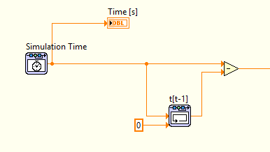
I'm correctly using the control loop & simulation to simulate the behavior of what is essentially a shock absorber-spring-mass system. In the process of change in time (dt) is used to integrate an arbitrary value. I use a rack depending on memory to store the time, to calculate the change of time (dt).
The simulation is quite complex, because of the precision required, not all the ODE solvers can all support. Currently I use the Adams-Moulton method, this works very well for the simulation. However, it cannot detect the change in time, the change is constantly zero. This problem has auto market by using an another ODE Solver, but then the simulation has been messed up instead (even when I listen to the step sizes and tolerances). So I'm pretty confident that Adams-Moulton is one of solver ODE best suited to the problem at hand.
Is there another way to store the previous hour and use it calculate lag, that the use of the memory function? Everyone knows about these problems before?
I did a lot of research of error using the probe, but I'm sure that there is a problem with the ODE Solver and memory function. See the image below, showing basic how is calculated the change in time.
I'm pretty new to LabVIEW, so if there is something else I missed I would be happy to hear it.
PS! I set the tolerance minimum step of size/relative and absolute for the Adams-Moulton to simulate the behavior of the system properly.
Problem solved!
It turns out that the ODE Solver has struggled because of two "table 2D find" used functions. This was created for the interpolation/extrapolation, which caused a problem constantly and the ODE Solver could not resolve correctly, so the functions of memory doesn't work does not correctly or the other.
By increasing the table manually, I could use closest method instead, with also good results as interpolation.
-
How to create a delay between the start of the signal simulated one and the other?
Hello
As a first step, I am relatively new to Labview.
I am trying to use Labview for 2 different output square waves (different frequencies, amplitudes, etc.). I've implemented 2 signals to simulate different and do them in a While loop, however, when I start the program, I need a square to begin signal immediately and the other to start square waves 2 seconds later. Any help would be greatly appreciated.
Thank you!
A few questions.
Are these frequencies of associated signals? If so, were they to be "in phase"? As from one simulation after another, put one start later in a case statement, pass a county of timer to establish the initial start time through the loop, subtract the value of the other in the loop, when the difference is => in 2 seconds, set a real flag and have the second simulation in the real of the structure of the business case.
Typed too slowly again!
-
Then as the loop timer Timing vannes_ouvertes. Elements
I would like this while loop to iterate through every second. But it seems that he doesen't recognize the loop timer. What's wrong?
Just found the article to help talking about it: Debugging of FPGA screws using Mode Simulation (FPGA Module)
At the bottom, it says:
Understanding simulated time on the host computer
If you use some FPGA resources and you run the FPGA VI in simulated using I/O simulation mode, the resource uses simulated time rather than real time. Simulated time could be faster than real time according to the number of events that occur during the simulation. For example, if you add a waiting VI (simulated time) for the schema and set the timeout to 1000 ms, LabVIEW does not attempt to delay a second of real time. Instead, LabVIEW delays as long as necessary before performing the next action scheduled in the simulation.
The following resources are using the simulated time on the host:
- Then the loops
- Single-Cycle timed loops
- VI of waiting (simulated time)
- Loop timer Express VI
- Number of cycles Express VI
- FIFO, except DMA FIFO
- Wait on Occurrence with Timeout based on ticks
- Interrupt the VI, during her wait until this that clear is TRUE
-
Savitzky-Golay smoothing filter FIR
Which version has the FIR Savitzky-Golay smoothing filter?
Professional or business?
Mario
Hi Mario,.
The FIR Savitzky-Golay smoothing filter is in the Professional and Enterprise.
Information on what is and is not included is located on the link below:
http://www.NI.com/analysis/cwtools_analysis.htm
I also checked using Professional editions and Enterprise functions exist in two versions of assemblies Analysis.
-
I'm trying to filter the 120htz of certain data. I thought just use a simple FIR filter and chop the 110 to 130 Htz band. I don't know much about the FIR filters however I'm not trying to do anything particularly complicated. The problem is that I don't seem to know what PB and SB are. I read thought the forums and they seem to only repeat what help... implies that higher SB is highest between the two frequencies of stopband and lower SB is the lesser of the two stopband frequencies. But this doesn't seem to be the case... or I don't understand what is happening.
If I am using a bandstop filter, I should ONLY need Upper and Lower SB to define. For my 110 application should be the lower SB and 130 superior SB... but it does not work. So obviously, this VI is not what I think it does. Can someone help or direct me twards and example? Or y at - it an easier way of fliter on a frequency band of narorw from a set of data?
And yes I know it's a LOT of noise 120htz. I can slightly reduce. This has been intentionally increased if I could play with the bandstop filter. Also I use the latest version of labview... student and do not have the possibility to buy the filter SDK.
Kevin
Kevin,
1. the very large shift in the numbers on your graph (1.8E8) is part of the problem. Remove this and you can get a filter.
2. the topology should be something other than the default (Off). The default value is not filtering.
3. because the function decomposition (is that what you want?) has the components of frequency in the same range as your intervention, no filter will remove all components of 120 Hz.
4. the transient filter can prevent you from getting a lot of information on the first part of your signal.
5. While the sampling rate satisfies the Nyquist criterion, you have only about 8 useful Samper by cycle of the 120 Hz signal. A higher sampling rate might give you more data to work with.
Can you tell us more about the real problem? What is the nature of the desired signal? Is the stable 120 Hz interference or a source that can be controlled independently the desired signal?
Lynn
-
Subvi in the memory of the loop
Hello
I have a loop that contains 3 subVIs that are exactly the same (that's why I use a Subvi
 ) each Subvi controls a device (again 3 devices that are the same). The entries to each Subvi is from a Mathscript node. Thus, on each iteration of the loop (1 s), the output of the Mathscript node will be introduced in the subVIs.
The problem is that one of the 3 devices (the same one every time) gives an error after running for a few seconds. The error usually occurs because that the device does not receive an acknowledgment message after 3 seconds of running. I renamed the Subvi that controls this device, without changing the code and everything seems to work normally. Now, since the subVIs are all the same, I swapped two of them (one that I have renamed and another) and series of programs without problem.
I don't know how labview treats same subVIs inside loops, and that's what I want to know. Even if the output of the Mathscript node occur at the same time (after performance of all knots), and therefore the entry of the subVIs are all ready at the same time, the SubVIs seems to launch successively, or at least not instantly.
The device that fires an error is the first to run, and knowing that the Subvi contains a timeout 2000 ms, this device does not receive the recognition after 3s (because the acknowledgement is sent to the next iteration of the loop, if the subVIs 3 should go first before the iteration of the loop). That is, I changed the Subvi to decrease its 1710 ms delay time and use the same Subvi for 3 machines (without renaming it useless) and the program works flawlessly again.
So, I'm just curious how Labview deal of same subvis that simultaneously run inside a loop.
Thank you
I agree with Ben.
Mark your sub - VI as re-entering to allow all three instance of the same VI to run at the same time.
Default VI is marked as non-reentrant so they in turn running sub - VI.
In my Action Engine nugget , I have included this image to illustrate how multiple calls to a VI which is not reentrant is shared between instances.

If you don't want to make the screws under reentrant you might also do a save as... and use three identicle VI which differ only in name. I generally avoid this approach because the code for the sub - VI changes require that change all versions. Better to bite the bullet and learn how to set the VI as re-entering.
I hope this helps,
Ben
# 10 000
-
Model in the loop timed While the elapsed time
Hello NOR community,
I'm trying to use a while loop timed to run controller simulated for a mechanical system test. I need the time loop to run at an even 50 Hz to simulate the controller that will eventually drive the mechanical system. To check the speed at which the loop runs, I made a VI that gets a value from each loop clock and subtracts the value of the clock of the current iteration of the value of the clock of the previous iteration. I have eliminated all other codes this VI except for the recovery of the clock, to ensure that no problem with another code in VI. I find that the time between iterations is not constant, but it is consistent. In other words, the elapsed time can change at each loop, but it changes according to a specific model, such that the average elapsed time is equal to the value that I use for the timed loop. The loop will run faster than posed for several cycles, then slow down during a cycle even at the same time. Here are some examples:
Running at 5 Hz: elapsed switches schedules between 0.203125 and 0,187500 seconds
Clocked at 8 Hz: time is constantly 0.125 seconds.
Operating at 10 Hz: elapsed switches schedules between 0,109375 and 0,093750 seconds
By examining the differences between elapsed time and the stability of the 8 Hz setting, it seems that there is a minimum time of 0,015625 seconds (64 Hz) division. It is much worse than the 1ms accuracy claimed in documentation. This could be the cause?
I am running Windows XP with LabVIEW version 8.5.1 and have observed this behavior on several computers with different screws
Thank you!
Erik
Your problem is the function that you use to get the current time. It's just the time of the Windows clock which has a resolution of 16 msec.
You must use the function of number of cycles as Jarle has pointed out.
-
SR400 while the loop does not work
Hello
I'm using LabVIEW for control SR400 through a GPIB card.
I use SR400 to count the number of signal in a second, wait 0.05 s, then again count the signal once, wait 0.05 s once again, and so on.
However, the while loop didn't iterate. When I started the program, it is only once.
In execution of highlight mode, when an iteration is finished, he waited a long period starting the next. In normal mode, it doesn't have to iterate.
Also when I clicked the stop button, it's been clicked. However when I wrote a very simple program, the stop button worked normally.
In any case the button issue is not very important. I don't care that the program iterates forever or not. I just want to iterate.
I searched the jury and had not could not any related problem.
Is it better to attach my VI? The VI is in my computer lab.
Thank you very much!
This code just feels bad.

(No real management mistakes, deep, stacked sequences FOR lines that are wired to iterate through only once, controls on the right and right to left, wiring weird code on average the last 10 items (Hint: means ptbypt with a length of 10 sample he would!).) If you want to use the wire of the error, the sequences would not even necessary)
If the stop button does not reset, it means that the iteration of the loop does not terminate. It can fill in only if the two structures of the sequence ends.
Have you tried running in execution, emphasizing fashion while looking at the diagram? Probably one of the communications is at a standstill. For example, the instrument sends really 6 bytes at the end? When you set the overall timeout and what is it?
-
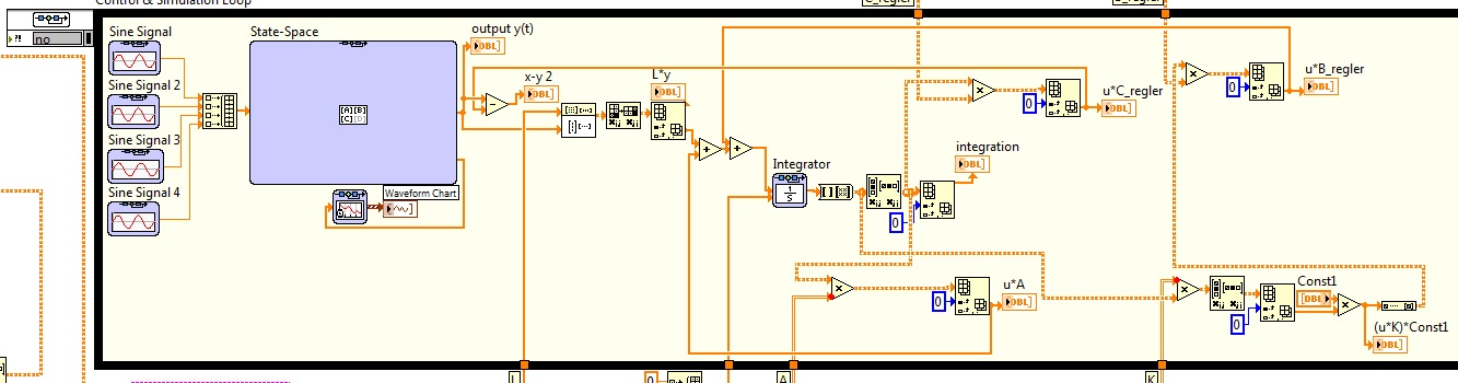
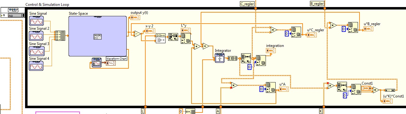
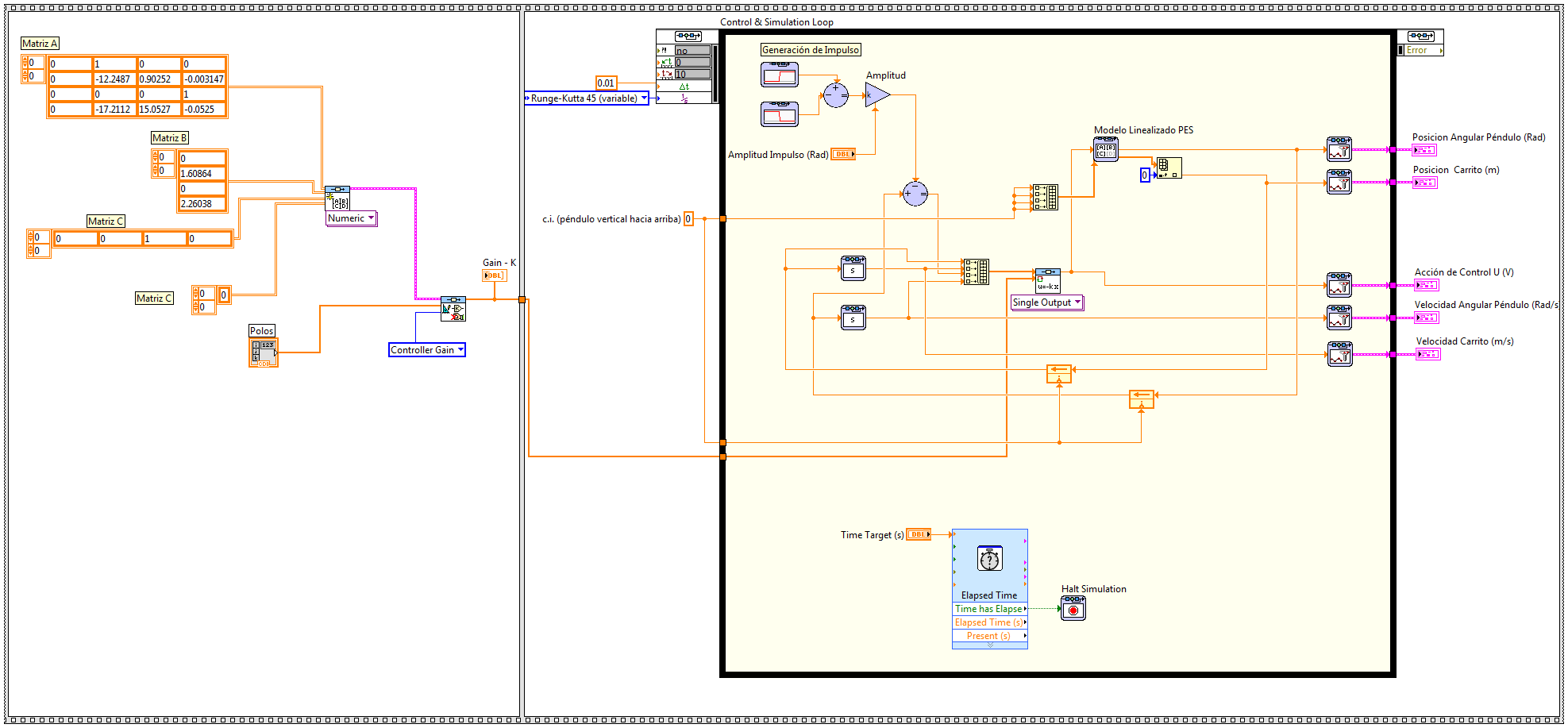
I wonder if there is someone who could give me a helping hand with a simulation, that I'm running. I am trying to simulate the behavior of a system modeled as state space and do a controller using different techniques, but I'm having problems and can't advance too far... It seems that the simulation loop gets on a sort of infinite loop and he can't stop but I don't know what else to do... Left, I enclose the block diagram of one of the screws simulation I so could someone there watching.
It is a model of an inverted pendulum system and a cart modeled as state space and try to see the behavior of a placement of pole due to a pulse controller imput. Initially, I would check a model no length I have but it was too weird so I replaced it with the linear model to the point of unstable equilibrium, but the VI stuck too then I felt motivated to post here.
(I tried to join the extract by using the code below, image generatin capture tool so you can download and run the code, but it's my first time using this tool, so hopefully it will work well... I created the extract .png and gasket here using insert image... that is right? )
In the Simulation node, shift registers could have different behavior which would explain the problem that you run in. So, if you want to 'break' the feedback node (which in general, you shouldn't need to do), then use the block of 'memory '. He'll try to behave as you would expect.
In addition, you can look at the example of shipment for the linear simulation:
C:\Program Files (x 86) \National Instruments\LabVIEW 2014\examples\Control and Simulation\Case Studies\Mechatronics\Inverted Pendulum\Linear inverted pendulum Simulation.vi
Or non-linear simulation:
C:\Program Files (x 86) \National Instruments\LabVIEW 2014\examples\Control and Simulation\Case Studies\Mechatronics\Cart-Pole\CDEx Cart-pole control and Simulation.vi
as a reference for your example. You notice even reuse the animation for your application.
-
How to cause a loop to move to the next item in the loop?
How to cause a loop to move to the next item in the loop? cfbreak leaves whole loop I want
< cfloop condition = 'i' less THAN or EQUAL to #ArrayLen (arrData) # >
<!-we need filter so the uplaod problem lines does not crash '->
< cfif not REFind ("^ [0-2] [0-9] [/] [0-1] [0-2] [/] [1-2] [0-9]" {3} $", arrData [i] [1]") > <! - treat date - >
loop jump the agenda (IE i ++)
< / cfif >Thank you
does not the loop move on to the next item in the loop, it mearly incraments var I. is actually the loop switch the order of the day. It's inevitable, because I is the loop index. In any case, as others have suggested, you can skip the history quite i. Just follow your instinct and code it directly as you feel.
I want to check each line but if there is a mistake in any column in the same row I want to ignore the whole line
-
Thunderbird is stuck in the loop. Can not stop in the Task Manager.
links will not open in thunderbird. I followed the instructions in this link: http://www.ghacks.net/2013/01/20/fix-for-thunderbird-not-opening-links/.
After you set the 3 True values, I left and restarted thunderbird.
I then clicked on a link in an e-mail message and the LAUNCH APPLICATION box appeared.
I accidentally entered "thunderbird" instead of "firefox".
When I clicked on the link in the e-mail, it goes into a loop where the hourglass icon will flash constantly.
I couldn't go back to the LAUNCH APPLICATION window to change.
Then, I deleted the Thunderbird folder in program files and reinstalled thunderbird OK.
Everything works fine until I click on a link in a message. He then goes into the loop, and I have to restart.
Is there something in the registry that I can change to fix this?
Thanks for any help you can offer.
Kind regards
Geoff WightGo to the menu Tools (alt + T) > options > attachments and delete any reference to Thunderbird.
Change the preferences to their default values. by https://support.mozilla.org/en-US/kb/Hyperlinks-in-Messages-Not-Working#w_check-for-an-incorrect-preference then you can read any article that the incorrect pref is usually only a question after using the Thunderbrowse add-on.
-
Have checked tutorials and help , but doesn't understand why hovering over the right angle, at the top of the track loop not give me the slider that allows me to draw on the track and extend the playback loop.
Long kickflip is the one that gives me a problem right now, but Latin Bembe Cowbell does not work for me either!
It is my first try at GarageBand, and maybe my last very soon. Thanks for easy to understand help you send.
The two loops work very well for me in GarageBand 10.1.1. Skip on the upper right corner of the audio region to display the cursor of the loop, if it is not, save your project and the test in a different project. Restart your Mac, if you don't have already done.


Maybe you are looking for
-
How uninstall Firefox when it always says that it is running
I checked all the troubleshooting suggestions to get Firefox running properly again. Finally decided that I just need to completely remove and download a new copy. Problem is when I try to uninstall the program he says "Firefox must be closed for uni
-
I was downloading 300 messages using GET MAIL and he won after 200 messages. Thereafter, every time I hit GET MAIL it says it downloads 1 of 130 (or more) messages and then quickly shuts down indicating "no message to download. The last message it do
-
How to delete messages in my "Outbox" Windowsmail - he keeps their removal?
My "Outbox" Windowsmail guard reference 5 messages and I can't find any way to remove or empty the 'Outbox.
-
Seriously, I made the leap to one of these routers and bought computers Canada on Rideau in Ottawa Street, I had not a ca connection again... was running on N only... still a lot of drops and regular connection problems... Now I buy a usb adabpter CA
-
How blackBerry Smartphones entry Contact Zip Code default to Numeric rather than Alphabetic?
In addition to coding in whenever I want to enter a zip code digital for a new contact (99.9% of my contact postcodes are purely digital), is there a configuration option by default to communicate with Postal Codes in Numeric rather than Alphabetic.