Savitzky-Golay smoothing filter FIR
Which version has the FIR Savitzky-Golay smoothing filter?
Professional or business?
Mario
Hi Mario,.
The FIR Savitzky-Golay smoothing filter is in the Professional and Enterprise.
Information on what is and is not included is located on the link below:
http://www.NI.com/analysis/cwtools_analysis.htm
I also checked using Professional editions and Enterprise functions exist in two versions of assemblies Analysis.
Tags: NI Software
Similar Questions
-
PtbyPt filter FIR in the Loop Simulation
Hello
Currently, I am trying to simulate the power in my engine when I apply a voltage step for 20 MS for that I intend to use a FIR filter in the control and simulation module that simulates the other parts of the engine.
However, I have found that the FIR filter seems to be strange behavior. When I change the order of Runge-Kutta 1 simulation to 2 of Runge-Kutta it effects the output of the filter FIR PtbyPt VI. The two attached images show how the results of the convolution of the IR and the tension, the FIR outside the simulation loop filter and FIR filter in a loop using Runge-Kutta 1 are the same. However, the second image shows that the FIR filter in the loop simulation Runge-Kutta 2, has a different answer.
Why does this happen? As I understand it, the type of simulation should have little effect on the application of a FIR filter based on pt by pt. I have not changed the timestep or other parts of the simulation. I want to use a simulation of order higher than for other parts of Runge-Kutta 1 would be insufficient for the simulation.
I'm using LabVIEW 2011 SP1.
Thank you
Rhys
When you try to use RK-2 or higher order, the screw that dumped you inside the control and the Simulation loop, by default, they will all run in the "minor" time steps too. In your case, 'two times' which means the VI will be executed each time step.
To properly configure these screws, you must "right click" on the VI and select "Installation of the Sub - VI node. This will bring to a Setup page that the second half you will choose in 'Type of Simulation Subvi execution' to 'remove' the "Include minor steps" box and press OK. When you do this, the Sub - VI will be annotated on the upper right with blue 'C' and when you run, it should provide a similar result as RK-1.
Note that in this dialog box, you can also select discreet, which, in many cases, it is the right selection for 'discrete' systems
I hope this helps...
-
I'm trying to filter the 120htz of certain data. I thought just use a simple FIR filter and chop the 110 to 130 Htz band. I don't know much about the FIR filters however I'm not trying to do anything particularly complicated. The problem is that I don't seem to know what PB and SB are. I read thought the forums and they seem to only repeat what help... implies that higher SB is highest between the two frequencies of stopband and lower SB is the lesser of the two stopband frequencies. But this doesn't seem to be the case... or I don't understand what is happening.
If I am using a bandstop filter, I should ONLY need Upper and Lower SB to define. For my 110 application should be the lower SB and 130 superior SB... but it does not work. So obviously, this VI is not what I think it does. Can someone help or direct me twards and example? Or y at - it an easier way of fliter on a frequency band of narorw from a set of data?
And yes I know it's a LOT of noise 120htz. I can slightly reduce. This has been intentionally increased if I could play with the bandstop filter. Also I use the latest version of labview... student and do not have the possibility to buy the filter SDK.
Kevin
Kevin,
1. the very large shift in the numbers on your graph (1.8E8) is part of the problem. Remove this and you can get a filter.
2. the topology should be something other than the default (Off). The default value is not filtering.
3. because the function decomposition (is that what you want?) has the components of frequency in the same range as your intervention, no filter will remove all components of 120 Hz.
4. the transient filter can prevent you from getting a lot of information on the first part of your signal.
5. While the sampling rate satisfies the Nyquist criterion, you have only about 8 useful Samper by cycle of the 120 Hz signal. A higher sampling rate might give you more data to work with.
Can you tell us more about the real problem? What is the nature of the desired signal? Is the stable 120 Hz interference or a source that can be controlled independently the desired signal?
Lynn
-
How smooth a XY chart by using Labview 6i?
Hello
My main Vi captures the data that I sent to a XY graph
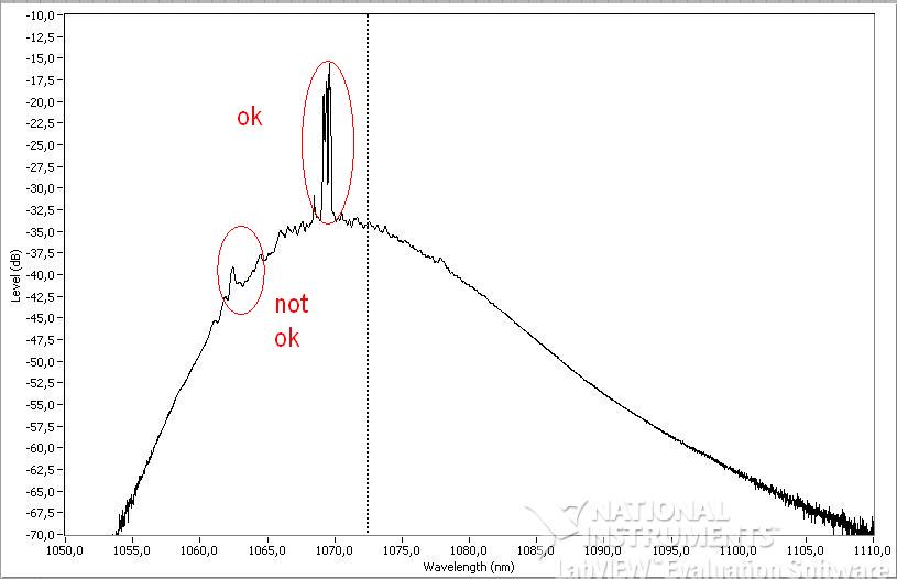
I would like to smooth out the curve before and after ('not ok' on the photo) the main peak ('ok' on the photo)
I looked for aboard or and have not found anything that I could use with Labview 6i
Does anyone have a solution?
Thanks in advance
See attached simple vi with data and graphics
There are several options:
- Use the filters in the range of Signal Processing to smooth the data.
- Fourier filtering techniques to smooth the data. Fourier transformations are also in the range of Signal Processing.
- Use almost any technical standard smoothing. To view the online version of the Numerical Recipes many methods. You will need C in LabVIEW, but it's pretty easy. Savitzky-Golay smoothing is especially good for this type of problem.
You will need to convert your XY data to waveform to get one of these at work. If you data are spaced regularly, it's pretty easy. If they are not, you will need to make some kind of interpolation. Or you can simply ignore the fact that you have unevenly sampled data, convert a waveform, smooth, then convert back.
A word of warning. The 'not OK' part of your waveform seems to have important characteristics. Putting my hat physicist for a moment, are you sure you want these pics gone? This is also true of the myriad of small peaks around the main one. Be careful. A better approach might be to eliminate differences in gain in order to have a flat bottom (1060nm region - 1080nm), and then try to model the peaks of interest. You could also take multiple series of data and to get rid of some of your sounds, average your X-scale condition is stable. But it really seems not to be much noise on these data. Most seem to be important.
-
Hey guys,.
I the DFD Toolbox and already built a few low pass FIR filter. I have a sampling rate of 50 kHz and I decimate it with a CIC filter with rate variable decimation. After the CIC filter, I need a high-grab for the low-pass filter FIR because I do want my DC signal. As I can change my rate of decimation, my FIR filter sampling rate changes also.
The problem is that the coefficients of the filter cannot be changed during execution as the Butterworth IIR-filter function, including labview has implemented in the mathematics of the fpga function palette section.
Are there examples how to build FIR filters where I can change the coefficients on the run?
Think you can build a low pass FIR with the DFD toolkit and simply change the table with the coef. for a control? I could change them on the track...
Greetz
Slev1n
Hi Slev1n,
just found it in the community, maybe this might help you already:
Polyphase Interpolation FIR Filter on FPGA with Diabaté and Coregen
https://decibel.NI.com/content/docs/doc-16650
Greetings
Michael
-
Hi, I need to smooth out a curve, but the problem is, there are peaks which must not be smoothed.
Currently, I select the area that needs to be smoothed and then I remove the data points and interpolate the values.
the problem here is that is not specific enough or it will cost you a lot too long.
is there another way to smooth only parts of a curve, or put a filter on the parts of a curve?
Thank you.
Hi Normann,
If you have DIAdem 2010 (11.2) or later, then you should try the "Savitzky-Golay" filter in the palette "Curve Fitting" ANALYSIS - cela se smooth curve all by keeping the cutting edge information.
Another option would be to try the "digital filters" in the palette 'Signal' ANALYSIS - if your noise is a frequency higher than your pics one works well enough low-pass filter (check the box 'Force the zero phase' in the tab 'Settings of the IIR').
If none of this works, then the only way to apply the smoothing by pieces is to cut out the sections you want to smooth the new channels in new channels, smooth, then put the sections of return as well as the sections without smoothing. There is no ANALYSIS dialog box to do, but it can be automated with a VBScript.
Brad Turpin
Tiara Product Support Engineer
National Instruments
-
Moving average filter w / continuous data acquisition
I'm looking to filter multiple signals of noisey. I am currently using a NI9203 w / a cDAQ-9174 sampling to 1000 Hz. I use DAQmx vi to start the task and acquire the signal. I tried using coefficients.vi smoothing filter combined with IIF filter.vi (Avg.png movement) it seems to work for simulated signals and recorded data. However, when I try to use this configuration for an average of real time it cut everything just all signals to zero. I looked into the use of shift registers, but to get the necessary result, it seems that I have to use hundreds of items.
In the end, I'm trying to filter the signal to get a constant more of reading for the user. For example during operation, the user needs to review the current state of the values in real time. It's currently difficult when the noise indicates the values of +/-100 changing every 100ms.
For any help or suggestion would be appreciated, thanks in advance.
Thank you all for the help and advice. I have attached the vi that I used to solve the problem, one of my major problems was not timing DAQmx using. Attaché in 2012 and 2013.
-
Issue of signal processing: first slope of tangetial derived vs?
Hello world
I have a question about a strain signal processing...
Do the terms of the "first derivative" and "tangential slope" essentially refers to the exact same property; It is the change in the strain (y) compared to the change in time (x) in a precise point in time...
I determined the rate of development of strains of calulating the first derivatives all points of data within segement signal of interest and obtained the average value dx/dt for the analysis... Is this the same as "means tangential slope? Or they the different?... My base, understand that they are one and the same... Could someone please confirm or correct this?
Any feedback is greatly appreciated.
Kind regards
Jack
The tangential slope of a curved line represents the slope of the tangent line to the curve at a point. This can be calculated by taking the first derivative of the function and the evaluation to the point. Yes, to all intents and purposes, "first derivative" and "tangential slope" refers to the same property.
I guess that the average tangential slope could be calculated by taking the average of the evaluated derivatives. A quick Google search confirms this. I am a physicist, not a guy from the DSP, so maybe my opinion is not correct.
You can also watch how you calculate your drift. The default LabVIEW method is a simple calculation of two points which is very sensitive to noise. If you have a fairly new version of LabVIEW, there included functions that calculate the Savitzky-Golay coefficients which you then use with the convolution filter to determine derivatives at each point. Savitzky-Golay method essentially computes a method of least squares adjustment to a polynomial to each point and takes the derivative of the polynomial. This greatly reduces the noise. Note that the coefficients Savitzky-Golay may be used to generate any order, provided you use enough points for the convolution. The default value is an order of zero, or smoothing filter. If your version of LabVIEW is not new enough to contain the Savitzky-Golay coefficient generator, you can do it yourself fairly easily. A quick search on the internet for "Coefficients of Savitzky-Golay" should give you the formulas.
However, as you take the average of a lot of points if do you or not will depend on how much noise your data contains, how many points are your average, and how many resolution/precision you need.
Let us know if you have any other questions.
-
differentiate the end simple connection lvdt data Dynamics usb6008
Hello forums OR
I use an lvdt to measure the movement of the damper using usb6008 and voltage data of channel CSR given Dynamics me gives the information of displacemt against time and I want to convert this speed so that I can have the speed of compression damper.
Please replace the graph with a graph (and the increase in the number of samples), run it once and make a "current default values edit_make", save the vi with the data and post it.
Because of the noise the drift looks even more noisy (a multiplication with 2 * Pi * f in the frequency domain), Solver of problems: filter

here I posted a filter Savitzky-Golay, who do both: filter the signal and derivatives (like a quick shot: try 20 sidepoints, order 3, 1 diff)
Information important limit (condition): frequency range you want to cover?
-
How to use SavitzkyGolayFiltering
Hi all
I'm trying to find the maxima of crest of a noisy input signal. Using the search returns simple threshold (peaks exceeding a certain width and amplitude) according to some estimates, but I have data that have very broad peaks against the noise, so this simple algorithm does not in this case: he will find many narrow ridges, but never the wide "bump".
So I thought to apply a filter, for example the function SavitzkyGolayFiltering. Because I couldn't find an example, I wonder which parameter must choose to "image size", in other words, the number of datapoints used for mounting. Does make sense to use all the data points, as I might expect a covering very wide pic say 60% of my data entry? But I have a narrow peak say 100 data points (in a set of 16000 data) so... It is the same for the polynomial order: for data sets large, I could use a large order, say 7 or 9, allowing strong pics...? But this polynomial of adjustment will generate artificial, just pics? So maybe I should just use a running average? How can I set these two parameters size and the polynomial to an average running? Sorry for these questions of beginners...
Thank you very much
Wolfgang
Hi Wolfgang,.
the SavitzkyGolayCoef function is part of the SavitzkyGolayFiltering. But there are a few more functions around it.
If you can use labview also there are 2 good examples in there in the example finder labview ' Design and apply Savitzky-Golay Filter.vi ' and the 'Filtering.vi Savitzky-Golay.
Attached, you get a screenshot in labview where the SavitzkyGolayCoef function is used and another code. Together, this is the SavitzkyGolayFiltering function.
-
Cannot find IMAQ functions: IMAQ in correlation, analysis of particles IMAQ able Studio 2015
Hello.
I wonder if someone is able to help me with my questions as I am a little confused with what packages are available for my intention. I use LabView 2015, .net 4.5 and Measurement Studio 2015 (for .net), Visual Studio 2013 update 5. For LabView, I installed IMAQ Vision Acquisition Software February 2015.
After installing Measurement Studio and try its features, I am able to find functions like Savitzky-Golay LabView signal processing in Measurement Studio under the namespace NationalInstruments.Analysis.Enterprise in .NET.
However, for functions of LabView IMAQ as convoluted IMAQ, IMAQ in correlation, analysis of particles IMAQ, I am unable to find corresponding calls Studio 2015 able. How can I get these functions?
Thank you.
Nevermind, I think I've found my own answer. Measurement Studio 2015 contains only the LabView functions that can be called in the c# language. However, if you need features IMAQ, you can buy NI Vision Development Kit. The kit only supports .net 3.5.
For new projects, use the NI Vision OpenCV support.
-
Hello
I have a problem with certain measures RTD with the PXI-6289, SC-2345 and SCC-RTD01 setup. I have implemented a DAQmx task in the project, using the following schema:
Name: RTD_Temperatures
HAVE channels 16, 17, 19, 21, 23
RO = 100
PT3851
0 to 250 degrees f.
1mA external excitation
Acquisition mode: 1 sample (on request)
I use a wire 4 PR - 12 RTD of Omega. I've also attached the code what I am about.
My problem is that I don't get the good value of the PXI for RTD temp. I measure the resistance of the probe (109.3 ohms) with a voltage of 0.109V. Using these values, I checked the source of 1mA expected excitement. By raising the resistance of the probe and comparing it to a table of R/T, the temperature should be ~ 75 degrees (who felt all right). However the "temperature", I read of the PXI was 562. I have 5 different channels, and each channel read the same thing when the probe was connected to it. Without a connection to a probe, it was-400 or more. I think it was just due to no connection. I am concerned about the high concentration.
I modeled the code after a thermocouple VI we use already and has proved its worth. Thermocouples connect to the other the 6289 through a SCC68 connector. I thought changing the task to a task of RTD DAQmx would be sufficient. The filter is just a smoothing filter. Any advice or thoughts would be greatly appreciated.
Thank you!
BLUF: When you use the SC2345 and SCC-RTD01, create a new device in MAX under your PXI for the SC2345 and configure the modules you have in each slot of the SC2345. Create a task in MAX (or project), and then select the SC2345 / MOD #: I # (or something similar to that) as the physical read channel.
I finally thought to her last minute yesterday! I have been setting up tasks in MAX under the card/slot DAQmx which had connected SC2345. It seemed logical to me; but my assumption was that the module RTD conditioning the signal and an output value (voltage or what not) to the card and the user just read what is on the card. But I had to in order to operate, the installer places the SC2345 as a new device in MAX under PXI devices. This brought a dialog box configure the SC2345 with the location of the RTD modules. After doing this, when I created a new task, new channel options for each module of the SC2345 appeared. Then you can choose what input of the module (ai0 or ai1) channel to read from. Configure the task to read the SC2345 / MOD #: ai0 instead of saying, PXISlot6/ai0 (where the SC2345 has been actually connected to PXI), gave correct results. I don't know what it means that, insofar as what is doing signal between the module and the PXI, but whatever he does, set up to read from the module worked well.
-
Filtration of single-point data
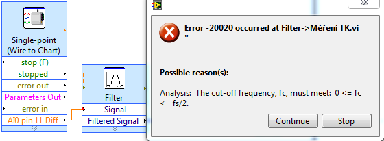
Hello, I'm trying to filter the data of voltage point unique task, but there is an error of frequency... I have set at 120 Hz sampling frequency and I want bandpass filter for example of 30 to 40 Hz...
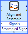
So, where is problem? I tried to use a timed loop or "align and re - sample" sampling frequency, but this filter still does not work...
You know, how to use this filter with single point task? When I do my own filter FIR with the same settings, the results are not same, this is the reason why I want to use this filter.
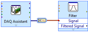
If I use DAQ Assistant, there is no errors, but I can't use for other reasons (1) I can't use single point and all daq assistant, daq assistant 2) can't do pressure)
These images add nothing to the discussion. If you buy a single point at a time, you have NO frequency and cannot use the normal filter function. Do what I said or use multi-sample reading or single reading point and build the table before making a filter. Best is to use the acquisition of data with several samples.
-
Hi all
I have a set of data (table 1 d with a value of 500) and I use the basic filter of the LV (smootihing with average mobile, rectangular, half width = 1) for smoothing noisy data. As you can see in the photo, the curve smoothed red seems to offset 2 pixels with respect to the original blank data. If I take the difference btw the original and the filtered data in the measurement of noise (green curve), then it will be exaggerated due to this change. You can write code to compensate for this, but I wonder if there is a way to correct it in LV also, what are the causes exactly this change?
The second photo shows the sub vi to do filtering, etc.
Thank you!
The moving average of smoothing itself is a low pass filter. Like any digital filter, it has the answer. Don't forget, phase in nature is the delay in time. There are some filters with zero delay/linear delay but apparently the smoothing filter isn't one of them. When you configure the filter, transfer function Select display mode, you can find the answer in the second chart. Notice that it has a non zero delay to phase in most frequencies.
You can also increase the width of the filter and you should be able to watch the delay increases as well. So, not much you can do with it other that realign the signal after filtering if you wish.
-
How can I get good results from the detection of matching/shape of reason for this image?
I need to be able to identify all nine squares in the first image (0000094718...) and others like him. I tried to detect shape, filtering and geometric pattern match. I tried to vary all parameters within these functions. I tried the image preprocessing (and the model, if any: usually created from only one of the boxes) with thresholding and/or a muliplier before using the detection or the corresponding function and I still can not get all nine boxes and only these nine boxes.
Can someone offer some help? Ideally I would be able to use the shape detection, because it returns the coordinates of the corner rectangles and those who are particularly useful to me. What confuses me about this feature, is that after setting the width/height minimum/maximum of rectangles to find, the program seems to ignore these instructions and returns matches outside these limits.
It would be even better to be able to have a script which will identify all nine boxes in two attached images. The boxes in the second image (X820A32) are more square.
Thank you
Holly
Try the attached script. I think that you use only may not be the optimal threshold values. You may find that you want to use a smoothing filter before making the threshold. This should also help with nuisance particles.
Maybe you are looking for
-
The answers that your Web site provided no did me not nothing good. I use a master password to Firefox. Now Firefox don't ask me if I want that it to remember a certain password that I entered for a Web site. In the 'Options' tab, I said Firefox I wo
-
How to increase the memory shared on the Satellite 1800-700
Hello I upgraded the memory on this computer to 512 MB some time ago and I was wondering if there is a way to increase the amount of shared memory that uses 8 MB graphics card? I'm using xubuntu 6.10 and I find it pretty slow. I hope to increase the
-
where can I find firefox.exe directory
How to locate or join the firefox.exe program in Windows 7 Professional? This has happened Each time Firefox opened == I downloaded it
-
Windows installation Tech Preview 10 on 13 of Yoga than double trunk
Hi guys,. I'm new here, but have 13 Yoga for almost 2 years now. But this isn't the case if I have problems to install the Windows Technical Preview 10 on my machine on a new partition. I lowered the storage on my Windows8_OS with about 40 GB drive.
-
error on bluescreen 0x0000008e
When you use the computer, the screen turns blue then says something about memory dump and give full disk analysis code 0x0000008e, tried and it says no errors of ideas why and how to fix it, he also said something regarding the RAM Thank you