Pull-up external USB-6009. digital output (open collector) allows onboard external + 2.5 V output?
Pull-up external USB-6009. digital output (open collector) allows onboard external + 2.5 V output?
Hello
I want to config output digital USB-6009 to + 2.5 V above and 0 V digital output low. I know I can config USB-6009 digital output open collector with resistance to pull-up external, that can be applied with + 2.5 V power source.
My question is: can I use USB-6009 Board + 2.5 V output as the current source of resistance to pull-up? What resistance is a good number for the resistance to pull-up, if I can use this configuration?
Thank you much for the help.
Cathy
Hi Cathy,.
The digital USB 6008 front-end server looks like this:
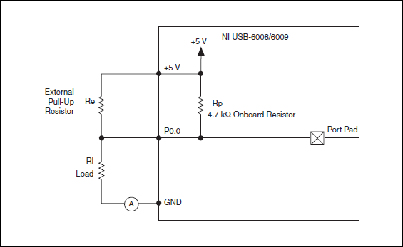
So, there is actually an internal pullup to 5V 4.7 kOhm resistance when the device is configured to open collector.
If you want to display 0 to 2.5 V, I would look in a resistance of polarization of 4.7 kOhm between c and ground (according to the rest of your tour).
Best regards
Tags: NI Hardware
Similar Questions
-
NI USB-6009 digital outputs are active when connected to a PC - I'm not that
I have a small problem:
All outputs digital NI USB-6009 module become active when the module is connected to a PC when no VI is running.
As soon as I start my VI, which controls the module, all the outputs are disabled (now inactive).
How can I achieve this, outputs are inactive if the module is connected to a PC with no program running?
johanneshoer wrote:
I have a small problem:
All outputs digital NI USB-6009 module become active when the module is connected to a PC when no VI is running.
As soon as I start my VI, which controls the module, all the outputs are disabled (now inactive).
How can I achieve this, outputs are inactive if the module is connected to a PC with no program running?
The USB-6008/6009 case has a pull-up internal (4.7 kOhm) resistance. This causes the outputs digital on the device to have a startup logic high State. t is not recommended to use some sort of resistance of menu drop-down. However, what you can do is add octal buffer like the 74HC541 stamp and a digital output to control the sorting of the 74hc541 state mode. Connect the OAS and CEO input signal. A Summit on the pins of the latter will be sorting the output of the buffer State. Therefore, no output signal will be present until you pull the stems of low control. The USB-6008/6009 case have a 5 volt output (200mA max), you can use the buffer.
-
USB-6009 slow output signals using SignalExpress - error 200077
We have a Council of USB-6009 and Signal Express version 3.5.0
We want to generate low-frequency, analog and digital outputs to simulate some slow movement process.
We have created the signals and their generated as output, put when we RUN the project, we get error 200077, which seems to indicate that we must use On Demand distribution of signals.
If we choose On Demand, then the generate DAQmx says we have a missing entry.
So, what method should be used with the slow USB-6009 to generate box (.01Hz and slower) analog and digital outputs?
These are 2 of the projects, we tried - using On Demand, N samples, continuous, internal, and external triggering etc..
Thanks adavance for your help...
Welcome to the forums of Steve,
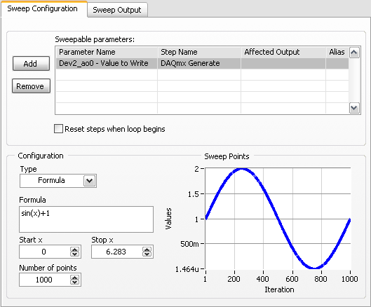
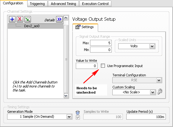
I have good news for you. I played a bit with the sweep and actually got a code facing up to generate a slow signal. I went and tested it with the 6009 and he was able to run without any errors. I joined here, but if you have to open (or anyone else in the future), here are some screenshots of how it works. If this works, feel free to make the forum as resolved while others can locate a solution a little easier in the future.
Scan Configuration:
DAQmx Config:
-
USB 6008 digital output signal
I am VERY new to LabView and have been racking my brain trying to get digital output of my USB-6008. All I want is to be able to get a signal of + 5 V of my digital output when I click on a button. This signal opens a valve on a system I see so when it is pressed, it must stay open until I press the new button. It seems simple enough to me, but I'm not too familiar with LabView. Help, please!
Stripling07
You must first take the LabVIEW tutorials and then look at the links to get started with DAQmx .
The simplest program would be with the DAQ Assistant. Drop it on your schema, and then select digital output > digital line. Select the line when the wizard has completed, click OK. Wire a Boolean value in a table to build and the output of which is connected to the data entry. That's all. You can test the output of MAX (Measurement & Automation Explorer) with the test Panel. Do NOT test with your connected tap. Your valve may require more current that can provide the 6008.

-
NI USB-6501 digital output problem
Hello
I use DASYLab v.11 and I'm working on an interface with the NI USB-6501 where I'm putting a digital high on four ports.
With the module "NOR-DAQmx - digital input", I managed to read the digital inputs of the ' NI USB-6501 ".»
It's only the "NOR-DAQmx - digital output" I can't go to work.
Using 'NI MAX' of NOR I have easily can emmit my four LEDs in the way of my High/Low ports.
But not with DASYLab. When you use DASYLab tension on the ports remains unchanged.
Now, I have a switch module, generating 5/0, directly connected to the digital output module, which is assigned to my four output ports for my task.
I also tried with a module of relay between the two without success. I also tried to use 1.5 above instead of 5 without success.
I use the option 'Bus (0/5 supply) for the module "Digital output".
"NI Max", I configured the ports as "active drive.
Any suggestion of what I might be missing?
Thank you
Martin
Hmm, four ports, or four lines?
A port consists of eight lines. Each line can control an LED (ON / OFF ~ 0/5V).
If you have created a task to dig-out to control a port, 5V to this port sending sets all lines of this port to 'high '.
You need to 255 for each line one too high port (at the bit level: 128 + 64 + 32 + 16 + 8 + 4 + 2 + 1).<- eight="">
Or, you can create a dig out tasks to control four lines of a specific port.
Four lanes of the EEG DAQmx DigOut module.
Each of the channels of the modul will feed a single line of the task/device.
Four switches will then turn the lights, or turn off.
Make sure, that the 'bitposition' is the number of correct line (see picture).
-
USB-6211 - digital output not supported?
Hi all
I can't use the USB6211 device port... I use daqmx with Delphi7 API functions.
First of all, I tried this:
DAQmxCreateTask('', @TaskDO);
DAQmxCreateDOChan (TaskDO, PChar('Dev1/port0'), ", DAQmx_Val_ChanForAllLines);
DAQmxWriteDigitalU8 (TaskDO, 1, 1, 1, DAQmx_Val_GroupByChannel, $FF, @written, nil);I had an error in the DAQmxWriteDigitalU8:-200012 (= digital output not supported). (???)
OK, I tried to disable autostart option based on DAQmxWriteDigitalU8 and insert a 'manual' start in the code:
DAQmxCreateTask('', @TaskDO);
DAQmxCreateDOChan (TaskDO, PChar('Dev1/port0'), ", DAQmx_Val_ChanForAllLines);
DAQmxStartTask (TaskDO);
DAQmxWriteDigitalU8 (TaskDO, 1, 0, 1, DAQmx_Val_GroupByChannel, $FF, @written, nil);
DAQmxStopTask (TaskDO);Now, I got the same error in DAQmxStartTask:-200012 (Digital Output not supported, once again). (?????)
I don't understand.. 'Digital output not supported "? USB-6211 has 4 lines! What is the problem?
I want to just turn on and off the lines from code...
-Cs George-
Well, finally I figured out...

Here is the solution:
DAQmxCreateTask('', @TaskDO);
DAQmxCreateDOChan (TaskDO, PChar('Dev1/port1'), ", DAQmx_Val_ChanForAllLines);
DAQmxWriteDigitalU8 (TaskDO, 1, @dummy, 1, DAQmx_Val_GroupByChannel, @bitmask, @written, nil);Digital output lines are on port1! Corrected parameter.
And the part of the interface of DAQmxWriteDigitalU8 had to be changed (in nidaqmx.pas).
I don't know why, but the AutoStart (dummy) parameter in the DAQmxWriteDigitalU8 function is ignored: function always starts task automatically, regardless of the value of autostart. But this isn't a problem for me.-Cs George-
-
USB-6289 digital output signals setting
I use a USB-6289. I am writing a CVI application that uses this device. I need to put the digital i/o pins as outputs. In the CVI app, I know I can create these tasks with the tools-> create/edit DAQmx tasks. He created this:
Int32 CreateDAQTaskInProject(TaskHandle *taskOut1)
{
Int32 DAQmxError = DAQmxSuccess;
TaskHandle taskOut;DAQmxErrChk (DAQmxCreateTask ("DAQTaskInProject", & taskOut));
DAQmxErrChk (DAQmxCreateDOChan (taskOut, "USB-6289/port0", "))
"DigitalOut", DAQmx_Val_ChanForAllLines));
DAQmxErrChk (DAQmxSetChanAttribute (taskOut, "DigitalOut", DAQmx_DO_InvertLines, 0));* taskOut1 = taskOut;
Error:
Return DAQmxError;
}So this it puts in place but not to write the data. My question is what is the command to write the data?
Also I was wondering if the code source of any example that shows how these commands are made? Is it possible to configure the bits individually? I only need to use 5 of these pins as outputs so t would be coll if I could write that the bits D0 - D4.
Are there documents written on these commands and how they are used?
Thanks in advance
A DAQmxWrite writes the data.
Go to help > examples > material input and output > DAQmx > digital generation.
If you specify the lines instead of a port, you can use as the number of bits you want.
First glance using the ICB.
-
Error writing to usb-6343 digital output
Hello...
I have a trask to produce some digital waves... so I use usb daq-6343. to start, I am writing 1 simple value (i.e., 1) to the first pin of the port. but I get the error here, I enclose error png and part vi of the code... Please help me here...
Thanks & best regards,
-
USB 6008 always low digital output
I have a work 6008 usb with a LabVIEW program compiled running on the time 2014 engine run that I use to toggle the relay via the digital ports (open collector). The circuit is such that logic 1 means power off. The code has been run 24/7 for the weeks withouth a problem and all the lines of logic then low and stiff it. The code continued to run and was going well. If you stop, the exit code and restart it works and has been for days. Running Windows 7. Any ideas?
Thank you. I'll give it a shot.
-
digital output usb6009 does not switch does not correctly
Hello
I have a little problem with my 6009.
Basically, I switch the inputs of a Demux (74HC238D) (3 lines) write an address on it to select rows of data off the Demux.
The signal from the acquisition of data through an FPGA and the signal is displayed on the input pins Demux. That is the problem.
(It is worth noting that the FPGA is well programmed (coz if it was'nt then the signal would not get the demux in the first place.))
When I connect the inputs of the FPGA to 3 digital lines of data acquisition and scroll lines (turning each one WE and OFF), the signal appearing at the Demux pins is not a proper logic level. (the voltage I measured the scope is about. less than 1.1 V). For this reason I choose any line, Demux output will always be on the first channel and will not select the other channel.
I tried the same test 7 connect supply of 5V data acquisition (each line) and after having programmed the FPGA, the correct voltage level is available on the DEMUX pins. The problem occurs when I try to scroll through the entries via the software.
I'm not which is the cause. My belief is the acquisition of data.
What are your suggestions?
Thank you
Labmat
Hi Labmat,
The first thing that jumps out to me is the fact that you use these signals to interface with an FPGA. Outputs digital USB-6009 are 5V or 3.3V TTL and commonly FPGA i/o is 3.3V. Just to double-check, as FPGA did you use?
Q: When I connect the inputs of the FPGA to 3 digital lines of data acquisition and scroll lines (turning each one WE and OFF), the signal appearing at the Demux pins is not a proper logic level. (the voltage I measured the scope is about. less than 1.1 V). I tried the same test 7 connect supply of 5V data acquisition (each line) and after having programmed the FPGA, the correct voltage level is available on the DEMUX pins. The problem occurs when I try to scroll through the entries via the software.
A: This no doubt hits the nail on the head. First of all, I'd be inclined to not use program any software directly and instead use some of the tools for debugging I/O connectivity that come with the Driver NOR-DAQmx. You can get these from the measurement and Automation Explorer (MAX).
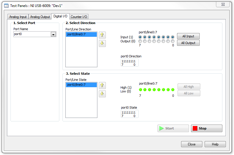
' ' ' ' 'Start-up' all programs ' National Instruments ' measurement and automation.
Expand the tree of devices and Interfaces in the left pane, and then select your USB-6009. Using the Test panels button on the right pane, you can quickly perform digital i/o with the device.
Our best bet is to first take a multimeter and see if we can measure the correct voltage is distributed by the correct pins on the USB-6009 case.
Now, by checking the box USB-6009 Datasheet, we can see that, on Page 17, there are a couple of different ways that we can configure the method by which the output signal is driven out of the unit; We have Drive open and active collector mode. It will assure you that since you are trying to send a signal to the FPGA, the unit must be set to active training mode, in order to generate signals from 0V to 3.3V . Output open collector allows the generation of signals from 0V to 5V . This can be done through property OR DAQmx nodes in LabVIEW.
In terms of current...
The + 5V line that you used for the FPGA Nailer is evaluated to 200 my. General DIO lines on the USB-6009 case can generate a current up to 8.5mA. This limitation fits the specifications of digital input of your FPGA?
-
OR USB-6009 can produce the constant current source/sink?
Hi all
I have a card NI USB DAQ to 6009. I need a battery for constant (charge/discharge current<1mA) and="" simultaneously="" monitor="" its="">
I was wondering if I can use USB-6009 of output constant source/sink of charge/discharge current the battery? I've seen a few threads that says 6009 impossible to output constant son of currents, but other says we can use the digital output to provide the current, but it was not only described how.
Thank you.
All the outputs of the USB-6009 case are sources of tension and all have current limits low. There is no way to generate outputs current controlled directly from this device.
What I would do (and have done) is to build circuits of external current source/sink with an op amp or a transistor and allows you to enable or disable a digital output of the USB-6009. If the current must be adjustable, use an op amp circuit that takes an input of the analog output of the USB-6009 voltage to set the current. Use an analog input channel to monitor the battery voltage.
Lynn
-
Typical values for the external resistance of pull-up on a line of output digital NI USB 6009?
Hi all
I use a digital line on a USB-6009 to control a SSR by the attached diagram (in the manual USB 6009). I don't have access to a variable resistor or box of 10 years, so I'm hoping to get a good approximate estimate for the value of Re. When I connect the CRDD at a 5V supply, it shoots 8.2mADC when closed.
Any suggestions? Is there any other information I can post for help with the guestimations?
Thank you!
I have found an old box of decade Heathkit and understand the degree of correct resistance 100 ohms.
-
Current output digital USB-6009
Hi, I'm trying to increase the voltage output digital device USB-6009. I read a few topics on the use of a relay, but I couldn't get it.
I was thinking of using power 5V on the map because there current 200mA on it, but when I use it with open-collector output, it cannot change the relay. When I measure the current between
5V and ground: 200 ma,
5V output, I read a value around 30-40 my.
Why can I not use this 200mA with output? It is the Relay that I use.
If this is not possible, can I use an external power supply 5V (with more current) and a digital output to pass the baton without damage the 6009?
Outputs digital of the USB-6009 confined to 8.5 my. Your relay coli requires much more than that. Even if the power source can provide enough current for the relay, digital output can not put.
The solution is to use a buffer of extermal. The ULN2003 can switch currents up to 500 my and voltage up to 50 V while being controlled by digital output.
Lynn
-
Configuration of the digital output in the USB-6009
I have a card for the acquisition of data USB 6009. It seems that him when DAQ card is turned on, it is always default to digital output of 'High' or 'floating '. I want to default to 'low '. Is there some setting I want to 'program' the hardware DAQ to have all the outputs low when it is powered on the value? Right now I have manually enter MAX and adjust the level 'low '. Thank you very much for your help.
Sid05,
Yes, it's low of 820 ohms. Unfortunately, the way in which the system is built, it is the only choice you have without having to build external circuits such as SnowMule suggested.
AK2DM,
Thanks for pointing the USB-6000. Finally a real, if limited, the DAQ hardware. Nevermind, he was only 4 DIO lines.
Lynn
-
How to measure the digital output of the linear actuator on USB-6009?
Hello
I am a new user of Labview and need help to measure a digital input signal.
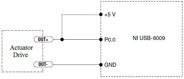
I have an actuator Bimba Original line electric with a motor continuous integrated with encoder, drive and the controller. The drive has a programmable digital output that I put as a tachometer output that emits pulses of square wave 100 per turn of the engine. I put the engine to make a total of 56 rev in 22 dry. I want to measure the speed of motor rotation labview real-time and synchronize it with a few other analog input signals. I wired the actuator for the USB-6009 case as shown below.
I opened the test i/o digital USB-6009 Panel and fix all the lines of port 0 as inputs. However, when I click on start and run the actuator, p0.0 led flashes, as indicated below.
Shouldn't the led blink in response to revolutions of engines?
I want basically to collect the drive pulse signals and convert them in rpm on labview.
ahsan2 wrote:
I have it wired correctly?
It would help if you do not attach the HIGH signal. Remove the + 5V in the circuit.
Maybe you are looking for
-
New BT sim does not activate in iPhone4s
I have an iPhone 4S and have been with 3 using their sim 17 months card contract. To get the best coverage/signal, I decided to change to BT mobile sim. SIM has been ordered and supposed to be activated, but it did not list service. Ironically, my hu
-
Office Jet 6500 - E709c: Scanner does not work, error 4 (3,14,0)
Scanner stopped working after the OS update to Windows 10. Doctor Analyzer could not help. All the drivers are up to date. Any help?
-
HP printer 1600 printing white
my hp 1600 printer printing blank pages continues to spit out blank pages
-
Hi, we live from Netapp for the FIs storage configured as storage fcoe ports, the FIs are FC switch mode. I see the netapp in FIs flogied so the CF part looks good. I was creating a KEEN on the Netapp side and CE marking on these ports connected to t