Pulse or measure of separation of two edge with implicit synchronization in ticks: what about minVal and maxVal?
When I pulse or measure of separation of two edges, using the implicit synchronization, DAQmx chooses (I think) an internal time base appropriate for the measurement. My X series on Board (a 6320) has for example a time base internal 100 MHz. I think I can apply to the use of a base of specific time (using the Set accessor of property DAQmxSetCICtrTimebaseSrc to set the counter to the value '100MHzTimebase' time base). But the docs of the DAQmxCreateCIPulseChanTicks and DAQmxCreateCITwoEdgeSepChan functions (this last one called with the parameter to the DAQmx_Val_Ticks units) make me spend a minVal and maxVal. Apparently, these values are used to determine a time appropriate for the implied timing base (internally). But how to choose the specific digraph/maxVal values? They are obviously dependent on the time base, so it's kind of a situation / the hen's egg. Should I just say '1' or '0.1' or even '0 '? Because I * want * the time of 100 MHz, to use base. Or can I simply call the DAQmxSetCICtrTimebaseSrc after DAQmxCreateCIPulseChanTicks?
1. When you use "Ticks" for units, digraph must be > = 2. DAQmx does not support measures of 0 or 1 "Tick" of a time value.
In general, the parameters that minVal and maxVal are mainly useful for people who are measured in scientific units such as seconds. They allow DAQmx do the dirty work of correlation required range of programming interface with the basics of time available to the Agency and to make a judicious selection automatically. For people like you measure in ticks, DAQmx won't do the thinking for you anyway, so just give them plausible values.
2. Thus, maxVal must simply be a valid 32-bit integer.
3. Yes, you can explicitly configure to use the time base of 100 MHz after the creation of the task, no doubt thanks to the function, you said "DAQmxSetCICtrTimebaseSrc". (I do my programming in LabVIEW and don't know the syntax of the api code text driver.)
I believe that if you do not explicitly choose a time base for a task using ticks as units, the Council will use its default time base. I know there is an api function in LabVIEW to interrogate the database after creating a task, perhaps you have an available too?
-Kevin P
Tags: NI Hardware
Similar Questions
-
I can't open a pdf from last week. I have a Samsung s6 edge with t-mobile. I spent an hour and a half with t-mobile tech support and they told me to email you because they don't know what else to do.
Hi Edwin,.
May I know what is happening when you try to open a PDF file with Adobe Acrobat app on your device Galaxy.
Try this:
Go to settings > Applications > Adobe Acrobat
Under the terms of the App Info, click on clear Cache
Then try to open a PDF file
Still, if this does not work
Uninstall the application
Then download and install directly from APK files.
Adobe - Adobe Acrobat Reader DC Distribution
I would like to know if it works for you.
Thank you
Abhishek
-
Can I stop a separation of two edges with infinite time-out?
Hello!
I use the example VI: "soul two Edge Separation.vi ' (see the Archives of this message) with a USB-6251and NI a timeout that is infinite because I Don t know when I need start a new measurement. With the features I need to stop the DAQmx VI "DAQmx Read.vi" If this VI Don t stop in a PRE-DETERMINED time (10 seconds), but I do not know how I should do.
I can´t use a guard dog, because the NI USB-6251 haven´t housing a guard dog. I try to reset the daq with "DAQmx Reset Device.vi", but when I do, the daq break. I also try to use 'DAQmx control Task.vi', "DAQmx's task made" and "DAQmx Trigger.vi" with reference - no, but this screw never run until the end of the "DAQmx Read.vi.
Thank you.
Try the joint. It is registered as 8.0 because I do not know what version of LabVIEW you use.
The card I have in my machine cannot perform the task you want, so I don't have a chance to test it.
-
Pay your bills online. I suddenly can't pay them through Mozilla, even if I can pay through Explorer. Why has this happened? The two companies say it's my browser.
Hello, please try to reset firefox and see if that can solve the problem...
-
How to determine when my separation of the two edge counter starts counting
I looked through a ton of Daqmx properties, the web and the forum OR to find answers to the question "How do I determine when my meter of separation of two shows actually starts to count.
So I've set up my meter of separation of two edge on two channels known PFI two trigger when they detect a positive benefit. Now, because I use an accelerometer to my first impulse, my concern is that it could possibly be triggered until the test is run. So I would like to have labview (if possible) be able to question whether or not the first trigger was triggered and the meter started to count. If this information is not known, I could run my sample and get a value that is incorrect. Knowing whether or not the meter started cash before running the test, prevents the operator running a test, effectively consuming a test item.
Thanks for any information.
-John
I would like to poll the CI. Count property.
Once the first edge is saw that the count will begin incrementing.
Best regards
-
separation of two edges using a digital output
I am using a DAQ, PXI-6229 map and programming in c# .net.
I'm claiming a falling edge on PFI12 used as a digital output, and I need to measure the time between this edge and a second front on PFI8 used as a digital input. I have implemented the code using some examples I found. I don't know when to to argue the signal on PFI12 in order to be read at the right time. Playback must be put in place before the signal is asserted, but I do not know how to set it up it up properly.
Here is the code I have so far:
Public Sub MeasureAcquisitionTime()
{
DigitalSingleInputTask = new Task();
CIChannel counterSetup;
firstEdge = CITwoEdgeSeparationFirstEdge.Falling;
secondEdge = CITwoEdgeSeparationSecondEdge.Rising;
Double minTime = 10-3;
Double maxTime = 60F-3;
String auxCounterInput = "/" + CardName + ' / PFI12 ';
String gateCounterInput = "/" + CardName + ' / PFI8 ';
counterSetup = DigitalSingleInputTask.CIChannels.CreateTwoEdgeSeparationChannel)
CardName + ' / ctr1 ', 'counter',
minTime,
maxTime,
firstEdge, secondEdge, CITwoEdgeSeparationUnits.Seconds);
counterSetup.TwoEdgeSeparationFirstTerminal = auxCounterInput;
counterSetup.TwoEdgeSeparationSecondTerminal = gateCounterInput;
DigitalSingleInputTask.Control (TaskAction.Verify);
runningDigitalTask = DigitalSingleInputTask;
counterInReader = new CounterReader (DigitalSingleInputTask.Stream);
Double data = counterInReader.ReadSingleSampleDouble ();
}I'm glad to hear it.
paofthree wrote:
Is there a way to make a measure of separation of two edges on the analog inputs of the PXI-6229?
The only way would be to constantly acquire the analog input voltage and calculate the separation of the two edges in the software.
Best regards
-
can anyone tell how to compare two documents with two controlled with the same mouse pointers
can anyone tell how to compare two documents with two controlled with the same mouse pointers?
Windows and OS X can only display a mouse pointer - it is created by the operating system, not the application.
-
Separation of the two edge triggered measurement
I try to use a USB-6259 device to measure the time of separation between two signals. I need to measure the time only after another trigger signal was raised. I tried to configure the task of separation of measurement with a trigger to start on a rising and also with a break so that the task will stop if the trigger signal is low. However, I get errors that it is not supported. Is there anyway to trigger this type of measure?
I thought about it - beginning of arm relaxation.
-
How can I use two counters simultaneously to pulse width measurment
Hello, everyone!
I'm new to Labview. I currently have some cDAQ9171 and width measurment with 9401 impulses. My understanding is that the 9401 was 4 meters, which means that I can use these meter separately. However I have the following problem.
1. I use ctr 0 and ctr 1 (PFI 1 and PFI5) to measure two different impulses. However, it seems that there is an interference between two counters. How can I make two counters working simultaneously and separately?
2. I first try a pulse width measurment counter in Labview signalExpress. My pulse width is about 0.4ms. However, I can't get the right result, if I choose the starting edge is on the rise (the results always around 20ns. Only if I revise my pulse and pick the starting edge is down, I can get reliable results.
I'm confused about these issues for about 3 weeks... Is there someone can help what can I do with that?
I have attached a simple vi...
Thank you very much!
-
Hi all
Maybe a newbie question, but I haven't found an exact answer so far.
I have two signals.
A slow which I want to use as a trigger of power and a quick where I want to count the edges.
I want to measure the number of edges of the fast signal occurring between two rising edges of the slow trigger signal.
I read the help of separation of two edges and examples and always found three signals.
So my question.
Is it possibel to use two separation of edge with only two signals and connect the a slow (trigger)
both DOOR and to THE?
Or maybe someone can tell me how do to best accomplish this measuring task.
Many thanks for any help,
Ralf
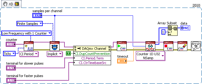
Since a picture is worth thousand words, here, try something like this:
Here's the idea:
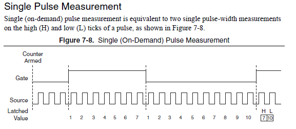
1 counter is set up for the period measurement with units on the ticks. Normally this would record the number of edges of a base clock of internal time between consecutive edges of the pulse train whose period is measured. Here we are substituting the normal behavior a little bit.
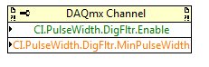
2. Notes the DAQmx Channel property node. Let's say the task of counting your pulse train faster * rather * count of a database internal time clock.
3. in the time mode, the counter will be reset to 0 in each cycle of the signal period. So you will get a buffer zone to tell you how many more fast pulse occurred between the values * each * consecutive pair of slower pulse.
4. we will ignore element 0 of the array because its value will be quite random, representing the start time of the task until the edge 1st period. It is very often not explicit.
-Kevin P
-
I use a timer/counter with DAQmx 6602. I use the separation of two - available via DAQmx cash edge. Count between the two edges works properly, however I do not know how to read the value of the counter during the counting operation (i.e. after the first edge triggered the beginning of the count, but before the second edge triggered the end of the counting). I'll have to wait for the second goes off the edge of the end of the countdown until I can get a counter value. I need to be able to access the current value of the County during the count operation. This was possible in traditional DAQ. How can it be accomplished using DAQmx?
Ah shoot - I was afraid that this might be the case (for what it's worth, my series of X returned intermediate values, but the material and the underlying driver are quite different)...
You just need to take one measure at a time or you are buffer several measures of separation of the two edges at the same time? So just to take one measure at a time, you can set a task of edges of count using the database internal time as the source using an arm start trigger (first edge) and a sample of clock (second Board) to work around the problem.
Best regards
-
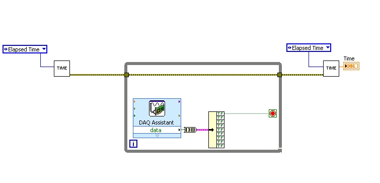
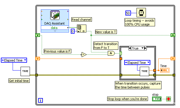
Measure the time between two digital pulse
Hello
For a non-critical calendar application, I need to measure the time interval between consecutive TTL pulses, ranging from the order of 0.5 s for a few seconds, with a low accuracy of +/-10-50ms. The interval being measured varies between the rising edge of the first pulse and the front of the next and so on.
I have several input lines I need to deal with. Because it's a critical machination low cost, I don't want to use digital counters for each line, so I work with an acquisition of data USB6008 and have connected the input rows TTL on the digital inputs of the device. Avoiding will be sufficient.
I found a good example of VI on discussion forums that does almost the same thing, only it uses instead of the DAQ Assistant user input. The VI works including the time the program going on in a while loop. I replaced with the DAQ Assistant output (a channel) user input in the hope that it is still work.
When I run the program in "run once" mode, it seems to work perfectly. However, in "continuous run" it measures only a very small interval, probably just the time between two samples. I think it has something to do with the help of a while loop in combination with the DAQ Assistant. Anyone who has any suggestions how to solve this problem?
Thank you!
OK... first of all, you should never use the button "run continuously. I wish that NEITHER would be to eliminate it, but told me that it is sometimes useful for debugging. If you want your program to run over and over again, use a while loop with a stop"" button.
If I'm reading your code correctly, you make your initial moment, and then collect data from data acquisition. When one of the channels is "T", you stop your loop and the end time of capture. (By the way, why you convert your table to a cluster? Why not just index the appropriate channel in the table directly?)
Since you want to capture the time between two consecutive pulses, you need to know when a transition has occurred... i. e when your digital line went from F (no pulse) to T (pulse start). This will give you your forehead. Right now, all you're doing is looking for a value T - so you have no way of knowing if you are looking for to the previous impulse again, or a new impetus. You also burn 100% of your processor with the way you have your programme in place.
You need a small loop delay so that your VI is not 100% of your hogs CPU time. Given that you can live with an accuracy of 50msec, what I suggest that you use.
See attached picture for you give an idea of how to implement. He will probably need some refining operations, but it should point you in the right direction.
I hope this helps.
-
Full range of pulse width measurement
Hello
I'm having a problem with the measurement of PW, I need to read an operating cycle within a range of 0% to 100%. The problem I have is the signal does not cross the Middle time enough baseline to measure or the histogram cannot be used because the amplitude is zero. Yes, this is obvious, because there is no pulse, that's basically all true or all false these two extremes, but the pulse measurement vi cannot handle this. Is there another way, I could measure the market factor, so that I can see if there is a hollow (0%) or high (100%) and everything in-between without errors? Even when I measure the PulseWidth in the method of the Ridge, rather than the histogram method, which gives me more time to remain at 0 or 100% before it gives an error, the measure see the signal as duty cycle 50% (still a times obvious because it is neither salvation nor low for any length). So if I could still read 0% or 100% error free, how would I be able to block the two extremes of the never read? My entry is the acquisition of data, so I can't just 'limit' my input to the source signal...
Any suggestions?
Thank you
-Corbin
Hey, Henrik, thanks for the reply,
I didn't really know how to integrage over a period of time in LabView, and I read a wave of digital squares (duty cycle). I found that I needed to omit extreme values such as 0% and 100%, so I couldn't find a way to do this with one under VI. What I found is my solution: I knew that + 12V has to be 100%, and 0 v is expected to be low, so I just used 'Amplitude and level measurements' sub VI read the RMS value, used a table that I recorded correspondence (via MatLab help), and I have more problems with errors due to levels of reference of histogram (do not use histogram now...). My application can read everything from 0% to 100% and he returned my correct data after handling. Success!
He could go about resolving the issue differently, but it works.
-Corbin
-
single pulse width measurement
Hello
I'm trying to measure the duration of a single pulse using ctr0 on an SMU-6361.
The signal in the attachment Capture7.jpg, goes PFI 9, ctr0 door.
The problem is that the counter see ' s the front up and stops. The pulse width is not given as can be seen in the output (Capture8.jpg).
I get the same results by using Meas_Pulse_Width.vi example.
Is something wrong with my SMU-6361?
Oh, I think I know what it is.
Change the task "pulse width" (a single pulse of height) instead of "Pulse" (the high and low time of a pulse repetition measures). Change the DAQmx Read to use Ctr > single sample > DBL (instead of pulse). Change the property filter node digital to use the corresponding properties of the "pulse width" (the filter is still necessary):
The task of the pulse was not period initially because you receive a series of noise pulse repetition (and so it was a very low period). With the filter, this time since the noise disappears now and the single pulse did not finish measuring the pulse (which requires a high and some time):
For the record, I agree that it is confusing that there is the "pulse" and "Pulse" measure and they do different things.
Best regards
-
with pulse width measurement external sample clock
Hi all
I use a NI 6220 (programming with ANSI C) Board and I would like to make a "unique pulse width measurement' by using a signal from the outer door and an external signal source.
The program and the card with the help of the "DAQmxCreateCIPulseWidthChan" command works only partially as expected. Namely, the outer door has worked, but the map uses the internal time of 80 MHz base signal instead of the external source connected to the source by default PIN (PFI, 8).
I tried send an another PIN PFI on the default source pin using the command 'DAQmxConnectTerms', but this did not help either.
Obviously, I'm missing something...
Best, Uli
Hi Uli,
I posted in your thread here.
Best regards
Maybe you are looking for
-
Product name: Pavilion dm1-4000au Product number: QG411PA
-
AMD Radeon HD 6990 compatible with HP p7-1245 diamond? AMD Radeon HD 7450 Crossfire is the best?
I play SWTOR with 25 mb internet and can't play on the spot. Just try to solve the problem of graphics agitated with the AMD Radeon HD 7450 card provided with the desktop HP p7 1245. Wouldn't be better to go with a configuration Crossfire or more pow
-
Hello I have e hp h8-1309eb want to put too much new grapp.msi gtx 970 games 4 g change the power supply or not? change the other things? Sorry for the bad English...
-
Am I allowed to sell sample promotional/not for resale of Microsoft Flight Simulator program?
I have acquired to a program of Microsoft Flight Simulator that is still sealed thrift store. I thought that maybe I could sell it online, but I didn't get in trouble with Microsoft. It has stickers that says 'SAMPLE NO PROMOTION for RESALE' "FOR EMP
-
Wireless network adapter not working not not for HP Pavilion dv4 - 2020ca
Hello My wireless network adapter does not work after my computer crashed. Here are the details: The product name and number: HP Pavilion dv4 - 2020ca Notebook PC Operating system installed: Windows 7 64 bit Error message: After the accident, there i