pulse wave simulated
Hello
I try to count the edges of the wave, or simply if a square wave goes from 0 to 1. However, I don't want to use the built-in meter to data acquisition. I want this to be purely software metering without using data acquisition. When I try to detect the edges with a Subvi I use, it will work until the frequency is high enough and it will not detect the edges. I'm not sure how to count the edges from there. I tried to use a function box and saw the increase in the real part when he was 1, however it would be permanently as long as the signal was high.
Thank you
I thought about it without your help. Thanks for nothing!
Have a great day!
Tags: NI Software
Similar Questions
-
external clock or wave pulse or sinusodial?
Hello
I'll plug an external clock to 6711 map source. But I wonder if the source should be trains of pulses (wave squre) or it might be vague sinusodial. When we say the frequency of the clock, it means the occurrence of the rising or falling on board but not the pulse, right? And what is the range of voltage for the clock signal?
Hi dragondriver
The external clock should be a pulse train, not a sine wave.
When we talk about frequency, as you said that it: the appearance of rising or falling edges within a period determined.
Voltage range must be from 0 to 5V.
Concerning
-
Hard, I try to find a solution how to use external ABZ, quadrature encoder pulse to retrigger and clock repeatedly the same AO signals (and). A and B legumes should clock AO and Z-pulse wave should restart the wave early. Is this possible with card 6221? Can provide you the code example?
I use LV8.0
Thank you
Kevin,
Thank you for picking up the thread.
I understand your example and I already had working direct synchronization of the AO and MAKE the waveforms using external impulses. The problem is that my application cannot invoke the correct number of A pulse will run same waveform for months. I have to use Z-pulse to maintain synchronization in the long term. That's why the task should be redeclenchables.
I have made some progress since yesterday on the use of the example attached 'retriggerable_ao - NOR .vi' and the decoder external t.i. IC, which has transformed two 1024 A, B encoder in dish 4096 pulses/turn. My CO task then divides this frequency to 1024 (4 points per period). This regime of AO - redeclenchables DO so usually seems to work.
The problem now is that this chip must have a clock (~ 100 kHz or more) to work, and I don't want to build generator external too.
Y at - there no way to get all the signals of high frequency signals (100 kHz, 20 MHz or 20 MHz base time) USB-6221 Board any PFI available pine asuming that all of my commitments in Task-resource in this example are needed?
I tried a lot of things yesterday, but all the clock signals are either committed or roads are anavailable. I don't understand why I can't tap into it?
Any thoughts?
Mikhail
-
How to generate a pulse with the signal generator?
Hello
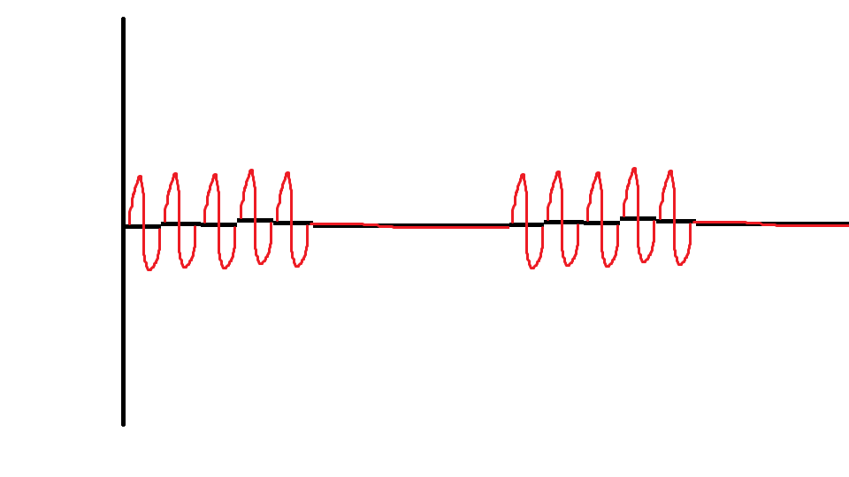
I would like to ask if anyone knows how to use the Elvis platform to generate a regulated pulse wave?
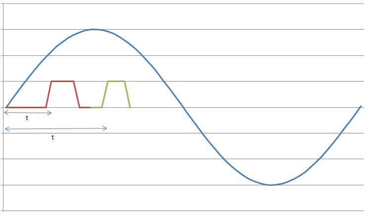
It should look roughly like the picture above. A sine wave with the regulation.
Anyone who can answer my question please respond to my post.
Thank you.
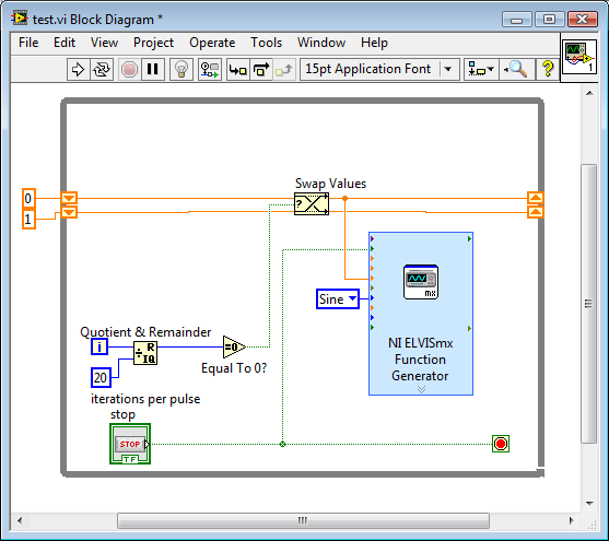
You are using LabVIEW to generate the waveform or using the Soft front panels? In LabVIEW, you can use the express VI generator function and specify the Type as "Sine". Then, simply change the amplitude of the sine wave. During the actual pulse, the amplitude would be what you want (i.e. 1 V) and while the pulse is idle, set the amplitude to 0.
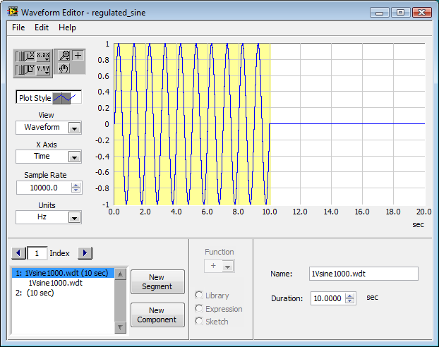
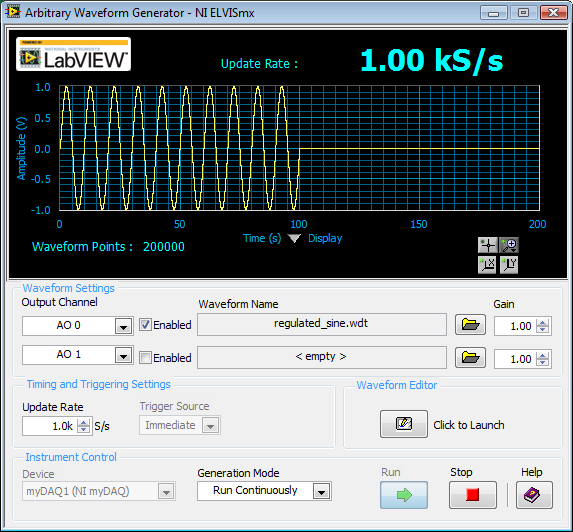
If you use the soft front panels, you can use the Waveform Editor to create a waveform that includes a sine wave for the length of your pulse and then the values of '0' for the rest of the time. Then use this waveform in the flexible front of the arbitrary signal generator. Simply create a component of sine as the first part of the wave and then add another element to a level DC '0' for the rest.
-
Measure the time between the ridges of the periodic input signal
We have built a circuit which is supposed to mimic an Exercycle. We have an IR switch and a spinning wheel, the rccb meets a comparator circuit and the output of the element of comparison, we have running in LabView. We successfully were able to measure the number of rotations of the wheel and the total distance travelled by the wheel, but are struggling to measure speed. We cannot find a way to measure the time between picks in real time, which we could then divide the wheel circumference and calculate the speed in real time. The VI I posted has a square wave simulated rather than the signal we receive on our circuit. Thanks in advance for the help.
Jon and David
I think you're overloading the things trying to get the time between two pulses. Instead, you can use the VI Express your measures and select frequency for her custom. Then, you can multiply the circumference of the wheel of the frequency to get the speed.
I hope this helps.
-Christina
-
Is it possible to change the sine wave 'exit' a simulation device?
I work on a LV collection and analysis VI in LabView that interfaces with a CDAQ-9178 loaded with 9215 modules/a. chassis. In the Measurement & Automation Explorer, I was able to set up simulated devices that work with my code and I get the sinewave / 5 (?) standard signal noise %.
However, to really test my application, I need a slightly different sine wave with high frequency (1-10 Hz vs the)<1hz sent="" by="" the="" simulated="" device). ="" is="" there="" anyway="" to="" modify="" or="" get="" the="" simulated="" device="" to="" output="" a="" different="" wave? ="" if="" not, ="" are="" there="" any="" other="" simple="" ways="" to="" simulate="" the="" device? ="" i="" could="" write="" another="" vi="" to="" send="" out="" a="" sinewave="" but="" was="" looking="" for="" a="" more="" obvious="" or="" simpler="" solution="">
Thank you
# You need to do is call an of the generating functions of waveform instead of the DAQmx Read. Place inside a case, the declaration or the conditional structure disable is fairly simple.
-
Hi, I'm having a little trouble with this VI that I'm working on and I hope that someone could help me. What I'm trying to do is to detect the two peaks of a wave pulse measurement file. Each pulse cycle has two summits, and I want to get the times of the peaks. I can get the first highest peak, but I can't seem to get the time for the second pic, you can see in table 2 waveform. It's the only thing that I get and I appreciate who can help me. Thank you.
-
With the help of modulated signal pulse width (square wave) to control when a signal is enabled or disable
Hello all
I am using a modulated signal to labview created pulse width (square wave) to control when a signal is activated or not.
Here is my logic and a concrete example:
(1) the wave source signal is continuous
(2) use a PWM (square wave) created in labview to control when the signal is enabled or disabled
(3) if the PWM (amplitude) signal is superior to 0 play signal PWM is not greater than 0 do not play signal.I use actually this to the sequence step / pulse several distinct magnetic coils using my audio card (which has several channels of audio output), I have a signal in labview played constantly. As to compare it to the PWM (square wave) which controls whether or not the signal is played on each separate channel. That way I can control which coil is on and offshore and in what order they are activated.
I couldn't find an edge detection for a square wave created in labview, so I tried the limits, but it doesn't seem to work unless I change the phase manually and it only goes 1-1. I'm just trying to compare the PWM (edges of the square wave) already created by labview / play a signal if the pulse is greater than 0 and it shuts off the signal, if she is less than 0.
Should I do this another way
TIA
A waveform contains an array of values. You must check every value and respond accordingly:
-
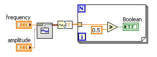
I have a sine wave of 50 Hz and a pulse of the signal on the same chart. The difference in phase between the two is between 0-90 degrees.
Now I need to calculate the time difference between (when the sinusoidal wave passes through zero volts) and (when the pulse increases). The frequency will remain about even for the two signals.
The request is for a three-phase generator. In simple terms, when the difference in time between the passage to zero of the sine wave and pulse increases increases, it means that the load on the generator has increased.
I am a novice user of LabView (version 9, 2009), maybe it's a very simple problem but I was pulling on my hair for the past few days and couldn't understand anything. Any help would be greatly appreciated. I use DAQ USB-6008 to measure these tensions and the impulse of the generator and a sensor
I have attached a jpg file (a graphic that I just did with excel to explain). The time 't' is what I'm trying to measure
See you soon
Zdzislaw
Awais.h,
For problems of this kind I recommend start writing the granular steps you would take to manually fix this problem. You can't say LabVIEW (or any programming language) If you can't succinctly describe the solution to your problem.
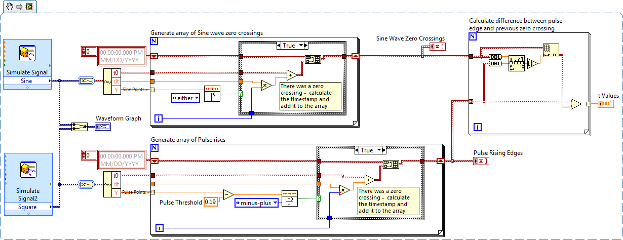
The I want to address this problem is to:
- find all the zero crossing points and edges on the rise
- for every rising edge find the difference between the timestamp and previous passage by zero
Here is an implementation of this algorithm LabVIEW:
-
HOW TO MEASURE THE WIDTH/TIME GAP PULSE ANALOG OF A WAVE
HELLO EVERYONE, IM NEW TO LABVIEW. IM USING NOR USB-6008 ACCESS "ACCELEROMETER READINGS TAP" BUT I NEED TO KNOW THE AMOUNT OF TIME BETWEEN EACH PULSE OR WAVE. IM ATTACHING THE SCREENSHOT OF THIS WAVE. PLS ME GUIDE FOR MAKING of this PROGRAM, I NEED TO KNOW the TIME DIFFERENCE "Dt"...
Thanks for your reply Sir
 , I can get the table of amplitude... but I can't get the time table... could you help me please
 -
Get a UPS for a 51 x: Pure or simulated sine wave?
Long story short, the x 51 is my first office. I got in early 2013 (probably R1?) and have been very happy with it. A few months ago a power failure has occurred, and after that (and despite a surge protector) it became obvious that my graphics card was damaged and had to be replaced. A week ago I went to a friend and she had a UPS for his computer. I had not experienced anything as it existed and I'd like to get one since the power here is not reliable in the past months.
I've done the research, but my big question is: do x 51 computers require pure sine wave or would be mine to agree with simulated type? I continue to see Active PFC mentioned in critical UPS but I don't know if it's important or not for my machine. Someone said that the technology after that 2007 has and requires a pure sinusoid to work properly, that is why I fear that my computer needs it. I'm already trying to keep UPS devices which are more than 400 Watts, according to the recommendations I've seen on this site.
Any help would be great. Thank you!
I used a simulated sine wave (gradin sinewave) on my X 51 for years now (RS600 APC) - it works perfectly well despite numerous power cuts we have here (im in India). I'm using only a pure sine wave inverter (APC SmarUps 750) for my Entertainment Center (TV lcd, audio/video receiver, bluray, etc.).
Power supply for PC/Ada can handle simulated sinewave of sources very well. It is only the components of analog high-fidelity that actually benefit from a sinewave pure Ups imoh.
-
Generate sine wave with noise when simulating Compact Rio on computer test Dev
How can I create a simulated IO vi. I tried to follow the tutorial, but it did not work. Do I need an array of pre filled with data for the business running or I can generate with one express vi? My IO vi does not seem to enter the case of race ever. What is the process of running this VI? He is running once or whenever the main vi trying some samples?
Hi Bartekluk
What tutorial did you follow? Please post the link and I'll take a look.
Kind regards
-
How to read the digital square wave pulses
Hello
I recently bought a blue-white meter. I have successfully read the digital square wave from the sensor. However, I face a problem to calculate the flow rate and the total volume of liquid. Can someone help me with this?
Technical data of the flowmeter can be access to the http://www.blue-white.com/Products/ElectronicFlow/MicroFlo/80000-406_microflo.pdf. And the calculation can be found on page 9. I use NI9401.
Thank you
-
How can you measure a wave of the ECG Simulator using a 6036e?
I have an ECG Simulator I'd like to test. How I would setup a dac 6036E, scb - 68 card to test waveforms? Is there a screw that could help with this problem. Thank you.
You're in luck. NOR has a free biomedical Toolbox that should take you far: http://zone.ni.com/devzone/cda/tut/p/id/9037
There is also a biomedical forum: http://decibel.ni.com/content/groups/biomedical-user-group
-
Cannot install combat flight simulator 3 /disk wander/bf109g_6/sound/bf109_rpm2 wav stop my install
during the installation of air combat Simulator 3 than missg wander rises and stop making everything and uninstall and restarts my pc
Hi Tinkerreyes,
· What is the exact error message?
· Did you do changes on the computer before the show?
You can check if you can access the CD/DVD on another computer. Also check if you can directly open the computer's drive and run the Setup after you copy it to the computer file.
You can also check the underside of the items for more information about Microsoft Combat Flight Simulator known issues:
Combat Flight Simulator 3: known Gameplay issues
http://support.Microsoft.com/kb/331558/en-us
Combat Flight Simulator 3: known sound issues
http://support.Microsoft.com/kb/331574/en-us
Let us know more information about the issue so that we can help you in a better way.
Maybe you are looking for
-
Drivers of network/controller for Satellite C660 Ethernet controller
Hello Yesterday I installed Win7 64 bit in my Toshiba Satellite C660-26Z and ethernet controller network controller and pilot controller PCI simple communications are missing. I have no recovery disk So if someone knows where to find and how to insta
-
computer said lost signal and stops.
our computer stops, said loss of signal. No matter if you are on the internet or simply by using the computer. then it restarts immediately. just as you were stabilized turn it on. All started a month ago. Maybe it's older version of the yahoo toolba
-
How to access the files or records of the administrator
Hello My Toshiba Satellite A-105 recently crashed and I need to reformat the drive, but first I wanted to backup my files from the hard drive. I bought an external hard drive enclosure, set up and plugged in my other computer (healthy). It worked fin
-
Transfer files and settings from PC to win8.1 PC win7
My win7 PC play, so I'm looking to buy a new one. Unfortunately they all win8.1. There are many threads and messages on the complicated transfer data became, but they are confused and with the help of MS sites do not seem to cover this. Essentially,
-
Photo Viewer Windows 7 has changed?
Hello. I use Windows 7 and noticed yesterday that when I open a picture by double clicking on it in a folder, it opens now differently from two days ago. The difference is that the slideshow button which was located at the bottom of the screen in t