PUT ON DIGITAL OUT
I just want the heating turns on if the temperature is less than 0.
Just a part of the major programme is attached. In this case that the radiator is just he Thereare while and the Tower even out the temperature is lower than 0 C. How can I keep it, while waiting on this business for 4 hours.
Without waiting period only works very well.
Please let me know you gus need more information.
I'm using labview 8.2
Thanks for your time
The loop will run every 100 milliseconds. When the elapsed time is 4 hours, the loop stops. But during the race, run the Subvi to measure the temperature. If the temperature drops below 0, the DAQ vi will run, causing your outlets digital market. Is that what you wanted? This vi will run for 4 hours then stop. What happens if the temperature drops below 0 in two hours? Do you want your continuous vi to run for another 2 hours? Please give more details on what you want to do. If it suits your purpose, then the vi is fine as if it were. Only a suggestion. If the reading of temperature Subvi gives an error, you can stop your loop. Use unbundle function to get the status of the error. Son of the State in another function or and combine it with the others or to stop the loop.
Tags: NI Software
Similar Questions
-
Hello
I was intending on using the UMI-7772 to provide control for pneumatic valves signals and also control some return values. There are 16 digital i/o lines available on the UMI-7772. The manual States the 3-27:
«These signals is configurable as inputs or outputs on the movement National Instrument controller.»
I want to configure the UMI while I 10 digital signage and 6 in digital signals. However, no matter what I do, it seems as if the material to the UMI only to entries on port 1 and outputs on port 2.
Can anyone confirm if or not it would be possible to set the UMI with 10 Digital Out and digital elements 6?
Thank you
Sean
Why not read a bit further?
The part of the sentence following the one that you cited States:
"Use the MAX or NOR-Motion software to configure the bit on port 1, as inputs and as outings on port 2-."
In addition, in general, it is not possible (or very difficult) to build a circuit for inputs/outputs configurable lines with opto-isolation in either sense.
-
Can't U330 digital out via the headphone jack S/PDIF
I think the S/PDIF and headset share the same taken green headphones 3.5 mm, right?
I use Onkyo HT-S3100 Home Theater.
http://www.Intl.Onkyo.com/products/system_components/home_theater/HT-S3100/index.html
It works very well with onboard SoundMAX HD v5.10.1.6310 10/09/2007 on XP Pro SP3 32-bit.
Connected through the RCA coaxial port.On my U330 Laptop speakers built-in and headphones work fine.
It's Realtek ALC269 v2.32 6.0.1.5928 on Win7 (7600) Pro 32-bit.I plugged in the cable, open Realtek HD Audio Manager, 3.5 mm tab / RCA (AV) digital output, click on set the default device.
Then I started to play in Winamp, no noise (and no noise) fate of built-in computer speakers and my Home Theater.
The bar green indicators have been posted to the Volume Meter - Realtek Digital Output and also in playback devices (Realtek Digital Output) too.I have also tried using S/PDIF on XP Pro SP3 32-bit (driver of the Lenovo Web site), but still have no sound from U330.
Does anyone have a solution? I bought U330 because she has out digital S/PDIF.
Thank you very much and sorry for my English.
I think it's optical S/PDIF when you put a 3.5 mm plug to halfway in you see a red light? At least, I think that its approach, I took a gamble and just ordered this:
http://www.Amazon.com/Toslink-to-optical-mini-adapter/DP/B0002MQGRM/ref=pd_rhf_p_t_1
Once I get it I'll use it to connect to my Onkyo TX-SR506 via Toslink and post to tell you if it worked or not.
-
Ive got an acquisition of data USB-6211 (and LabView 2009) and Im trying to get the output (5v) device to run a relay on and outside. IM using a tutorial I found on Internet to make the diagram Labview (http://www.pages.drexel.edu/~pyo22/mem639/lab-usb6211DigitalInputOutput/lab-usbDigitalInputOutput082...) and the circuit is simple. I tried to run the DAQ Assistant to test if my output was working, and it is not. I'm not sure if my connections for data acquisition are correct or not. Any help would be useful.
Thank you.
Hello NT_Mech,
Indeed, it is possible that you do not drive enough current for the relay. You can check the specifications of your USB-6211 and see that the digital line will result in a maximum of 16mA. That being said, your relay control current that is needed, you may need to run the two outputs in parallel to offer twice more common provided. Recently, I drove a Soviet Socialist Republic of a Luminary Micro Prototype Board that did not provide enough current as well. In the case of the tat, I was driving the relay by running two lines in parallel.
You can always simplify the software side of things by opening the measurement and Automation Explorer (MAX) and right click on your device and select test panels. "" ' Start ' programs ' National Instruments ' Measurement & Automation then expand devices and Interfaces. Right-click and select Test panels. You can then configure a digital output for your USB-6211 and toggle On / Off and check out.
Best,
-
Audio stuck on Digital Out when Windows starts
I just finished to install 10 Windows on my Macbook Pro retina mid-2015, and whenever I start Windows, audio is stuck on the digital output. I tried to remove Realtek and reinstall it, but no go.
You can perform the following two procedures
Reset the management system (SCM) controller on your Mac - Apple Support
How to reset the NVRAM on your Mac - Apple Support
and test?
-
How to set the clock as a Digital Out Signal in the C API?
My problem is simple, I'm looking for a way get the my device of the series E clock signal (6254) to a digital camera offline. Is it possible to do in the C API? If yes are there docs everywhere where show me how do?
Hi neurostu,
Yes, there is a way. The function is called DAQmxConnectTerms. "" "" "You can find the definition of the function in Start ' programs ' National Instruments ' NOR-DAQ' text Code support" using NOR-DAQmx C reference. "" "On the left, select OR DAQmx C functions" advanced"routing of the Signal'. DAQmxConnectTerms
-
Voltage level of setting Digital Out in NI 6221
Hi all
I work with a NI-6221. I wonder if it is possible to change the voltage level of the digital channels? CurrentY I use "Digital Bool 1line 1 point" as my writing DAQmx.
Thank you
Saridar
No, the outputs are only ttl levels.
-
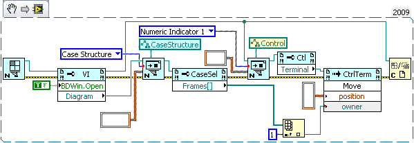
How can I put a digital indicator in a box structure using VI scripts
I am using VI scripts and I try to add a digital indicator within a box structure. I'm able to add the structure of the case and the digital display fine, but as soon as I determine the structure of the case as the 'owner' of the digital (rather than the pattern-block being owner) I get error 1060. Is there a way to get around this?
Note: I am doing this is because this particular (indicator in a case structure) provision will prevent a VI to be inline when it is built. This model will provide no functionality itself, it prevents only inlining. It is added to a larger VI which is used to initialize objects in a simulation, and there are many of them in the total simulation. If they are inlined, it takes a long time to generate the C code and a performance on this VI is not a problem because it is run only once at the beginning of the simulation. The rest of the screw must be inline for performance reasons. Therefore, I am open to other options to avoid a screw of Inline if 'the indicator in a structure of the case' can be done via the script.
If this is not clear, please let me know and I can clarify. Thank you.
Sorry for the mess, it works for me.
Don't mind the empty cluster constants.
-
Use the angular position of the encoder to trigger Digital out
Hello
I am a novice user of labview, I have access to three modules, two NI9201 and a NI9401.
I have an angular encoder is used to measure the angular position of a crankshaft of engine, what I try to do is to use the encoder to trigger a digital camera (spark in the motor event) at a certain angular position. For example, I would like to start up (or) stalled, then I want to change that to + 5 degrees on the encoder, etc.
So far, I am able to read in the angular encoder when the engine is running, I am also able to output digital signals even if I can't find a way to connect the two.
If anyone has an idea how to do this, it would be greatly appreciated, I am attaching my VI.
Thanks in advance,
Nick
Hi Nick,
I hope that the vi attached you will get on the right track. It's just a general concept.
The while loop will work until you press the stop button.
I guess you'll need a spark by revoultion.
This VI is really just an If/Then
If the encoder value is equal to (in this example) zero,.
Trigger digital output.
I know that I have a wire cut, but I didn't know how to get the angular position of you DAQmx.
Let me know if this help. (Also let me know if I'm off-target)
Good luck
Bill
-
Alienware m17x R4 Digital Out question
For a long time, I had a problem with my digital output. I can't really 5.1 audio on my computer even when it is plugged into my audio receiver. I have the Sound Blaster Recon 3Di, but there is no option to set the DTS or the sound of doby. If I go to playback devices and click on properties, I test Dolby digital, and I hear all the speakers work. But the sound-blaster software does not work unless I chose to play stereo sound to the digital way. Can I get the front speakers. 5.1 selected with the sound-blaster software give me only the front speakers. It seems that it is only play stereo no matter what camera I have set for the sound, speakers, digital output or my TV.
I guess that the sound blaster software has no opportunity to tell pilots to use 5.1 instead of stereo. I use Windows 8.1, but I think that it does the same thing, even when I was with Windows 7. In the channel mixer adjustment menu, it shows only 2 channels for the digital output. I wonder if it's a driver issue or a setting in windows that I need to fix. Any ideas?
Hello. This section of the forum deals mainly with computers Dell laptops with Realtek, IDT and Conexant audio. Only the Alienwares have Creative sound cards, so I don't know much about what you can do with this hardware/software. There is a section called the Alienware Club. If you post here tell them that you posted already here while they just refer.
Having said that, here's what I 'think' goes with your sound on what I know about the other Dell laptops. The Quick Installation Guide for your model of watch you have 3 Sockets audio, all capable of output to speakers when it is configured to do this. In other words, the mic socket can become an extra speaker output jack. This means that you should have the ability to setup your laptop for a 5.1 speaker system surround and attaching the cables of 3 speaker (of an analog 5.1 amplified speaker system) for the 3 Sockets (front, rear, Center / LF). You must have a source that has a surround sound, like a dvd movie. I don't know if your creation can simulate surround sound when the source itself is only stereo.
On the s/pdif connection. S/pdif is a 2 channel protocol. When there are additional channels from a source that contains a sound surround, they are coded into the main stereo signal. The receiving device must be capable of decoding the surround channels and transmitting them to the speakers.
When you use 3 analog computer Sockets, the computer performs the decoding, but when you use the s/pdif output computer does not because he would not be able to get additional channels decoded, as s/pdif carries only 2 channels. To the best of my knowledge, except for the selection of s/pdif to be the default playback device, there is no other software needed adjustment. Surround channels (if present in the source) will be included in the primary s/pdif signal and after that it is at the receiver. And if the source material does not contain the surround channels, then this is the receiving device to have the ability to simulate the if you want to hear through the other loudspeakers.
-
New problem/bug when I put in and out of the points on a clip. Auto zoom unwanted in clip timeline.
Game clips for log and set the scenes and out points I'll use later. Something has changed with the new update and I think it's a bug. When I hit the I and the keys O to set points on a clip before you drag the sequence, he zoomed in on the scenario of the clip. I don't see the time line full clip unless I have to zoom out which is a pain at the time and repeatedly. How can I get this back to how it was before? It did not used to zoom in and out, it just marked your entry and exit point as he played leaving unchanged clip timeline.
I use windows 7 with first Pro CC
Hello
Thanks for your post. I think you are using Premiere pro CS6 as the project option is included in the file menu and in the video there is an option of the project available and visible. Please update your CS6 with 6.0.5 last updated and the problem will be corrected. The link is provided below. Please update once the issue is resolved.
http://www.Adobe.com/support/downloads/detail.jsp?ftpID=5631
Kind regards
Vinay
-
Music CD works but nothing so digital photo CD has been implemented
Do not understand why I can back up files to a CD. Can listen to music CDs and download ITunes but when I insert CD on which I put my digital pictures literally nothing happens, no recognition, and when I try to access the CD drive through my computer it seems empty. Still the same CD work correctly on my son's laptop computer. Is it me
Answers will have to be simple enough to be understood
Hello
I guess that you burned digital photos on CD.
You log out of engraving? What burning program did you use?I advise to use the Nero and the different types of CD.
Perhaps the reader cannot accept this CD because it doesn't support it.
You should know that not all the CDs and DVDs are compatible with each drive. -
NI USB-6501 digital output problem
Hello
I use DASYLab v.11 and I'm working on an interface with the NI USB-6501 where I'm putting a digital high on four ports.
With the module "NOR-DAQmx - digital input", I managed to read the digital inputs of the ' NI USB-6501 ".»
It's only the "NOR-DAQmx - digital output" I can't go to work.
Using 'NI MAX' of NOR I have easily can emmit my four LEDs in the way of my High/Low ports.
But not with DASYLab. When you use DASYLab tension on the ports remains unchanged.
Now, I have a switch module, generating 5/0, directly connected to the digital output module, which is assigned to my four output ports for my task.
I also tried with a module of relay between the two without success. I also tried to use 1.5 above instead of 5 without success.
I use the option 'Bus (0/5 supply) for the module "Digital output".
"NI Max", I configured the ports as "active drive.
Any suggestion of what I might be missing?
Thank you
Martin
Hmm, four ports, or four lines?
A port consists of eight lines. Each line can control an LED (ON / OFF ~ 0/5V).
If you have created a task to dig-out to control a port, 5V to this port sending sets all lines of this port to 'high '.
You need to 255 for each line one too high port (at the bit level: 128 + 64 + 32 + 16 + 8 + 4 + 2 + 1).<- eight="">
Or, you can create a dig out tasks to control four lines of a specific port.
Four lanes of the EEG DAQmx DigOut module.
Each of the channels of the modul will feed a single line of the task/device.
Four switches will then turn the lights, or turn off.
Make sure, that the 'bitposition' is the number of correct line (see picture).
-
I have windows 7, 2 GB RAM, Intel Dual processor mounted socket 775 intel card mother dg41rq.
the realteck HD Audio manager presents 3 types of outputs... 1 is the speakers of commom out with jack 3.5 mm at the back of the pc, 2nd is another 3.5 mm jack at the front, the third it shows a digital output... but I can't find any digital output port in my pc...
wat is the reason why it shows this digital output option...?
This digital out put can do to improve the audio experience?
How?
Read the manual of your PC motherboard for details of output options
-
LabVIEW 2013 SP 1
Windows 7 Pro
Acquisition of data OR PCIe-1433
Print custom, attached to the acquisition of data
Each individual signals disucssed has been tested and works.
Hi all
I have an application that makes a bunch of installation, when the user clicks on the go, running a main loop which does a number of things, save pictures, etc. and also periodically sets the digital output pins HI and LO.
This must be synchronized with the image recovery and storage.
It works well.
I have to add 2 analog input signals, also synchronized with the Digital out and capture video.
I simplified so only in the test application, I start the application, set up some preliminary stuff and when the user presses, run a main loop.
For now, I deleted the video component and components of data files.
The application of test fires a single digial outside (for example puff left) and start listening on a single Analog In (e.g., left mic).
When the left microphone reaches a threshold, it flags and stop listening.
When the time is up, exit (left puff), digital has LO.
If the threshold has not been reached when the digital timer is in place, he stops to listen then too.
It works fine (the first time).
However, the loop continues to run as it should. When to prune them next time comes around the same thing is supposed to happen again (left or right), the digital signal not to is not triggered and analog in is not started.
And this failure is true for all future iterations of the loop.
I threw in a counter to show me the LabVIEW registering the case statement, and this is as it should. But the signals are not generated.
If I go on the diagram and turn on the 'bulb' followed; everything works.
I get the digital output when I should, I get the analog.
When I turn off monitoring, it does not work after the first iteration.
I have attached the sample file.
Any thoughts are appreciated,
Jeff
Hi DMJeff,
If you turn on the running highlight and it works fine, then it does not work without it, this seems like a good hint that this has to do with the time. I check the functionality of timing and possibly define some probes in there to get values.
Maybe you are looking for
-
HOW remove 'directionsAce' by myway of Chrome... it changed my home page and I can't get RID of it! There is NO sign of it in the Applications, nor of any 'addition' what anyone new in the last week. He hides. The logo is still there. I worked all
-
Trigonometrial equation with several solutions on HP50g
Hello! I am trying to solve the following equation: 1.5 * Xf + 2 * cos (Xf) = 2.158. But it's a little more complicated than that. Using the command ADDRESS, I get: XF = 0.5247... But this equation comes to solve some integration that goes from Xo =
-
my iphone switches between silence and tone mode its own
Hi my iphone 6 s plus allows to switch between a silent ringtone on its own, is anyone else having a similar problem?
-
After 10 years with my previous HP desktop computer, I decided its time to buy a new one. I bought a H8 - 1360t. I was more than a little upset to see him showing pickup FedEx Tracker location was: Chihuahua, Mexico. After childbirth, I couldn't beli
-
Hexadecimal number to hex string
Dear moderators of Labview and experts. I'm looking for a simple tool, but could not know. Could you help me? I want to convert a hexadecimal string, Hex number unchanged. I mean digital Hex display shows E8 and I convert it to a string and I have Op