PWM on analog output NI9263
Hello
Is it possible to program a pwm on an analog output on 9263 CDaq-9174 map? In examples of LabView we on outputs digital. If it is possible can you guide me to an example.
Thanks for your help, Frank
Actually, pour a PWM we must be real-time with digital. However I do not have this material and I am on a regulation of temperature with a period the 2.5 s and a taking your temperature every 1 sec. So I think that this won't be a problem if I don't have much the same time. Screws on the PWM in examples pour outputs digital.
I finally found pour generate that kind of signals on analog output. Perfect no it doesn't serums.
Thank you for your interest in my problem.
Kind regards
Tags: NI Software
Similar Questions
-
Decent analog output of my Qosmio F20-154
I use my Qosmio as a Microsoft Media Center with my TV connected via VGA output. It gives me a pretty good image.
However, my TV does not support most of the modes of zoom for VGA; or it does for DVI or HDMI.
So I tried the image output via S-Video - which produces a shitty and unacceptable photo.
Unfortunately, Qosmio has no TV output, so I can't try it.
So, does anyone know of a piece of hardware that can be used to make the Qosmio to produce a decent analog output, such as TV-Out (antenna) or Composite?
Thanks in advance,
BrianAs far as I know you have only two options to send the video signal.
Qosmio F20 supports viga video and s-video ports.
So either you will use the video VGA (15-pin) port or output video super TV (S-Video) 4pol mini to connect the TV to the laptop...I have connected my laptop to the TV also using the s-video port and the photo quality is OK.
Please check you s-video cable and if possible test another in addition, I would recommend check some settings on the TV and s-video option
-
Analog output of access on fly buffer
Hi all
I have a X Series DAQ and made many analog inputs and output tasks. My question is that can an analog output buffer be accessed or modified during execution of the task? I have a redeclenchables analog output task, and I want to replace the buffer after a trigger is done before the next coming. Is this possible? Or put it in general, how can access us the buffer without re - create the task?
Any comment is welcome. Thank you.
Hi Skuo1008,
Which development environment you use to write this code? You mentioned a textual DAQmx function above in this post. Using LabWindows/CVI or ANSI C?
Take a look at these examples:
Generation of analog waveform with update with DAQmx output buffer
http://www.NI.com/example/25039/en/I have also attached to this answer
-
To input analog shutdown when the analog output is completed and synchronization
Hello
I'm trying to get my LabVIEW program to send analog output to a computer and read acceleration using the cDAQ-9184. Chassis output that I use is the NI 9263 and the chassis of entry is the NI 9234. I generate a signal of white noise using LabVIEW Express signal generator.
The first problem I have is the synchronization. I had an old VI that has begun to measure the acceleration just about a second after the entry has been given to the machine. I used the LabVIEW tutorial on how to sync the analog input and output, only to discover that it does not work with two different hunts. Then I found another tutorial that shows how to synchronize different frames between them.
The second problem is the cessation of the LabVIEW program. What I want to do is to generate the signal and then simultaneously send and read the input and output analog, respectively. It is because I don't want a phase difference or any shorter signal for a direct comparison. But as soon as the signal is sent to the machine, I want the entry to stop analog playback and then then the LabVIEW program must stop. I want to be able to choose any length of signal to be generated and stop as soon as the entire duration of the signal has been sent to the machine.
I tried 'DAQmx stop', "DAQmx Timer" and 'DAQmx's task made?' and none of them have worked for me. It is also my first time on a forum posting, so I hope I gave enough information. I enclose my VI as well. The VI shows I read an entry for the analog input voltage, but I am only using this to try to get to the work programme.
I'd appreciate any help I could get.
Thanks in advance
Peter
Hi Peter,.
I have some recommendations for you that I think you will get closer to your solution. First of all, I assumed you meant that you had 1 chassis (cDAQ-9184) who had two modules in it (NOR-9263 and NOR-9234). My next steps are based on this assumption, so if it's wrong, please let me know.
For your first question about the synchronization, the code you provided is very close to what you need. You need to do, however, implement architecture master/slave for startup tasks DAQmx functions. To do this, you can add another frame to the flat sequence structure and put the master start task (input voltage) after the start slave (output voltage) task.
To manage your second question and that the program ends at the point where you, the first step is to get rid of all the logic that you use with the local variable of length of time. Rather than use this logic, just wire the node "task performed?" of "is task performed?" operate to stop the loop. This will cause your loop to stop as soon as the signal is sent to the machine.
I have some other recommendations for you that will increase the performance of your program:
(1) rather than writing on file inside the last loop, you can use the DAQmx Configure Logging (PDM) .vi. You will place this VI between DAQmx Timing.vi and DAQmx Start Task.vi to the task of the analog input voltage.
(2) after the last while loop, you want to stop the task and analog outputs as well with another DAQmx stop Task.vi.
(3) rather than using a local variable for the entrance of displacement and wiring it in the DAQmx Write.vi, you can wire directly from the output waveform of the wave to build function node.
That should help you get started in the synchronization of these tasks.
-Alex C.
Technical sales engineer
National Instruments
-
Simulate the analog output of arbitrary waveforms
Simulate it Arbitrary Waveform VI Express can be used to generate analog signals to the physical channels in analog output mode systems such as the NI 9263? I am trying to use the VI arbitrary signal generator to produce a signal used to excite the magnetic coils.
Why don't you just try and see what happens? As far as I know, it should work.
-
cFP-AO-200 analog output module (error-33180)!
Hello everyone
I use the CFP 1808 Bank as well as other such modules that HAVE 111 and enter I-110, I recently bought a Module AO-200 out of the currents of the order of 4-20 mA, I connected the module to the Bank and updated the device of the MAX Software, then I opened the Getting Started/Analog Output.vi leave examples in Labview to test 2011 map the VI returns an error with the code 33180 for me, I don't know what the problem is, but I tested the card with the MAX and wrote the values to it successfully.
Can someone tell me what is the problem with my VI
Thank you
I was able to reproduce your error. You must select 'All' in the Point IO Point field for this vi.
-
How can I check if the counter entry is synchronized with the analog output?
Hello
I'm working on an application for counting photons. I use two channels of analog output on a PCI-6713 card to send a frame model to a set of XY scan mirrors. I then a photon count unit that emits a TTL signal when the photons are detected as a result of this raster analysis. I then use a surfboard USB-6211 to count the edges on this TTL signal.
I have problems that seem due to synchronization problems. I use the sample AO on the PCI-6713 card clock like the door of my meter on the map USB-6211. I use a trigger to start digital to analog output and a trigger of arms for the entrance to counter early. Is there a way to check that the analog output and counter entry of start of operations at the same time and are are synchronized? I basically want to monitor and compare the ao real sample of the PCI-6713 card clock door signal used by the jury of the USB-6211. I was able to export the sample AO clock and watch it on my oscilloscope, but not the signal from the door of the USB-6211.
Thanks for your help,
Brian
Update... It turns out that there is no problem of synchronization between my meter input and the analogue output. There was a difference of impedance when I connected my unit of counting photons to my USB-6211. This caused an error variable count rate. After accouting for this shift, the problem disappeared.
-
How to control the two analog outputs at a time
I'm new to LabVIEW and have some problems in DAQmx with control outputs analog multiple.
I want to set up a platform using BNC-2110 and PCIe6363 to control two rotating mirrors. The problem that I can only give an output (AO0 or AO1) at a time and I really have no idea how revise my LabVIEW diagram to control two outputs at the same time I met. I tried to change the outputs and it keeps a mirror turning instead of the old. Could someone help me with my problem and I would really appreciate. This is my blocked diagram and front.
Hi zrmaker,
As mentioned by RavensFan, you should not create 2 analog outputs different tasks if you use AO0 AO1. To your façade > physical control or the channels > select the drop-down list of the control channel physical (s) > Browse > hold down the CTRL + select the AO0 and AO1 > Select OK. Once this is done, you will see that your control or the physical channels has the following input values: "Dev1 / ao0:1" which means that you will access to AO0 AO1.
In regards to writing DAQmx, simply select Analog > multiple channels > samples multiple > 1 waveform (you should get the following: 1 d Analog Waveform NChan NSamp). Once done, you can just use table build to combine 2 different waveforms and plug in this table to DAQmx writing output. The first index will be the output for AO0 value and the other will be for AO1.
You can check this link on how to read or write from several channels: http://digital.ni.com/public.nsf/allkb/0C1ADEF06A54AB2D862575040066FD51
Additional reference:
http://www.NI.com/white-paper/2835/en/Hope that helps.
Warm greetings,
Lennard.C
-
generate a square on the analog output wave
I use a PXI-6229 DAQ card and I need to generate a square on ao0 wave. I'm programming in c# and have found an example of the expedition, which generates a sine wave. I need to be able to modify the function generator that was provided with the example of the expedition to produce a square wave 7.2 kHz with duty cycle of 50% and 2 v peak-to-peak. I enclose the code generator to function.
Thank you
After a lot of trial and error and adapt the example to generate a sinusoidal signal, I have the solution to generate a square signal of analog output. I enclose the code.
-
Analog output is inactive will be high impedance or cutting State?
Hey
I use the outputs analog NI 6229.
I would like to know if there is a State of tri - state or high impedance for those analog output when it is not in use?
Hello Matthew,.
I was trying to avoid this solution.
Thanks anyway.
AMCO
-
read the output of a path of analog output current voltage
In DAQmx if you are unsure of the status of a digital output port, you can take a reading on this subject. When I try this on an analog output, I get an error. Is it possible to query the status of the output of an analog output? I realize that I could follow the State with a variable, but a direct reading would be really handy.
Hello, GIS.
There is no way to read the output in the AO modules without wiring physically the signal to a module to HAVE. You are able to use a variable to read the current value of the output, as you mentioned earlier.
Channels AO multifunction boards, however, can be read through tasks of entry by rounting in-house channel to read ao vs aoground.
Lisa
-
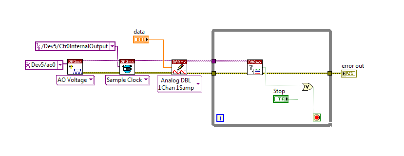
How can I pause and resume the analog output using DAQmx?
I use a DAQ hardware to produce an analog waveform. I would like simply to break the output of the wave and then resume where it left off. I use DAQmx and LabVIEW 2011.
I've seen examples that use a digital or analog break trigger, but I would take a break in the software only. How can I do this?
-Joe
Hi Joe!
I spent some time thinking about it and I realized that you can technically use a fundamental mission of the analog output, as you previously wrote that runs continuously. However, the generated output samples are controlled by the sample clock pulses, and can be manipulated to fit our needs "suspension."
To do this, we will need another counter task that generates a pulse train (see our examples of shipping under material input and output > DAQmx > generating digital pulses > generate dig Pulse Train - Continuous.vi) that stops and starts the user to choose. This can be in another quite VI or controlled by software. We will use this as the task of our output sample clock.
Then, the task of the AO, wire a constant to the sample clock source and select ' DevX/CtrXInternalOutput"based on the counter that you specified in the task of counter. You will need to choose "I/o name of filtration" and check the box that says "include advanced terminals' and right-click of the constant. See picture attached as a reference. In this way, the task of the AO is constantly running, but it generates only actually all data when the meter running task.
Let me know if you have any questions!
Have a great day!
-
poor performance analog output (error 200018)
Hello. I have a 6124 SMU Board with controller real time SMU-8102. the Council is speced to MECH 4 analog outputs. / s (one lane), but I have problems to operate at anything beyond about 500 kech. / s. I enclose my example below program. If I put the rate at 500 k, it works. If I put 1 m, it does not work and I get the error 200018 (DAC conversion attempted before Conversion data were available). I use the DMA transfer.
I also tried to increase or decrease the number of samples written by loop (between 50 and 300) and using a loop timed in labview real-time. That essentially gives the same result (sometimes I get error 200016 instead, "exceeding accuracy onboard device memory").
Because the controller is a dual core controller that do literally anything else (what I showed is the whole program, nothing else running), I don't know that I have some setting wrong software. I can't believe that this controller is unable to deal with this card. Does anyone have any suggestions on what I might try?
Version of LabVIEW is 2010 and DAQmx version is fairly recent.
Ok. I thought about it. Here's an interesting fact. At the rate of 1 MECH. / s, tries to write to 4096 samples each microseconds 4096 works perfectly well. But any attempt to write to 4095 samples fails! 4095 course is 2 ^ 12-1. It seems that DMA was running only transfers of 4 k at a time, so when he got 4095 samples, he was waiting for a sample more start the transfer, but at the time where he got this sample, it was too late. I changed DataXferReqCond property for "almost complete." Now, I can write about 150 samples at a time instead of 4096. Greatly improved!
Moreover, it would be really good to put in the text of the error message for the error 200018 so that others live several days tearing their hair like I did...
Thanks for the help
Daniel
-
Hello
My question is about the analog output (0 - 10V) of the myDAQ unit.
On the card, you can read:
"Overdrive Protection +-16 V forever."
Lets imagine the worst case: 0 V output DQA, but outside a battery or anything else is connected with 15 V to the analog output.
Fact an "unlimited" current in data acquisition or protection 'Overdrive' works here and the material is safe to destroy?
The background: I want to OD are protected from transient voltages and toilet on a simple zener diodes clip or a tvs diode...
Thank you all, Markus
Markus,
To use a zener diode as protection, you must also have an impedance of current limiting in series with the source against which you are protecting. The manual for the device of maDAQ indicates that the lines of the AO are pushed by OPA1642 op amps. TI the MSDS for this unit shows the current limiting internal ~ 36 my short circuit with Earth and a thermal shutdown circuit that tries to protect against the terms of overpwer.
However, under your 15 V battery, 11 V zener and 0 V programmed DAQ exit, the situation may be different. The current from the battery through the zener will be limited by the impedance of cables or any type of resistance on the line. This has no direct effect on the myDAQ device, but it will probably destroy the zener unless resistance limits the current to a lower maximum current nominal zener. As long as the voltage at the output of the myDAQ is lower than the internal supply voltage (+/-15 V), on the OPA1642 current limitation should apply. With 11V applied to the output and the value set to zero the device would probably be to try to sink the maximum current for-15 V power supply. Which translates to a dissipation of power of more than 900 mW, which exceeds the rated capacity of the op amp. Themal protection should, in principle, reduce the current to a level that does not exceed the thermal limit under development.
This test can be a costly process. The unit may be destroyed. Given that the maximum current specified for an analog output channel is 2 my and the maximum voltage is 10 V, I would consider a series resistance of perhaps 1000 ohms and clamping schottky diodes at the + 15 V and - 15 V power supply. This will limit the current to 10-20 my in all conditions you have mentioned and would also provide protection to the case where the battery is connected the myDAQ device is turned off. He alsoe does not care about the polarity of the external source. It will drop the output voltage according to the load impedance. If this should be used in a student lab, the calcualtion of this decline is something they should be doing anyway, and would be a small price to pay for protection.
Lynn
-
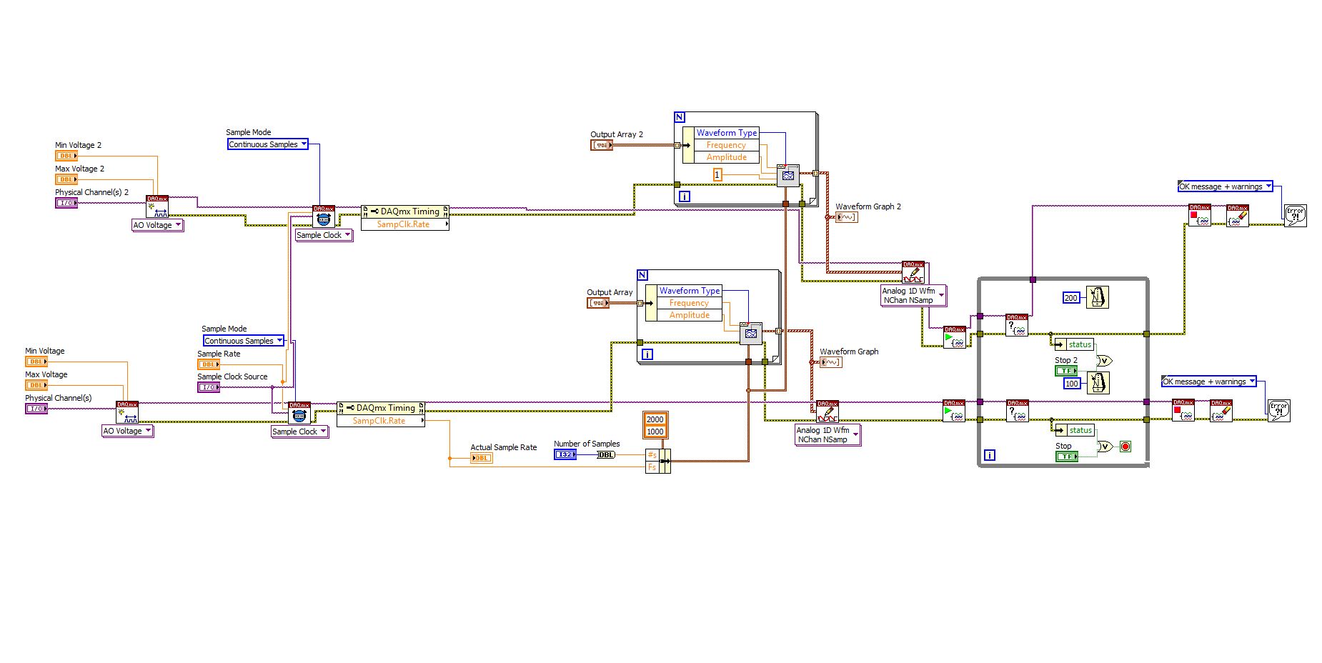
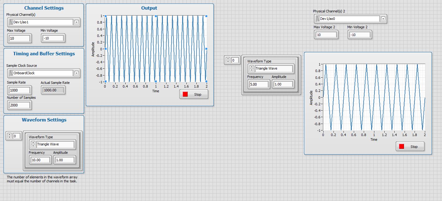
Generating analog output signals 4 with different frequencies
Hi all
I was trying to say to generate 4 different signals at different frequencies
1. first waveform is a sine wave with 5000 Hz,
2. other with 8000Hz,
3. third, one is a square with 25 Hz waveform and
4. fourth one with triangular waveform 50 Hz
all waveforms must be generated simultanoeusly.
I tried to generate with the task unique analog output and sample clock (clock rate is 100000). Cross in scope that I see only 5000 and 8000 Hz we generated correctly and the rest two waveforms show the incorrect frequency.
I guess that's due to the frequency of high clock to sample for more low frequencies for ex 25 Hz and 50 Hz. If I reduce the clock rate to get the lower frequencies properly so I can't generate frequencies higher correctly. (there's a clsh between frequencies and the clock frequency)
Is it possible to use DAQ board master sample clock and its magnitude downward revision (everywhere where it is necessary for each waveform separately) to generate all the signals at different frequencies at the same time in a single task?
Maybe you are looking for
-
How to block the photos in web pages
I use a very slow internet connection, this is why I don't want pictures in firefox 24.0 to show.
-
Drive HARD Win 7 recovery does not work on Satellite L750
Hello I have the Toshiba Satellite L750 with preinstaled win 7. I instaled the upgrade to win 8 (from dvd). After that I improve the MS site to Win 8.1 System. The system does not work properly (DVD is not recognized) so I have to install previuos sy
-
I have a Vista Home Premium 64-bit, Service Pack 2 Dell. He read/won't recognise no videos HD taken with my Canon camcorder HDD21/AVCHD (MTS format). Each attempt generates a message stating "Windows Media Player may not support the file type or th
-
BEI meinem iconia a3 - a40 micro sd schacht zu ist der. Warum
Hallo, ICH habe ein neues Iconia 10 A3 - A40. Warum ist der ´Micro zu SD Schacht, also kann keine Karte einstecken, oder ist das Modell then? MFG Wilfried
-
UPHClean not install on XPsp3, error message: uphcleanhlp.sys not found
I tried to install UPHClean - Setup.msi and she runs up until the last bit of the installation. He then told me that she can't finish and the installation will stop. The error message is: "uphcleanhlp.sys" not found. But I found myself in the fold