cFP-AO-200 analog output module (error-33180)!
Hello everyone
I use the CFP 1808 Bank as well as other such modules that HAVE 111 and enter I-110, I recently bought a Module AO-200 out of the currents of the order of 4-20 mA, I connected the module to the Bank and updated the device of the MAX Software, then I opened the Getting Started/Analog Output.vi leave examples in Labview to test 2011 map the VI returns an error with the code 33180 for me, I don't know what the problem is, but I tested the card with the MAX and wrote the values to it successfully.
Can someone tell me what is the problem with my VI
Thank you
I was able to reproduce your error. You must select 'All' in the Point IO Point field for this vi.
Tags: NI Hardware
Similar Questions
-
poor performance analog output (error 200018)
Hello. I have a 6124 SMU Board with controller real time SMU-8102. the Council is speced to MECH 4 analog outputs. / s (one lane), but I have problems to operate at anything beyond about 500 kech. / s. I enclose my example below program. If I put the rate at 500 k, it works. If I put 1 m, it does not work and I get the error 200018 (DAC conversion attempted before Conversion data were available). I use the DMA transfer.
I also tried to increase or decrease the number of samples written by loop (between 50 and 300) and using a loop timed in labview real-time. That essentially gives the same result (sometimes I get error 200016 instead, "exceeding accuracy onboard device memory").
Because the controller is a dual core controller that do literally anything else (what I showed is the whole program, nothing else running), I don't know that I have some setting wrong software. I can't believe that this controller is unable to deal with this card. Does anyone have any suggestions on what I might try?
Version of LabVIEW is 2010 and DAQmx version is fairly recent.
Ok. I thought about it. Here's an interesting fact. At the rate of 1 MECH. / s, tries to write to 4096 samples each microseconds 4096 works perfectly well. But any attempt to write to 4095 samples fails! 4095 course is 2 ^ 12-1. It seems that DMA was running only transfers of 4 k at a time, so when he got 4095 samples, he was waiting for a sample more start the transfer, but at the time where he got this sample, it was too late. I changed DataXferReqCond property for "almost complete." Now, I can write about 150 samples at a time instead of 4096. Greatly improved!
Moreover, it would be really good to put in the text of the error message for the error 200018 so that others live several days tearing their hair like I did...
Thanks for the help
Daniel
-
Analog output PCI-6251-DAQ-200016 memory overflow error
NI PCI - 6251 DAQmx, AIMD-752 motherboard, dual core processor, a lot of speed and the ram running WinXP Pro & LabWindows/CVI
get DAQ-200016 memory overflow error when I try to generate a signal of analog output with a rate higher than about 32 000 samples/second (?)
going on what? I have never seen it before. Is this a problem with the motherboard? "It's the same product on the CVI code example" \Cont Gen Volt Wfm - Int Clk\ContGen - IntClk.cws.
If someone has had this problem, and is there a solution?
Thank you
PS: full text of the message reads:
Measurements: On-board memory precision passing. Due to the limitations of system and/or the bandwidth of the bus, the driver could not write data to the device fast enough to track the rate of output of the device. Reduce your sampling rate, change the method of transfer of data (from interruptions on DMA), use a product with more on-board memory or reduce the number of programs that your computer runs simultaneously. Task name: _unnamedTask<1> Code of State:-200016
Well, I found my answer. For later use, Olivia NI Apps Engineering suggested I have change the mechanism of data transfer by this Knowledge Base document:
http://digital.NI.com/public.nsf/WebSearch/C326F7D33CA6DB0E86256DFE008043B7?OpenDocument
... so I inserted the line of code between the creation of the area of OCCUPANCY of the channels and set up the example of clock calendar.
DAQmxCreateAOVoltageChan( ...

DAQmxSetAODataXferMech(TaskHandle,chan,DAQmx_Val_Interrupts);

DAQmxCfgSampClkTiming(...
now, I am able to generate output to a 2.35 MS/sec... max sampling frequency not quite the 2.86MS / sec indicated in the specification 6251, but close enough that I'll stop complaining

-
AE CC Render error output module is not
Hi, I tried my best to find this answer on the forums, but couldn't find something common.
I have isolated two questions in AE CP where I can duplicate a render failed with this message:
After effects error: make error while writing file 'xxx '. An output module is not. The file may be damaged or corrupted. (- 1610153464)
This happens when opening an AE CS6 project and try to return a simple model with the single text layer and a moving mask. It happened just after my first round trip test with Cinema 4 d. I could RAM Preview layer the c4d in vain the output to Quicktime h.264.
I even tried a complete reinstall of AE CC. I have the plugins FxFactory Pro and MagicBullet Looks installed base, but are used because it is a model of 1280 x 720 single with a single layer of C4D. In addition, as I said it failed with the same error in the past CS6 files.
I don't know how to force disable them a plugin to test it, but I don't see how a unused plugin could cause a rendering to fail like this.
I'm on a new iMac 27 "(end of 2012)
Intel Core i7 3.4 GHz
8 GB RAM
NVIDIA GeForce GTX 680MX with 2 GB of VRAM
OS X 10.8.4
AE CC 12.0.0.404
Pilot CUDA 5.0.59
Thanks for your suggestions!
Matt
Todd thanks for your response! One of my friends told me this page as well and I was able to diagnose the problem. It turns out that it was a third party called AirServer app that apparently had the TCP conflict mentioned in your link.
I checked the Console and managed to find a message that is leading me to confirm the Adobe QT32 Server broke. After the scanning Activity Monitor for other applications using the same port my eye caught AirServer.
AirServer turns the Mac into a receiver AirPlay since an iOS device, so it makes sense that it uses QT on TCP.
Thus, smoking AirServer completely solved the problem and I will be informing their developers. Not even not uninstall it, it just could not be run when you run AfterEffects.
It's just strange to me that this does not affect the CS6 legacy.
See you soon,.
Matt
-
QuickTime export error: "an output module has stopped responding."
I feel an odd export error when I use the Quicktime codecs:
"After effects error: an output module is not responding." The file may be damaged or corrupted. You may need to restart After Effects. »
Similarly, Adobe Media Encoder crashes when Quicktime codecs. No program does any progress at all before the blocking does not happen. At this point, I have to manually "end task" to exit. In addition, it seems not to matter of what I'm trying to export. For example, in the SOUL, I can just try to convert one video format to another and do hang, so I don't think that the problem is due to a problem with the settings of the source or the effects. Also, I'm not all multiprocessing since I did not really enough RAM for it. Other work of output modules, so I export only image sequences for now.
System Specs:
Windows 7 64 bit
Intel i7 - 2600 k processor
8 GB RAM
GTX 580 GPU
Software:
Adobe CS6
AE Plugins include Tracode Suite 12 and optical flares
QuickTime 7.7.3
Any ideas on that? I have seen very few references to this error in other places and not really found a solution that seems to apply to my situation. Thanks in advance for your help.
Josh
http://myleniumerrors.com/2013/01/11/26-142-5/
Read it and the links that lead from there, then to understand what is blocking communication with QT.
Mylenium
-
read the output of a path of analog output current voltage
In DAQmx if you are unsure of the status of a digital output port, you can take a reading on this subject. When I try this on an analog output, I get an error. Is it possible to query the status of the output of an analog output? I realize that I could follow the State with a variable, but a direct reading would be really handy.
Hello, GIS.
There is no way to read the output in the AO modules without wiring physically the signal to a module to HAVE. You are able to use a variable to read the current value of the output, as you mentioned earlier.
Channels AO multifunction boards, however, can be read through tasks of entry by rounting in-house channel to read ao vs aoground.
Lisa
-
Read analog output channel value internally
According to this you can read the values of analog output of return without having to physically connect the wires.
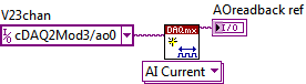
By using the technique described in the example given (DAQmx_Read_Output_Internal_Channels.vi) I'm reading a current area of OCCUPANCY on my compactDAQ cDAQ-9174 with a module of analog output current OR-9265.
The output channel is created in MAX and my vi can write values to him without problems
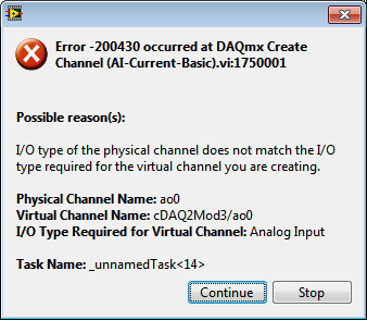
But when I try to create an analog input channel to read the output, an error occurs.
What I am doing wrong?
This is not supported by my hardware?
Or is the example given in the above incorrect link?
The example is 10 years old. Maybe, it does not work in LV2013.
Hi Jocker,
The link was not attached to your message, but I guess that's it: http://digital.ni.com/public.nsf/allkb/CB86B3B174763C3E86256FFD007A2511 as there the example of vi you mention.
The error you are getting is due to the use of the channel for analog output and trying to configure the task as a task of entry. You must use _aoX_vs_aognd as the channel of the task rather than on the output channel. This compares to the ground for the analog output values.
The NI 9265 is not on the list of the C Series modules that have internal channels:
So I guess that the module is not able to compare its output to ground. He would appear in the dropdown of the channel names if available.
Pete
Applications Engineer OR
-
Error 33180 - controlling a solenoid with FieldPoint
I use a LabView program to control a solenoid, giving an entry of 100 and 0 in the adjacent parts of a sequence of flat, using a writing FP (polymorphic) .vi and a constant Point IO FieldPoint for measurement of e/s. In the measurement and Automation Explorer, I can handle the cFP-PWM-520 module, successfully, giving 0 to 100 entries, but the solenoid does click not. The valve works physically, as I've tested before. When the LabVIEW program reached the part of the solenoid of the sequence of flat, he stops at the vi FP writing and gives me an error 33180 (the amount of data provided does not match the number of data elements required or the number of channels to deal with). I don't understand what that means or how it relates to the electrovalve. I joined the program (LabVIEW, 13).
Hello ksinks,
It seems that you have defined 0 to 100 as the index of your matrix constant as opposed to the real value in the table. in the constant matrix, the left field should remain as '0' If you try to pass a single value (because the tables are indexed from zero) and the value in gray on the right should be defined as 0 or 100 (or any value that you want to be passed in). Please try it and let me know if it works!
-
To input analog shutdown when the analog output is completed and synchronization
Hello
I'm trying to get my LabVIEW program to send analog output to a computer and read acceleration using the cDAQ-9184. Chassis output that I use is the NI 9263 and the chassis of entry is the NI 9234. I generate a signal of white noise using LabVIEW Express signal generator.
The first problem I have is the synchronization. I had an old VI that has begun to measure the acceleration just about a second after the entry has been given to the machine. I used the LabVIEW tutorial on how to sync the analog input and output, only to discover that it does not work with two different hunts. Then I found another tutorial that shows how to synchronize different frames between them.
The second problem is the cessation of the LabVIEW program. What I want to do is to generate the signal and then simultaneously send and read the input and output analog, respectively. It is because I don't want a phase difference or any shorter signal for a direct comparison. But as soon as the signal is sent to the machine, I want the entry to stop analog playback and then then the LabVIEW program must stop. I want to be able to choose any length of signal to be generated and stop as soon as the entire duration of the signal has been sent to the machine.
I tried 'DAQmx stop', "DAQmx Timer" and 'DAQmx's task made?' and none of them have worked for me. It is also my first time on a forum posting, so I hope I gave enough information. I enclose my VI as well. The VI shows I read an entry for the analog input voltage, but I am only using this to try to get to the work programme.
I'd appreciate any help I could get.
Thanks in advance
Peter
Hi Peter,.
I have some recommendations for you that I think you will get closer to your solution. First of all, I assumed you meant that you had 1 chassis (cDAQ-9184) who had two modules in it (NOR-9263 and NOR-9234). My next steps are based on this assumption, so if it's wrong, please let me know.
For your first question about the synchronization, the code you provided is very close to what you need. You need to do, however, implement architecture master/slave for startup tasks DAQmx functions. To do this, you can add another frame to the flat sequence structure and put the master start task (input voltage) after the start slave (output voltage) task.
To manage your second question and that the program ends at the point where you, the first step is to get rid of all the logic that you use with the local variable of length of time. Rather than use this logic, just wire the node "task performed?" of "is task performed?" operate to stop the loop. This will cause your loop to stop as soon as the signal is sent to the machine.
I have some other recommendations for you that will increase the performance of your program:
(1) rather than writing on file inside the last loop, you can use the DAQmx Configure Logging (PDM) .vi. You will place this VI between DAQmx Timing.vi and DAQmx Start Task.vi to the task of the analog input voltage.
(2) after the last while loop, you want to stop the task and analog outputs as well with another DAQmx stop Task.vi.
(3) rather than using a local variable for the entrance of displacement and wiring it in the DAQmx Write.vi, you can wire directly from the output waveform of the wave to build function node.
That should help you get started in the synchronization of these tasks.
-Alex C.
Technical sales engineer
National Instruments
-
How can I check if the counter entry is synchronized with the analog output?
Hello
I'm working on an application for counting photons. I use two channels of analog output on a PCI-6713 card to send a frame model to a set of XY scan mirrors. I then a photon count unit that emits a TTL signal when the photons are detected as a result of this raster analysis. I then use a surfboard USB-6211 to count the edges on this TTL signal.
I have problems that seem due to synchronization problems. I use the sample AO on the PCI-6713 card clock like the door of my meter on the map USB-6211. I use a trigger to start digital to analog output and a trigger of arms for the entrance to counter early. Is there a way to check that the analog output and counter entry of start of operations at the same time and are are synchronized? I basically want to monitor and compare the ao real sample of the PCI-6713 card clock door signal used by the jury of the USB-6211. I was able to export the sample AO clock and watch it on my oscilloscope, but not the signal from the door of the USB-6211.
Thanks for your help,
Brian
Update... It turns out that there is no problem of synchronization between my meter input and the analogue output. There was a difference of impedance when I connected my unit of counting photons to my USB-6211. This caused an error variable count rate. After accouting for this shift, the problem disappeared.
-
generate a square on the analog output wave
I use a PXI-6229 DAQ card and I need to generate a square on ao0 wave. I'm programming in c# and have found an example of the expedition, which generates a sine wave. I need to be able to modify the function generator that was provided with the example of the expedition to produce a square wave 7.2 kHz with duty cycle of 50% and 2 v peak-to-peak. I enclose the code generator to function.
Thank you
After a lot of trial and error and adapt the example to generate a sinusoidal signal, I have the solution to generate a square signal of analog output. I enclose the code.
-
variable phase shift between two analog output signals
Hey! I would drive two different piezo elements with an sine - / square signals and have a phase shifted output signals. After some trail and error, I was able to get a second analog output on my card PCI-6221 (using LabView 8.2) also allowed me to have different amplitudes for both signals. However, I could not output signal having a frequency different and most importantly to my request to have one of the signals variably shifted phase.
Thanks for the very useful suggestion. I have attached the file .vi installation I've run so far.
Hello!
A way to generate waveforms is using the analog waveform Toolbox. I created an example VI that is attached and that shows you a way to use the base generating function VI. I saved for LabVIEW 8.2.
I hope this helps!
-
Acquisition of multiple simultaneous analog output data
Hello, I'm doing a program when a user telnet to my computer and labview will recevie provided cn and analyze. then, he deciphers the emssage find what analog output it trying to change and then change it. I all the work, but I get error 50103 who say I can't have 2 screws DAQ assistant express running simultaneously. I want to have 2 different signals on A0 and A1 on my surfboard USB-6281. Is this possible? Thanks in advance. BTW im using labview 8.2
The vi in LV2009 is attached. I did the mods I had described. It should be a beginning. Modify if needed.
-
Analog outputs with different time scales
I use products AO of a card PCI-6731 for an application scan head and I have some difficulties to achieve peak performance, that I need. I am contolling the map with nidaqmx drivers in c ++
Basically, an output controls scanning in the direction Y (which is a line of scanning and is very fast) and the other in the X (increment once per scan line, so much slower). The complication is that both exits start at an external trigger, because positioning is synchronized to a separate data acquisition card.
Now, what I do is:
-write the scanline for 0 output waveform
-set output 1 to a given position
-say next Trigger output card
-hangs at the end and stop tasks
What I really want to do, it is just tell him to start with on each external trigger output waveform of scanline 0 and output 1 increment to the next position. So I could do a complete 2D scanner with a minimum of control software.
Any ideas on how I could best achieve this? My understanding of the nidaqmx drivers I don't see an elegant way to do it.
I could potentially do some operations on the done callback, although it makes me a little nervous because the control PC running windows, it is not a real-time operating system.
Hmm I do not know exactly but there are a couple of things (it is close)...
The output frequency of meter in your example 5 MHz (20 MHz, 2 high ticks, weak 2 ticks), which is faster than holders 6731 for a sample clock. I thought that this would have given a material error... are you looking for errors once the task runs (for example using DAQmxIsTaskDone)?. There is a DAQmxCreateCOPulseChanFreq if you want to set the clock frequency directly (it will use the appropriate default internal time base).
The task of counter generates 1000 pulses per trigger, is what determines the number of samples generated by the trigger (I assume that you want it to be 1024 aka "numSamples").
The analog output task must either use:
(1) calendar continuous if the output will repeat indefinitely as several triggers are acquired.
(2) finishes pitch (N * numSamples) samples where N is the number of lines that you want to exit and numSamples is the number of samples per line. In this case, the task will end once the lines were triggered.
Best regards
-
Simple examples of analog output USB-6343
I've tried passing by 'find' examples and does not know how to find what I want.
I'm doing a simple analog output on a USB-6343. Examples of waveforms say they work with the USB-6343, but I really don't want a waveform, just analog of output does not exceed 10 Hz speed of renewal. Some of the more simple examples show that they work with the pcie-6343 but do not list USB-6343.
I worked with USB-6009 in the past, but when I try to use an analog output task that uses 1 sample on request, I get the error "not buffered operations clocked by the hardware are not supported for device and channel type.» Set the size of greater than 0 buffer, do not set up the timing of the sample clock or the value Type of sample On Demand time"
I tried samples N, 100 samples to write to 10 Hz - the same error. Samples of continuous - same error. 1-sample - timed HW - same error.
There is a series of examples of I/O for the X series? Is it possible to search the device examples rather than go through all the examples and by checking the list of devices individually?
Is 'size of the buffer' the 'writing samples"in MAX?
After contacting the support I was provided with the names of the more simple examples for analog i/o:
Analog output-Gen power Update.vi
Analog Input-Acq & chart voltage-Int Clk.vi
They are found in the getting started screen of
Click 'Find examples' near the lower right corner
Filter the results to material by clicking on the menu drop down for the material in the lower left corner and selecting USB-6343 (only connected equipment will be displayed)
Don't forget to check the box "limit results to material" below.
In the center pane, double-click 'Material Input and Output'
Double-click DAQmx
Path for the analog input - double-click Acq & chart analog measures - double click on tension - tension-Int Clk.vi
Double click on analog generation - double click on Power - Gen Update.vi of analog channel output voltage
The examples are for the single data point. Samples and exit multiples are produced by putting the writing or reading VI inside a loop. The beginning and the clear functions should be out of the loop.
Additional information, I need technical support was how material-filter results and identification of more simple examples which were not obvious from the examples of names.
Maybe you are looking for
-
Hey there, Currently, I use a Macbook Pro (mid-2012) with OS X El Capitan with Itunes v.12.4.1.6 v.10.11.5 I would get all my playlists to be in list mode and I was able to change half of them before the recent updates (v.11 or v.12 I think). Now, I
-
Everything I did was done with my right hand, the font is so small I can't read at all. When I did it using Windows there is a box in the upper right corner, I can click on and it lets me realign my font size to 100%. I can't find such a tool on Fire
-
Satellite 2405-201 will not start a windows
It's a very strange problem. Well everything worked well until I have shut it off. After turning the power on I had a Toshiba screen with the start menu for a few seconds and after that I got is a black screen with blinking cursor. Keyboard does not
-
Update blackBerry Smartphones BlackBerry Device with Mac
Hello I have three questions about my BlackBerry "BOLD": 1.) as a Mac user I want to update my device software. However I don't find this function in the BB Desktop Manager for Mac. Any advice? 2.) I need to add some languages like Chinese or Japanes
-
Skype stops when I make a call? Running on windows 7 and it told me that another program has led to close?