PXI-1044
I am currently working with the NI PXI-1044 chassis. Whenever I turn on I meet a solid red light and fans to remain in high mode. I looked in the manual and all she's talking to a flashing red light. I wonder if this can be fixed with a simple exchange of a new part and not a swap of all of the module.
Thank you
TeddyEE
Thanks for the quick response. I actually found the question. Apperantly that fans have been changed earlier due a fanand sqwaky replaced with a type that is not compatible. It turns out that the fans who were in it were a wire (pos, neg, and lock the rotor sensor). The fans who had to be installed should have been a wire (pos, neg tacho sensor).
Your response was on the spot. Thank you for your help.
TeddyEE
Tags: NI Hardware
Similar Questions
-
PXI-8250 in one frame other than the 1042/1045 or PXI-1044?
The PXI-8250 will work at any level in one frame other than the 1042/1045 or PXI-1044?
Hi djfrye.
The PXI-8250 can only be used in the 1042 / q 1042/1045. It will not work in the PXI-1044.
Good luck with your application!
-
Synchronization of multiple unit with the PXI-1044-6250 M-6143S
Hi all
I have a problem with several device synchronize with my PXI system: when starting a measurement, the devices do not start at the same time despite using a trigger to start. The delay in the start time varies randomly between 150 nanoseconds and about 80 milliseconds.
My PXI system consists of the following:
- Controller PXI-8108
- Chassis PXI-1044
- 6 * Series S PXI-6143 (Slots 2-7)
- 1 * Series PXI - 6250 M (8 slots)
The software in use is LabVIEW 8.2.1, NOR-DAQmx 8.9 and MAX 4.5. "The trigger line routing" is set to "Dynamic" for all 8 lines.
I created 3 tasks in the attached VI: task 1 ('Drehimpulsgeber' = encoder, 1 channel, rate: 1.25MS / s), task 2 ("Heißfilme 1-8" = hot-film probe No. 1-8, 8-channel, 250 ksps through rate / s) and task 3 ("Heißfilme 9-16" = hot-film probe No. 9-16, 8 channels, rates by way of 250 ksps / s). 3 tasks are expected to start at the same time acquire the analog voltage by pressing the button "Start". "." As the trigger for the beginning, I use a digital pulse created on/PXI1/PXI_Trig0.
After reading samples, the first timestamp recorded for each task is retrieved, displayed and the delay time is calculated (see boxes 'Start time' and 'Time Delay' on the front panel).
How can I optimize to synchronize the start of all three devices without getting this random delay?
Thank you in advance.
Kind regards
Matze
Hi MatzeK,
Here's another one. Could you please try this too and send me information on success?
TomBaum
-
PXI-13 6133 in a single task OR DAQmx?
Is it recommended to use the PXI-13 6133 in a PXI-1044 + PXI-8106 in a single task?
Installation program:
PF0 trigger every 40ms
Sample PF8 103kHz clock
samples of 1020 per channel
Hello Jainsch,
just a little addition:
Please set the speed of the fan in the back to 'HIGH' and insert a Slot-blocker in all empty slots to improve airflow (cooling).
http://sine.NI.com/NIPs/CDs/view/p/lang/de/NID/206303
Kind regards
N. Ralf
-
"error-200621" trying to generate 20 kHz sinusoidal aboard the AO0: 1 of the PXI-4461
Hello!
I am getting a-200621 error trying to generate a sine wave of 20 kHz the signal output of a Council of PXI-4461 0 and 1. The signal is generated for a few seconds, then the error «on-board device memory overflow negative...» "happens! Why? and how can I avoid it?
If I'm generating 1 kHz or using a single channel, all is well!
I joined the vi as well as the error message.
Here is the configuration of my system:
LabVIEW 8.5
PXI-1044 chassis with 14 locations and MXI-4 Council (optics) to communicate with the PC:
-Connector 2: OR PXI-4461
-Slot 3: OR PXI-4461
-Slot 4: OR PXI 2561
Computer:
-Intel Core 2 Quad Q9400 2.66 GHz CPU
-3.49 GB of Ram
Thank you in advance.
Frédéric
Hi Peter,.
The issue is resolved in fact to increase the number of samples that are written in the buffer!
Thanks to you and Laurent!
Frédéric
-
How to set up the PFI lines as input to PXI-6713 module
Hello
I have 6713 PXI module in my chassis PXI-1044. I have configured the PXI-6713 module to geneate some analog signals to my Board of Directors.
Council inturn process this analog signal and answers in return the status signals through a registry to the Board of Directors. In my application, the status bits in the register state of the governing body are mapped on the PFI 0:3 bits of the PXI-6713 (pins 11,10, 42 and 43) module.
My query is how can I configuration lines PFI as 6713 PXI module entries to read these status bits?
May be less than the explanation could give you little more information w.r.to my request.
When I use NI USB - 6008 module to read the same bits, because this unit has 12 e / s digital, I was able able to read the status bits in the last 4 digital lines by setting up those digital lines as input.
In the PXI-6713 module, I have only 8 digital lines. These 8 digital lines I used to send digital signals to the Board of Directors. I find myself with no digital i/o. Therefore, I could not use these digital lines. I'm left with only one option to use. Joana re PFI lines. Also the bits of status in the axis of the room are mapped such that the bits can be read through the PFI lines.
I was wondering do we have any example code to use inorder to read these status bits to the Board of Directors using the PFI lines.
Please let me know if you need more information to help out me.
Thank you.
Hello
When using the PFI PIN as input, you can individually configure each PFI for edge detection or level and the selection of the polarity. This information of PFI are referenced in the manual of Series DAQ Analog Output on page 6-1 (http://www.ni.com/pdf/manuals/370735e.pdf). Unfortunately, the PXI-6713 PFI lines are able to time a signal input and output for functions, AO or counters/timers. The ability to create static DI of the PFI lines is not available for the PXI-6713. However, some cards have this capability. The latest National Instruments products with PFI lines have the option of setting as PFI lines:
- Static digital input
- Static digital output
- Input signal of sync for functions HAVE, AO, DI, or counters/timers
- Output signal of the calendar functions HAVE, AO, DI, or counters/timers
(http://digital.ni.com/public.nsf/allkb/14F20D79C649F8CD86256FBE005C2BC4)
When the static value such as DIO, PFI lines are assigned to a different port (for example. PFI0-7 is Port1). More details on this subject can be referenced at:
http://digital.NI.com/public.nsf/allkb/DA2D3CD0B8E8EE2A8625752F007596E1
http://digital.NI.com/public.nsf/allkb/862567530005F09E8625677800577C27
-
PXI-2530/2567/2593 Instrument map self-test
Hello
We will use the PXI-2530,-2567 module, &-2593 instrument cards in our chassis PXI-1044. We use LabVIEW software coding ATE platform. We would like to perform a self-test on the cards before the measures of the object to measure. Do you have any documentation that will support this task? The approach to check the functionality of card better by querying the records of the State of the map? In any case, I can't find any information online about this topic.
Thank you!
Dan
Hi dan_tuq,
That's all! simply provide a valid handle for each call of niSwitch Self-Test VI. Good luck!
Kind regards
-
PXI, switching boards causes the boot can´t pc
Hello
I pxi-1044 with some pxi cards (pxi-4065 / 6509 / 2529 / 8431 / 8432 / 2576 (3 borads))
and the pxi-8310 controller.
When the system has been configured for the first time, it works well.
but 2 of the borads (pxi-8432 / pxi-2576) must slot interchange (due to problems of space with their own, conectors)
When the system power, both led (on pxi chassis) and together (led controller), but windows xp does not start,
Led CONTROL switch to and restart the computer. over and over again.
I remove all the advice and check that all are recognized through MAX except the two planks of switching.
Change to a different location (never used) and the look of system work ok, pxi-8232
this Council is recognized.
What is the correct procedure to exchange some tips when MAX has a previos configuration?
I would use the slot machines that I have problems with, is it possible?
Thank you
Insteading of delete here or trying to remove, we can always Dispatcher threads.

Suite here.

-
SATA: ERROR: giving up on the I/O transfer [0 x 35] 0
Wrote the code to perform a very simple text on the same file over and over again write on a loop of 10 seconds approximately. The code was written using all the tools of stock. The above error msg would appear and continue to occur at each attempt to write. The drive has been formatted by using the format datalight reliance system. Chassis: SMU 1075, controller: SMU-8133. Tried a new contoller and the hard drive with the same results.
Reformatted the HD in FAT32 and the problem disappeared.
The code opens and saves in the same file each time. A run that same code on frame: PXI-1044, controller: PXI-8110 with reliance as fast as 1ms without any problem.
The code is a while loop with write in text file with encoded text hard and hard-coded file location with wait 10 sec. The code will run for several loops and the error happen to apparently randon times.
I restarted the report this morning after tests were completed and the report came back different from the previous. The report today is the FAT that is consistent with what we have formatted days ago.
-
How to synchronize the start of IT and relaxation the Scan list (DAQmx Switch)
Hello
I want to measure samples of N to the AI0 of Council NI PXI 4461. The measurement starts on a rising edge of a digital triggering provided to the PFI0 of the same Board. The measure is configured with samples of N/2 pretrigged. So far, everything is under control...
Using an NI PXI 2567 Board, the signal applied at the entrance the 4461 (AI0) switches between a V2 and V1 signal. I would like to synchronize the switch between the two signals with the trigger signal applied to the input of the PFI0 Governing Council 4461. In order to obtain samples of N/2 of V1 and V2 samples N/2. Synchronization of 1 to 5 ms would suffice!
My question is how to synchronize the start of acquisition of AI pretrigged of 4461 with the switch control given by the Council of 2567?
Thank you in advance for your help...
PS: the configuration of the system is:
-LabView 8.5
-Chassis PXI-1044
PXI-4461 on slot 2
Module 4-slot PXI-2567
Hi Frederic,.
I came back to this recently and used the following examples to run the desired synchronization.
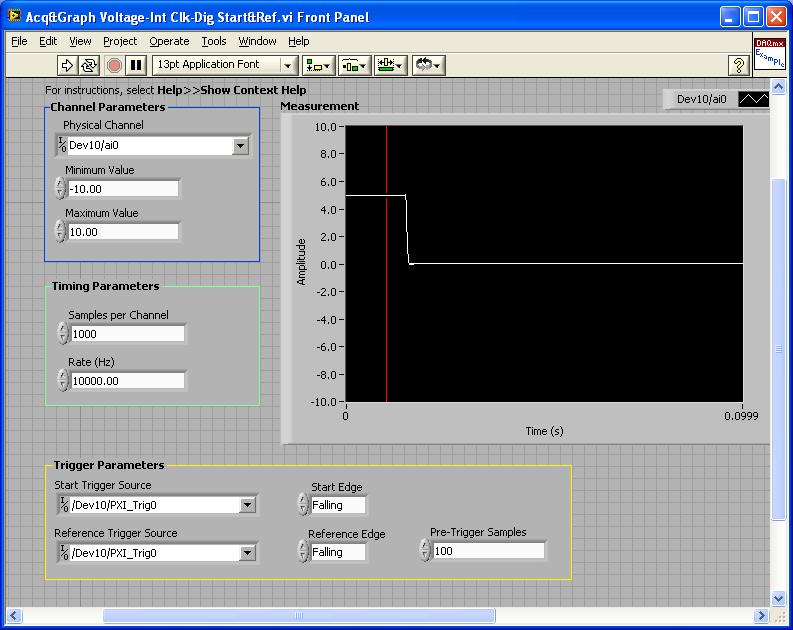
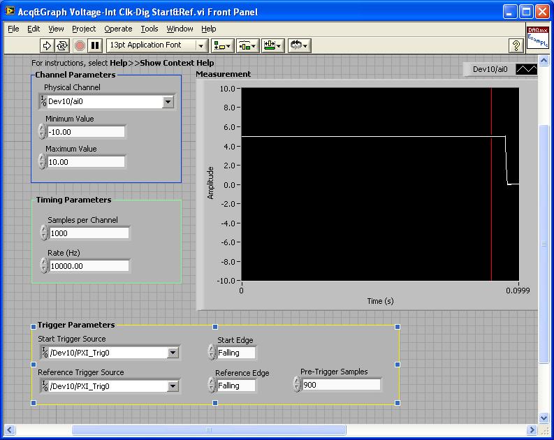
PXI-4461: Acq & graph tension-Int Clk - dig Start & Ref .vi
Samples per channel = 1000
Rate (Hz) = 10000.00
Start the trigger Source = / [name of the instrument DAQmx] / PXI_Trig0
Onboard start = fall
Reference Source Trigger = DAQmx Device Name] / PXI_Trig0
Reference edge = fall
Trigger samples = Variable (100, 500, 900)
PXI-2567: Switch Scaning-SW Trigger.vi
Advance the output terminal full = / [name of the instrument DAQmx] / PXI_Trig0
Scan list = / [name of the instrument DAQmx] / ch0-> com0.
Scan list = / [name of the instrument DAQmx] / ch1-> com1;
Hardware configuration:
The PXI-2567 module controls an external relay that switches between the voltage of 5 V on ch0 and ch1 0 V.
The PXI-4461 connects to the COM of the external relay and therefore reads 5V when ch0 is connected; 0 v when ch1 is connected.
Procedure: The above examples are used in the following procedure.
1. run the PXI-4461 VI. A start trigger (falling edge) is necessary to start collecting samples before firing.
2. launch the module, PXI - 2567 VI. When ch0 is initially (and immediately) on com0, a trigger is sent to PXI_Trig0. The PXI-4461 will begin to acquire samples before firing.
3. - click on the "Connect to the next" button on the front of the PXI - 2567 VI module. This sends a trigger to entry software for the PXI-2567 module and the transitions of the scan for ch1-> com1 list. Once the PXI-2567 module remains (debounced), advanced complete relaxation is sent on PXI_Trig0 for the PXI-4461. The PXI-4461 will begin to acquire samples after outbreak.
Note: Instead of the trigger of the software entry, an external input trigger can be used (e.g. PXI_Trig1).
Results:
> Before instant release of samples = 100
Delay is caused by the time of actuation of external relay.
> Before instant release of samples = 500
Delay is caused by the time of actuation of external relay.
> Before instant release of samples = 900
Delay is caused by the time of actuation of external relay.
I hope that the attached screws and the explanation above helps you and/or other customers who have this problem.
Best regards
Chad Erickson
Switch Product Support Engineer
NOR - USA
-
Hallo,
I use the following system:
- OR PXI-1044 with controller NI PXI-8109
- OR PXI-2564 switch module to turn on the monitor of my test device
- Data acquisition multifunction NI PXI-6259 to measure the signal that responded to the questionnaire jump
The two cards are the same - PXI trigger bus. For both, PXI-2564 and PXI-6259 I use DAQmx to set the reading and writing of the channels.
Now, I want to measure the time between the digital output, my unit turns and the analog input, which measures the response of my system.
I can't do work by myself, please help me!
I thank Ludwig.
Hi Ludwig,.
If you can't give us any VI we have difficulties with to help you.
Because I Donat knowledge how your program is mounted it is not easy to know where you should enter signals.
Here's a question similar to yours:
http://forums.NI.com/T5/LabVIEW/best-way-to-measure-time/TD-p/178704
and 2 external links:
http://www.ehow.com/how_8698983_measure-time-LabVIEW.html
http://objectmix.com/LabVIEW/385152-how-can-i-use-LabVIEW-measure-time-between-analog-pulses.html
-
Read Calibration expiration with Labview
Hello everyone,
I found a way to read the configuration of my PXI-1044. I would read the section external calibration of the Calibration tab in MAX for my PXI-5114 and PXI-4065 (last calibrated and recommended the next Dates of calibration) using Labview to read. The preferred format, I'm looking is similar to the configuration of my PXI-1044 which retrieves data in a format delimited by tabs. Thanks in advance for any information that can throw this forum on this topic.
Kind regards
Scott
Hi Dennis,
Thank you for your most recent reply.
Thanks for the vi. I tried on one of the systems and other that it could not find the Initialize.vi, I replaced with one that is the measure of e/s > System Configuration, it will do the job and data retrieval will not be a problem.
Many thanks for your efforts to help me better understand this particular function and please pass the file. I consider this closed post.
Kind regards
Scott
-
Meine question werden die Erfassung von Daten binaren. Meinen system representation: Ich habe in LabVIEW ein Programm is mit dem ich binare Eingange einer ausgebe und die zurucklese der SPS exits SPS. Für die Eingange sende ich einen Wert as Kanal jeden binaren, zB DI1.1, DI1.2 etc... uber eine task und für die Ausgabewerte zu injured ich die Binarwert zB DO1.1, etc... Do1.2 back. Dies zu tun habe ich eine Labview environment die mit i/o Karte PXI-6528 clear sind (was 3) die in einem Gehäuse PXI-1044 has die Schnittstelle zu der SPS werden. Die Eingangskanale der values werden in einer Excel-Datei form einer Tabelle geschrieben und die Excel-Datei wird in eine Datei TDMS transformed. Die TDMS-Datei wird von einem selbst Ende VI read und die Eingangswerte werden über eine write task zu der SPS then. Der zum read of the injured ich der Ausgangskanale die Ausgangszustande über eine Lese SPS status task back. As soon as die task State (Schreiben und read) sind, kann ich das Programm exit. Nach dem exit wird die TDMS Datei in eine Datei Excel umgeschrieben. Die ist Excel-Datei abgelegt und auf meinen Rechner available. Write Lese und die task a TDMS file geschrieben werden durch ein journal die der SPS values further. Meinen problem: in der Excel-Datei bzw. TDMS Datei werden die Eingabewerte einen single binaren Eingangsport (8kanale) von einer der drei entry maps Halogen geschrieben wird (Werten werden in zwei Zeilen geschrieben) was seltsam scheint ist das für die other Eingange same werden die Karte der normal geschrieben (nur eine line auf, wie es soll breast) question 1:-Ich finde nicht raus warum sharp values doppelt geschrieben werden, kann mich jemanden helfen? Man hat mir die TDMS Datei zu me, question 2 recommended:-weiss wie man a TDMS file auslest someone? ICH habe diesen link found aber die .exe Datei lasst sich nicht installieren. http://zone.NI.com/DevZone/CDA/EPD/p/ID/2944 Anbei find you are a screen shot von meinen Programm Danke im Voraus für die Hilfe für die ich bin nicht Deutsch Sprachfehlern Sorry.
Hallo,
Meine question werden die Erfassung von Daten binaren.
Meinen system representation:
ICH habe in LabVIEW ein Programm is mit dem ich binare Eingange einer ausgebe und die zurucklese der SPS exits SPS. Für die Eingange sende ich einen Wert as Kanal jeden binaren, zB DI1.1, DI1.2 etc... uber eine task und für die Ausgabewerte zu injured ich die Binarwert zB DO1.1, etc... Do1.2 back.
Dies zu tun habe ich eine Labview environment die mit i/o Karte PXI-6528 clear sind (was 3) die in einem Gehäuse PXI-1044 has die Schnittstelle zu der SPS werden.
Die Eingangskanale der values werden in einer Excel-Datei form einer Tabelle geschrieben und die Excel-Datei wird in eine Datei TDMS transformed. Die TDMS-Datei wird von einem selbst Ende VI read und die Eingangswerte werden über eine write task zu der SPS then.Der zum read of the injured ich der Ausgangskanale die Ausgangszustande über eine Lese SPS status task back. As soon as die task State (Schreiben und read) sind, kann ich das Programm exit. Nach dem exit wird die TDMS Datei in eine Datei Excel umgeschrieben. Die ist Excel-Datei abgelegt und auf meinen Rechner available.
Write Lese und die task a TDMS file geschrieben werden durch ein journal die der SPS values further.Meinen problem:
in der Excel-Datei bzw. TDMS Datei werden die Eingabewerte einen single binaren Eingangsport (8kanale) von einer der drei entry maps Halogen geschrieben wird (Werten werden in zwei Zeilen geschrieben) was seltsam scheint ist das für die other Eingange same werden die Karte der normal geschrieben (nur eine line auf, wie es soll breast)
Question 1:
-Ich finde nicht raus warum sharp values doppelt geschrieben werden kann mich jemanden helfen? Man hat mir die TDMS Datei zu me recommended,Question 2:
-weiss wie man a TDMS file auslest someone? ICH habe diesen link found aber die .exe Datei lasst sich nicht installieren. http://zone.NI.com/DevZone/CDA/EPD/p/ID/2944 Anbei find you are a screen shot von meinen ProgrammDanke im Voraus für die Hilfe
Sorry für die Sprachfehlern ich bin nicht Deutsch.
-
I just don't understand?
What is the point of the feature to import/export of Configuration MAX and why my version of the installer allows (not need) to set?
We have a project that has been developed on a chassis NI PXI-1044. He now resides in a configuration management system, and sometimes we want to remove to make changes and build on a system that now knows nothing about PXI/chassis/controllers/etc, etc. In fact we have more material. But this Configuration hardware option within the construction of the Installer seems to require a configuration by MAX file on the host system used for the generation of the project. Is no longer the PXI-1044 chassis but another PC altogether.
Why is this hardware configuration option exists? What is its usefulness when it comes to the installation of an integrated (such as an installation program) project. Why I can't live without it?
It is perhaps a fundamental issue, but it makes no sense to me. I come from a background of the conventional script-based programming (C / C + c++ / Ada etc.).
Thank you.
The hardware configuration is not at all unique to LabVIEW and you also use it with all the other languages where appropriate. The configuration includes the names of devices, custom scales, tasks, etc. Include you the configuration that you have created on the original pc or recreate it on the deployed pc. If you have not used MAX for any configuration, so you do not need to export/import but correct detection name, scales, etc. have all be integrated into the program itself.
-
Some or all of the requested samples are not yet acquired: API change responsible?
My Delphi program, which works very well under NOR-DAQmx 8.9.0f4 on a set of material, fails under 9.0.0f2 on what I received insurance material is equivalent. The error is «some or all of the requested samples are not yet acquired...» ». This happens even to slow scanning rates, and coming to suspect that the API has changed subtly in the transition from version 8 to 9. What is the probability is it? Now that I have access to the source code on the new hardware (NI PXI-1044 with computer integrated PXI-8110) is there something I can do to check this?
Hi Francis,.
Your program still calls DAQmxCfgDigEdgeStartTrig() for all the tasks of the slave? If you do not do this, the devices are beginning to acquire data at the same time, and since you pass 0 for the timeout parameter to DAQmxReadBinaryI16(), out-of-sync devices could certainly time-out errors.
In addition, you must ensure you start the slave devices before the master device, so that they're already waiting for a trigger at the start of the master device.
Brad

Maybe you are looking for
-
OfficeJet 5740: Officejet 5740 does not print from pc
I just bought an officejet 5740 and I can print from Notepad, but nothing else on my computer. Not even the test page. I tried the word excel adobe via ethernet and cable usb on windows 10 64-bit and ubuntu 14,04 32 bit on different pc, modified driv
-
Management of multiple access points 1220 and 1230
Hi all Is it possible to manage several 1200 Series APs in the same (or similar) independently, which can a WLC for most configuration changes but management and monitoring capability would be nice. Thanks in advance. All the answers have been evalu
-
Oracle of the MAF: Incorrect alignment in the user interface
Currently working on the MAF to design an application. but I am unable to align the fields in perfect order... I described the width of each field to be the same. but still do not get the same alignment for all fields when folding of the emulator. Pl
-
Action script to animate canvas CC?
As much as I know animate canvas works only with Java script. Just after that, Adobe introduced its snippet and says that it is designed for people who do not want to write code, you are asked to read some obtuse stupifying article on writing code.Al
-
Please cancel my subscription online from Adobe for 2015-2016-refund code my BMO MC
Please cancel my subscription online from Adobe for 2015-2016-refund code my MC BMO.Julie Wood. Glenforest Secondary School