PXI-5421 generating an arbitrary signals on the fly
I have a card PXI-5421. I need to generate an arbitrary waveform with different frequencies. I need to have a trigger to switch between Forms of waves of different frequencies. I use the script to do this. I'm not able to update the frequency of the next wave on the fly without stopping the program. In other words, can I download signals in real time? The code is attached.
Hey Kakrott,
You should be able to achieve this with your PXI-5421. The example of 'switch between the waveforms FGEN"in the examples of LabVIEW makes something similar to what you're trying to do. As explained in the documentation: "this example shows how to switch between two different wave forms while generating, using updated data every time." This example uses a trigger to change what waveform is generated.
Tags: NI Hardware
Similar Questions
-
Unable to send arbitrary signals of CC. Help. Please, I beg you.
Hello people,
I am a student of Btech working with Labview 2013. I managed to generate an arbitrary Signal through Labview 2013 version for my project. Now, I need to send the signal to Agilent 6642 power supply dc to ampilfication and it will be used for my experience. I am facing problem here.
I use GPIB USB HS to send the signal, and when I send commands * IDN, is successfully reading and writing, which means I have all my software and drivers installed perfectly. I have installed in my pc control expert and NI MAX.
I did a program (which is attached) in labview and the GPIB seems to read (signal ACTIVE/Green shows when it is executed).
But I do not see it in the oscilloscope (Tektronix TDS 2024 B) which means something's wrong here. I need to see the signal as shown in the attached picture.I am new to labview and don't know much. Please help me with the Labview program as I want to see the signal in the oscilloscope as well.
If a command is needed, let me know the order.
I'm stuck. Help, please.
Thank you.
-
Hello
I would create a program that simulates the signal given by the contraction of a heart Chamber. It should be periodic with an adjustable frequency and amplitude. I use a structure of the event with a time-out interval equal to the time interval of the signal and a block "simulate arbitrary signals." The problem arises when the signal trace because the graph shows all forms of wave side by side instead of not not been zero only after than all of the time interval. You will find attached an example of signal I would get and that I receive and the labview VI.
I hope my question is clear, thank you in advance for the help.
Federico
So, you want something like that?

-
generators of PXI arbitrary signals compatible with the generation of ssb vi
There of SSB generation vi, what Arb. People of waveform. will work for the PXI system? 54xx?
Here is a list of our arbitrary signal generators that this vi should work with:
NEITHER 5411, 5412, 5421, 5432, 5441, 5442, 5450 and 5451
-
The streaming of data in c (PXI-5421)
Hello
I do the data streaming in C by PXI-5421 follow this instruction: http://zone.ni.com/reference/en-XX/help/370524R-01/siggenhelp/streaming/
Here's my psudo code:
1 set the amount of memory shipped to use for streaming
waveformSize = 1048576;
short * CurData [16];
checkErr (niFgen_init (resource, VI_TRUE, VI_TRUE, & vi))
checkErr (niFgen_ConfigureChannels (vi, ChannelName)); ChannelName = '0'
checkErr (niFgen_ConfigureOutputMode (vi, NIFGEN_VAL_OUTPUT_ARB)); //Arbitrary mode is used
checkErr (niFgen_ConfigureSampleRate (vi, SampleRate)); Rate of sampling = 40e6;
checkErr (niFgen_AllocateWaveform (vi, ChannelName, waveformSize, & wfmHandle)); Allocate memory for broadcast borad
2. identify the waveform streaming
checkErr (niFgen_SetAttributeViInt32 (ChannelName, NIFGEN_ATTR_STREAMING_WAVEFORM_HANDLE, vi, wfmHandle));
checkErr (niFgen_SetAttributeViReal64 (vi, VI_NULL, NIFGEN_ATTR_STREAMING_WRITE_TIMEOUT, 10.0)); Set TimeOut = 10 s
3. fill the waveform continuous initial data
for (j = 0; j<>
fread (CurData [j], sizeof (short), waveformSize/16, PlayedFile); Read data from my saved file
checkErr (niFgen_WriteBinary16Waveform (vi, ChannelName, wfmHandle, waveformSize/16, CurData [j]));
}4 start generating the waveform
checkErr (niFgen_ConfigureOutputEnabled (vi, ChannelName, VI_TRUE));
checkErr (niFgen_InitiateGeneration (vi));5 write a waveform data block. (Optional) Monitor available memory that generates the waveform
{}
niFgen_GetAttributeViInt32 (vi, '0', NIFGEN_ATTR_STREAMING_SPACE_AVAILABLE_IN_WAVEFORM, & FreeSpace).{if(FreeSpace>=waveformSize/16)}
fread (renewData, sizeof (short), waveformSize/16, PlayedFile);checkErr (niFgen_WriteBinary16Waveform (vi, '0', wfmHandle, waveformSize/4, PlayData));
//}
} while (1);I properly generate first 1048576 points of data. However, I'm stuck in writing new data in my space of memory onboard.
The error message space in continuous waveform has not become available within the specific period, and appears after 10 sec which is my time-out period.
If I check my available space via the property NIFGEN_ATTR_STREAMING_SPACE_AVAILABLE_IN_WAVEFORM, it never increases. Did I miss something? Can I work in arbitrary mode for data streaming?
Any suggestion is appreciated. Thank you!
Looking at the example LabVIEW/CVI, it seems that you are on the right track.
If you remove the Do / While loop, do you still 1114112 samples? In other words, samples of 1048576 (1048576/16)?
What is the value returned by ' niFgen_GetAttributeViInt32 (vi, '0', NIFGEN_ATTR_STREAMING_SPACE_AVAILABLE_IN_WAVEFORM, & FreeSpace)? "
I have attached the CVI example in this post. It has many additional functions that change the GUI of the CVI, but ANY function calls should be the same. Is the only thing that is considerably different that they set a number of rehearsals and use unique relaxation mode. I would go ahead and change your code to be similar in order to ensure that it is no hardware problems. Then I would try to generate and disseminate a sinusoid first before trying to use your file. I hope that we can refine all the problems.
Jason L.
-
PXI-5421 Signal routing to PFI4 and PFI5
Hello
I am trying to route bits 0 and 1 of a waveform I generated using a PXI-5421 AWG group work PFI5 and PFI4 respectively for the ports. What seems to happen, this is the first installation is written the second set so that only one PFI port is set up. I've attached a screenshot of a section of the configuration of the VI. Can two bits of a waveform being routed to two ports separated the IFP at the same time?
Thank you
Steve
Hi Steve,.
Yes. There is data on the PXI-5421 4 markers, and each can be configured with unique values for each of the attributes of data marker. To set up the markers of data independently, you must specify a 'Active Channel' for the polarity of marker data and number of bits attributes. So in your example, you would just need to add an entry "Active Channel" on your property node above the attributes of marker of both data and wiring in the "datamarker0" to set up the first brand of data and the "datamarker1" for the second. "NiFgen waveform Arb marker" shows how to do this. Do not wire the active channel range cause really all markers 4 data to configure when the value of each attribute of data marker.
Hope that helps.
-
Generation of signals to the NI PXI-6713, on different channels
Dear community LabVIEW,
anyone could help me please, I beg you, by the following. I want to generate sine wave using NI PXI-6713, with the same frequency of sampling, but in different times. Let's, first of all, I need to launch the generation on channel 0 and after a few seconds - start generating on channel 1, continuing to generation on channel 0 (the reason - parallel test several EHR, so steps generation EHR may occur at different time). Is this possible?
I tried to create several task for each channel and launch the generation for each channel separately, but I got the error message "-50103: the specified resource is reserved." The operation could not be performed as indicated. ».
This means, that I can't start build on different channels at different times, and I need just to create a task for the channels, on which the signal will be generated and start production at the same time?
Thank you very much in advance!
Because the device has a clock convert, you must use a single task to more than one channel.
-
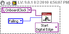
How to generate a digital signal on a negative slope of the clock?
Hello
I need to get out a finished length of the Digital pulse which will begin on request to the negative of the clock slope import (or export).
I try to get the clock, exported or imported, but in any case, I can trigger output signal on the negative slope.
What is the trick?
Thank you
Pawel
What camera you use to build your digital signal. What is the source of the clock? You can attach your vi? Normally, there is a function of data acquisition for configure the trigger where you choose the source of the trigger and the trigger slope (rising or falling), should be declining to a negative slope.
-
Anyone know if the PXI-5441 module can be ordered with the LVDS output option?
In the data sheet is indicated, that a similar, more simple PXI-5421 can generate low-voltage-diff-signal, too (not only the complete analog single).
Hello
All NI PXI-5441 modules come with the connector of the SDC, and for later reference, all options of memory except the 8MB for the NI PXI-5422/21 option will come with the SDC as well. A PIN for the CSD can be found here http://zone.ni.com/reference/en-XX/help/370524M-01/siggenhelp/5441_ni_5421_digital_connector/
-
Generation of pulses using NOR-PXI-5421 FGen
Hello Sir/Madam,
Question:
We use the Funktiongenerator NOR-PXI-5421 and just want to generate a pulse, because it can be done in almost all cheap Funktiongenerator.
Unfortunately, I can't find a way to tell the Funktiongenerator to generate a pulse. I can generate Singals as I like, but don't know how to generate a single pulse.
Perhaps you have a program that gives me this opportunity.
Thank you for your support.
Hi Jens,
You can try to use the Council 5421 scripts. The following examples of LabVIEW: "Fgen Arb Script.vi" or 'Fgen switch between Waveforms.vi' use of script to generate signals, you can create a script that generates a single DC pulse of high level in the same way.
I hope this information helps you.
Best regards
Blase
-
How to use the two counters to PXI-6280, to read and write at the same time?
Hi all
I try to use PXI-6280 counter to generate a command of step motor pulse train. The idea is to send a number done and known pulse for the engine, which belongs to a system XYZ. The point is, if, at some point, the user or the security system can interrupt the movement. If this happens (and will be... a lot), I will lose the real position, because I don't know how many pulses were actually sent to the engine. That is why I want to use the other cost to count impulses how were actually sent to the engine. I can start any tasks (generating or account), but only the first started task will operate. I met a couple of mistakes and I'm not able to find a solution.
Is it really possible to use the two counters? I've already done this in a pci system and worked without problems.
Thanks in advance,
Giavonna
Electrical engineer
I'm afraid that I don't understand your idea. Could explain you better?
Material of the series M support pointing to an arbitrary digital signals at rates (the clock must be provided from another source, for example a counter). If you want a digital pulse train finished output and have access to a counter (the two counters if find you another source for your clock, for example the subsystem "output frequency"), you must use this subsystem 'digital output' rather than the output of the counter. There should be examples in the finder of the example shows how to configure a finished task of digital output.
Now I'm generating sample clock having a single Timed material Point (the only mode accepts this mode), and configure the counter with finite samples.
I don't think not just single point NI the hardware, that's what you want. More commonly, output meter tasks use timing 'Implied', where the release date is implicitly determined by the characteristics of the pulse user-defined.
Is there a way to stop the production of only one meter when a finite number of pulses has been played in another counter?
Yes, but it's a little tricky. You can set a trigger 'Pause' on the output task, with the soruce the break being the internal release of the counter used for the task of entry. Set the initial value of the counter of entry to 2 ^ 32-N (or maybe 2 ^ 32-1-N, I don't have a system right now to check) where N is the desired number of pulse output. Together the counter event behavior for the counter edges of County switch output (this is a property of DAQmx export Signal). When the counter of entry reaches terminal, its in-house production switches, causing thus the task of output to pause. You can then stop the task in the software (you should be able to use the output of the task of entry counter event to signal to the software when the output is paused).
Now that I've written that the whole paragraph, I remember something * similar * to work around a limitation of the driver here . It is not quite the same implementation I described above, but really, you can use a meter output or a counter entry to get the same effect (it could be a good place to start anyway if you want to try this).
Is there a way to read pulses them how have been generated, without the other counter, counting impulses?
N °
Best regards
-
PXI-4461 generate voltage update
Hello
When you try to run the sample Daqmx VI "Gen - Update.vi of tension" with an NI PXI-4461, I get the following error:
200758 error:
"Type of sample Timing is set to on demand that is not supported for analog output on this unit"
What does that mean?
Is there another way to generate a constant DC signal with the 4461?
Also - for next time that consider us to buy a new card - where can I get information on DAQmx properties (like this one) are supported for each camera?
Thank you
Ran
Hi Ran,
The 4461 NOR supports HAVE no single-point / AO of because it is based on delta-sigma converters a/n/CED, which require a clock free run at a constant speed.
There are two ways to output a signal DC with an NI 4461 (or NI 4431):
- Continuously to generate a waveform to DC (containing several repeated values).
- Set channels DAQmx > AO. IdleOutputBehavior to "Maintain the existing value" can generate several updates.
The help of LabVIEW has a page of "properties of the NI PXI-4461 supported", but it does list all the supported values for each property for each device. NOR-DAQmx help has a page entitled "Considerations for DSA timing devices" that talks on this subject:
"
Considerations of timetable for DSA devices
Supported sampling frequencies
Unlike some other devices DAQmx, DSA devices have a maximum and a minimum sampling frequency. Check your device specifications determine the range of sampling frequency.
Other considerations of DSA calendar
DSA devices do not support the type of synchronization on demand. All acquisitions of DSA and generations require hardware timing of a stable clock.
DSA devices do not support external synchronization sources of arbitrary external signals such as tachometers and encoders. PFI lines on the DSA hardware can accept external clocks. You can program a DSA device to use an external clock only when it is a slave in several synchronized system device. Refer to synchronization of the DSA for more details.
"
Brad
-
I need to transfer a voltage using a PXI-5421 signal before a Council of PXI-2576 and then transfer it to an another Committee of the PXI-2576. For example I had set the signal of the ARB has then put 16 CH MUX 1(1st Switch), the value CH MUX 3 0 (switch 2) then read the MUX 3 voltage using a PXI-4071. I know that I can use the example of DMM Switch Handshaking.vi niSwitch for the rear. I'm just not sure how to transfer data to MUX 1, MUX 3?
Thank you
Denise Barajas
Hi Denise,
You must connect two switching modules to the outside. Signals may not actually be transferred through the PXI chassis backplane. Bottom of basket can only be used for communication by PCI bus and for the delivery of the trigger. You need to use external threads to physically send the signal of the first PXI-2576 to the second.
There are two ways to connect signals to the PXI-2576, you can use a block of endings that mounts to the front of the module PXI, or you can use a cable with a block of external connection. You can then connect the signal cables to the connectors to screws on the terminal/connector block. More information about the options of connection to the NI PXI-2576 connectivity products Page.
Hope this helps!
Chris G
-
is there a vi for inputs/outputs using AWG (PXI-5421) and DIG (PXI-5122)?
Hi, I'm looking for a vi that applies to an input through the AWG (PXI-5421) signal and measures the output through the SEARCH (PXI-5122). In particular, I'm trying to apply an entry by a multiplexer, then close this channel of the multiplexer through which the entry came and then measure the output using the SEARCH signal.
Any help will be greatly appreciated.
Thank you.
Hello Deepjunior,
I understand that you wanted to find an application that will be output on an AWG device and acquire a table digitizer at the same time. While there are many methods to achieve this, the easiest starting point would be to just take a simple example of niFgen and a simple example of niScope and run them together or combine them. According to exactly what your application requires, you may need to implement additional features, but it is a good starting point.
In particular, you can find an example of this from the example of area developer program: OR-TCLK synchronize AWG and digitizer high speed. Basically, this example combines niFgen and niScope examples and using the API OR-TCLK to synchronize devices. I recommend watching the program and trying to start from there. Hope this helps,
-
How can I generate modulated amplitude signal?
How can I generate modulated amplitude signal?
I got this VI examples NOR but in this VI "m message signal .vi is missing. So, how can I generate missing VI or VI full for the Amplitude modulation signal using 5441 PXI and PXI-5610 as upconvertor. If possible guide me steps to generate.
Thank you and best regards
Isabelle Kodgirwar
Graduate student
University of Texas at Arlington.
Hi Aron,
Maybe you are looking for
-
Internet service provider didn't affect my hotmail account?
I need to cancell Mts as a provider and then use Shaw as a provider. What happens to my e-mail account of windows live to mts?
-
Last thing before failure was an automatic update (15 edits total) and installation with reset. Viewed services.msc and stop and then restart all dependent services 3 listed in the error screen. No luck
-
Original title: windows Vista SP2 is not start properly. Very, very slow and do not have access to open anything. I was able to boot into safe mode and view the event viewer, and that's what he said: ./root/CIMV2 SELECT * FROM __InstanceModificat
-
Limit Internet threshold for users
Hello Is there a way I can limit user bandwidth with SonicWall NSA 6600? I saw my users are absuing very excessive Internet and thinking to apply a limit daily usage per user and per group of users to control their use. I know sonicWall is able to li
-
Mac OS x print duplex LaserJet Pro 200 M276nw
I recently bought the HP LaserJet Pro 200 M276nw understand that I would be able to do manual duplex printing. However, after reviewing the instructions in the manual and try to understand through various blogs I can't always manually duplex. The ins