PXI-5441 vs PXI-5421
Anyone know if the PXI-5441 module can be ordered with the LVDS output option?
In the data sheet is indicated, that a similar, more simple PXI-5421 can generate low-voltage-diff-signal, too (not only the complete analog single).
Hello
All NI PXI-5441 modules come with the connector of the SDC, and for later reference, all options of memory except the 8MB for the NI PXI-5422/21 option will come with the SDC as well. A PIN for the CSD can be found here http://zone.ni.com/reference/en-XX/help/370524M-01/siggenhelp/5441_ni_5421_digital_connector/
Tags: NI Products
Similar Questions
-
The streaming of data in c (PXI-5421)
Hello
I do the data streaming in C by PXI-5421 follow this instruction: http://zone.ni.com/reference/en-XX/help/370524R-01/siggenhelp/streaming/
Here's my psudo code:
1 set the amount of memory shipped to use for streaming
waveformSize = 1048576;
short * CurData [16];
checkErr (niFgen_init (resource, VI_TRUE, VI_TRUE, & vi))
checkErr (niFgen_ConfigureChannels (vi, ChannelName)); ChannelName = '0'
checkErr (niFgen_ConfigureOutputMode (vi, NIFGEN_VAL_OUTPUT_ARB)); //Arbitrary mode is used
checkErr (niFgen_ConfigureSampleRate (vi, SampleRate)); Rate of sampling = 40e6;
checkErr (niFgen_AllocateWaveform (vi, ChannelName, waveformSize, & wfmHandle)); Allocate memory for broadcast borad
2. identify the waveform streaming
checkErr (niFgen_SetAttributeViInt32 (ChannelName, NIFGEN_ATTR_STREAMING_WAVEFORM_HANDLE, vi, wfmHandle));
checkErr (niFgen_SetAttributeViReal64 (vi, VI_NULL, NIFGEN_ATTR_STREAMING_WRITE_TIMEOUT, 10.0)); Set TimeOut = 10 s
3. fill the waveform continuous initial data
for (j = 0; j<>
fread (CurData [j], sizeof (short), waveformSize/16, PlayedFile); Read data from my saved file
checkErr (niFgen_WriteBinary16Waveform (vi, ChannelName, wfmHandle, waveformSize/16, CurData [j]));
}4 start generating the waveform
checkErr (niFgen_ConfigureOutputEnabled (vi, ChannelName, VI_TRUE));
checkErr (niFgen_InitiateGeneration (vi));5 write a waveform data block. (Optional) Monitor available memory that generates the waveform
{}
niFgen_GetAttributeViInt32 (vi, '0', NIFGEN_ATTR_STREAMING_SPACE_AVAILABLE_IN_WAVEFORM, & FreeSpace).{if(FreeSpace>=waveformSize/16)}
fread (renewData, sizeof (short), waveformSize/16, PlayedFile);checkErr (niFgen_WriteBinary16Waveform (vi, '0', wfmHandle, waveformSize/4, PlayData));
//}
} while (1);I properly generate first 1048576 points of data. However, I'm stuck in writing new data in my space of memory onboard.
The error message space in continuous waveform has not become available within the specific period, and appears after 10 sec which is my time-out period.
If I check my available space via the property NIFGEN_ATTR_STREAMING_SPACE_AVAILABLE_IN_WAVEFORM, it never increases. Did I miss something? Can I work in arbitrary mode for data streaming?
Any suggestion is appreciated. Thank you!
Looking at the example LabVIEW/CVI, it seems that you are on the right track.
If you remove the Do / While loop, do you still 1114112 samples? In other words, samples of 1048576 (1048576/16)?
What is the value returned by ' niFgen_GetAttributeViInt32 (vi, '0', NIFGEN_ATTR_STREAMING_SPACE_AVAILABLE_IN_WAVEFORM, & FreeSpace)? "
I have attached the CVI example in this post. It has many additional functions that change the GUI of the CVI, but ANY function calls should be the same. Is the only thing that is considerably different that they set a number of rehearsals and use unique relaxation mode. I would go ahead and change your code to be similar in order to ensure that it is no hardware problems. Then I would try to generate and disseminate a sinusoid first before trying to use your file. I hope that we can refine all the problems.
Jason L.
-
PXI-5421 Signal routing to PFI4 and PFI5
Hello
I am trying to route bits 0 and 1 of a waveform I generated using a PXI-5421 AWG group work PFI5 and PFI4 respectively for the ports. What seems to happen, this is the first installation is written the second set so that only one PFI port is set up. I've attached a screenshot of a section of the configuration of the VI. Can two bits of a waveform being routed to two ports separated the IFP at the same time?
Thank you
Steve
Hi Steve,.
Yes. There is data on the PXI-5421 4 markers, and each can be configured with unique values for each of the attributes of data marker. To set up the markers of data independently, you must specify a 'Active Channel' for the polarity of marker data and number of bits attributes. So in your example, you would just need to add an entry "Active Channel" on your property node above the attributes of marker of both data and wiring in the "datamarker0" to set up the first brand of data and the "datamarker1" for the second. "NiFgen waveform Arb marker" shows how to do this. Do not wire the active channel range cause really all markers 4 data to configure when the value of each attribute of data marker.
Hope that helps.
-
Generation of pulses using NOR-PXI-5421 FGen
Hello Sir/Madam,
Question:
We use the Funktiongenerator NOR-PXI-5421 and just want to generate a pulse, because it can be done in almost all cheap Funktiongenerator.
Unfortunately, I can't find a way to tell the Funktiongenerator to generate a pulse. I can generate Singals as I like, but don't know how to generate a single pulse.
Perhaps you have a program that gives me this opportunity.
Thank you for your support.
Hi Jens,
You can try to use the Council 5421 scripts. The following examples of LabVIEW: "Fgen Arb Script.vi" or 'Fgen switch between Waveforms.vi' use of script to generate signals, you can create a script that generates a single DC pulse of high level in the same way.
I hope this information helps you.
Best regards
Blase
-
PXI-5421 generating an arbitrary signals on the fly
I have a card PXI-5421. I need to generate an arbitrary waveform with different frequencies. I need to have a trigger to switch between Forms of waves of different frequencies. I use the script to do this. I'm not able to update the frequency of the next wave on the fly without stopping the program. In other words, can I download signals in real time? The code is attached.
Hey Kakrott,
You should be able to achieve this with your PXI-5421. The example of 'switch between the waveforms FGEN"in the examples of LabVIEW makes something similar to what you're trying to do. As explained in the documentation: "this example shows how to switch between two different wave forms while generating, using updated data every time." This example uses a trigger to change what waveform is generated.
-
is there a vi for inputs/outputs using AWG (PXI-5421) and DIG (PXI-5122)?
Hi, I'm looking for a vi that applies to an input through the AWG (PXI-5421) signal and measures the output through the SEARCH (PXI-5122). In particular, I'm trying to apply an entry by a multiplexer, then close this channel of the multiplexer through which the entry came and then measure the output using the SEARCH signal.
Any help will be greatly appreciated.
Thank you.
Hello Deepjunior,
I understand that you wanted to find an application that will be output on an AWG device and acquire a table digitizer at the same time. While there are many methods to achieve this, the easiest starting point would be to just take a simple example of niFgen and a simple example of niScope and run them together or combine them. According to exactly what your application requires, you may need to implement additional features, but it is a good starting point.
In particular, you can find an example of this from the example of area developer program: OR-TCLK synchronize AWG and digitizer high speed. Basically, this example combines niFgen and niScope examples and using the API OR-TCLK to synchronize devices. I recommend watching the program and trying to start from there. Hope this helps,
-
Pxi different 2-5421 or-tclk synchronization help and reversing a signal
I have 2 PXI-5421 function generators. Screened through my vi I load a .hws file and output the same signal makers 2 all in phase and triggering the same point. I need basically to do, it is reverse one signal of 180 degrees and keep them always trigger the same starting point.
im not sure how is invert the signal on a 5421 or how to separate code so that each signal generator is separated.
Hi Liam,
I did a quick search on your issue and I think it is interesting to try to 'configure exit Mode.vi niFgen' (red border on the screenshot) and the value
output mode of entry to the "arbitrary signals" (right click on the parameter "Output Mode"-> create constant-> select 'arbitrary signals' in the drop-down list).
You could include a code of the error you found in your next reply. Thank you!
All the best,
-
Error-201427 on PXI-5122 since NI MAX system
I need to check that the PXI-5122 is supported by NO-Scope 4.0.0 under WINdows 7 64-bit. If so, I guess I can get a damaged card. The system was running under the old computer / code / drivers last month.
Scenario is this: I'm upgrading of already running code to a new computer and 32-bit 64-bit CVI CVI. After plowing, of code tweaks, PXI, 5122 digitizer shows through a new error in the code. I go back NI Max and I get this related error when I try to post.
"The driver could not communicate with PXISlot2, generates the following message:
Error-201427 to the autotest
Possible reasons:
The specified device is not supported in the API OR-DAQmx.
Specified device PXISlot2.
Seeing this, I have tried NOR updated, and nothing has been marked. I shut down the system and reseat the card. Then I checked the version of NOR-Scope (was 3.9.4) OR MAX I downloaded manually OR-Scope 4.0.0. Same mistake.
The 5122 is in slot 2 and NI MAX identifies the card as "2: NOR-PXI-5122"PXISlot2"
More information on the current system
Dell Precision T3600
Win7 64 bit Enterprise SP1
Spincore NMR TIming Pulsebalster PCI card
PCIe copper x 4 remote link to the chassis OR 1062 q
In the NI 1062 q
Slot 1: NI SMU-8370 remote control
Slot 2: OR PXI-5122
SLOT3: NOR SMU-5442
Slot 4: reports of empty in fact NEITHER SMU-8262 linked to a NI PCIe-8263 (shows in Windows, normal visibility NI Max is unknown)
Slot 5: OR PXI-6733
Slot 6: OR PXI-6733
Slot 7: vacuum
Slot8: OR PXI-5421
Measurement and Automation Explorer System Information (current after upgrade NI-Scope) is attached
Before I track down a loan 5122, I wanted to see if there are known incompatibilities that come to mind.
Thanks in advance.
There is a material-200313 error on the map (and the first replacement) as revealed by an earlier version of NIMAX (another computer and PXI chassis). The information contained in the attached document can help improve diagnosis in the future (rather than the more highest credits of the error).
With a third scanner system is running.
-
replacing existing ATE traditional PXI based ATE
Hi all
We use a traditional ATE equipped with traditional instruments for example transmissions
 cope, Agilent: switches; Mux; Matrix; DMM; Generating function, Chroma
 ower supply, etc...
I contacted OR to obtain praposal to replace these instruments OR instruments. The price of the products OR is higher than the traditional instruments of compratively. Now it's hard for me to propose this to my managemnt.
Which in general; You people do to replace the traditional ATE with this new S/o, PXI?
Can I use same digitizer for high channel count to replace measuremnt instrument such as scope, DMM?
- DMM: PXI-4072 (I LOVE this DMM)
- Switches/MUX: NOR has a good range of PXI switches that work well. I wanted to play with of Pickering PXI switches, especially their BRIC.
- Function generator: the PXI-5421 is a very good generator of arbitrary signals.
- Power supplies: Agilent has a good series of modular power supplies (N6700 series). You can put up to 4 power supply is a single 1U chassis and communicate with them via LAN.
- I use Chroma electronic loads, but I don't really like them for situations that I was forced to use them. They are really good for loads of constant currents, but I hate them for the constant resistance loads, unless you are less than 100 Ohms. Always looking for alternatives. Also glued using GPIB or serial communication. I'm trying to push to the local network for cost reasons.
- Oscilloscope: I found that the transmissions expanded are the best way to go. It is really hard to replace a real screen on a scope that you can play with during troubleshooting. And the means of integrated measures, I don't have to deal with the wave form myself. Yet once, talk to her on local network.
- Counter source (power supply with a multimeter accurate built in): been using the Keithley 2425. Tempted to look at the NOR meters source especially because Keithley seems just refuse to go to the local network. But it's a counter very good source.
In my honest opinion, PXI has its place and have their own traditional instruments. PXI is very good for the right instruments (switches, multiplexers, DMM, AWG, low current power supplies to). But I find the traditional instruments are necessary for feeds that need to come out of the current charges and decent electronic (again, due to current needs). I used scanning cards of EITHER before, but I always come back when I have to debug and how it is nice to have a real screen showing my waveforms and then be able to play with the sliders on the fly.
-
I need to transfer a voltage using a PXI-5421 signal before a Council of PXI-2576 and then transfer it to an another Committee of the PXI-2576. For example I had set the signal of the ARB has then put 16 CH MUX 1(1st Switch), the value CH MUX 3 0 (switch 2) then read the MUX 3 voltage using a PXI-4071. I know that I can use the example of DMM Switch Handshaking.vi niSwitch for the rear. I'm just not sure how to transfer data to MUX 1, MUX 3?
Thank you
Denise Barajas
Hi Denise,
You must connect two switching modules to the outside. Signals may not actually be transferred through the PXI chassis backplane. Bottom of basket can only be used for communication by PCI bus and for the delivery of the trigger. You need to use external threads to physically send the signal of the first PXI-2576 to the second.
There are two ways to connect signals to the PXI-2576, you can use a block of endings that mounts to the front of the module PXI, or you can use a cable with a block of external connection. You can then connect the signal cables to the connectors to screws on the terminal/connector block. More information about the options of connection to the NI PXI-2576 connectivity products Page.
Hope this helps!
Chris G
-
Hi, I have NI PXI-5600 on chasis 1045 PXI and PXI-5620, PXI-5610, PXI-5421, PXI-4461(from left to right in the pic)... Apparently, I have installed all the drivers correctly and the wiring... Screenshots of my connections and MAX windows are attached. I don't understand where is the problem.
I have reset the device, but it does not work. think I understood the problem. It seems that the problem is not in PXI-5600. The problem is with the PXI-5620 because
Or Pxi-1) 5600 showing "working properly" in the VISA properties. Photo #1
(2) PXI-5620 self test not available due to his inconsistency. Photo #2
(3) in goods NI PXI-5600, it cannot be linked to 5620. Photo #3
Now a similar solution is given here http://digital.ni.com/public.nsf/allkb/ABBB55946EB39A02862571FD0052024C
My question now is that I HAVE IDENTIFIED THE PROBLEM CORRECTLY do I ignore the 'self test failure of the PXI-5600' and try to link that the way in which it is mentioned in the solution in the link above and my VNA PXI-5660 in labview will work well with it... Or y at - there a way to fix this incompatibility of the PXI-5620 with DAQ - mx...
Thanks for your time...
-
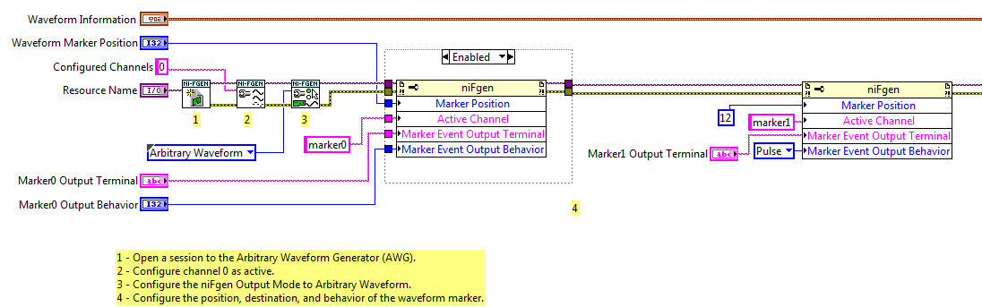
Export of multiple markers in mode of arbitrary waveforms
I use the example Fgen Arb Marker.vi waveform (in the examples of LV2011) as the basis for the production of markers and exporting to PFI0 and PFI1 on a PXI-5422.
I added a 2nd call of property node after the first configuration of marker1. The program runs without error, but only generates marker0. It seems that if I configure Active Channel as 'marker1' or 'marker2' or 'marker3' or 'marker4', the property node has no effect. I expect that subsequent calls must set up additional markers.
I used the script mode to configure several markers with my generator signal as well, but I'm trying to understand how things work in mode of arbitrary signals for some legacy code.
So just to summarize, things that I confused me more than before and during this thread have been:
1. lack of feedback of error/warning when configuring marker1-marker3 in wave arb mode
2. the general statement "a marker by segment" seems inaccurate given the script arb mode
3. script view arb is not mentioned in the PXI-5422 or PXI-5421 hardware specification
1. the Council supports 4 markers, numbered 0 - 3. So when you configure those, you do not get an error. When you configure marker4 you get an error because it does not exist.
2. I think you are right, that the statement applies to arbitrary waveform Mode, no Mode Script.
3. it's probably another problem of documentation. Script mode was not supported when 5421/5422 first came out, so my guess is that when a support because it has been added, the documentation was not updated.
Good luck
Marcos (not Marco
 )
) -
Correct calculation of delay of release in niScope_ConfigureTriggerDigital
In the case where we use the delay trigger option form niScope_ConfigureTriggerDigital, the entry is a real double precision in units of seconds. This value is probably converted to periods of integer sampling dwell "behind the curtain of sorcerers." Would this conversion be better approached by a ceiling, the floor and the round function. This conversion is compatible for all versions OR Scope (and I hope future versions.)
Finally, the accuracy of the measurement of this value on a locked Tclocked PXI 5421/PXI-5122 is based on the accuracy of clock of the digitizer, the accuracy of clock PXI and precision of clock AWG. Given that the precision of the relaxation is essentially the Tclock, only the digitizer clock accuracy (since it's free during the pre-trigger scans) and the number of pre-trigger scans really add to this Tclock error?
FYI - the value is needed for gives the first phase (and in our case there is unfortunately zero displacement of first and second order phase) of a signal of our ICR mass spectrometer.
Thanks, Greg
Greg,
To lock the two planks together using TClk will configure them to start triggers and ensure that they both start together. When they are Tclked together they will recognize the triggers on the edge of the TClk. The TClks on the two cards will have a small amount of obliquity that is constant for a system and can be measured. Measurements with the system can then be adjusted to take account of the tilt. Only jitter in TClk comes from the individual advice clock jitter. If you configure the digitizer for a trigger reference the tripping time will be as accurate as it would be in a normal case, and it is possible to understand when the reference trigger occurred compared to 5421 time.The triggering delay will be get rounded.
Stephen
-
Trying to shutter AWG out digitizer (CVI)
I work with an arbitrary wave generator NI PXI-5421 and digitizer PXI-5211.
With CVI, I let a waveform with the AWG output 500ms after the scanner is triggered.
Is this possible?
To set up triggers, I used the following two functions:
- niFgen_ConfigureDigitalEdgeStartTrigger (AWGHandle, "PXI_Trig1", NIFGEN_VAL_RISING_EDGE);
- niScope_ConfigureTriggerOutput (ScopeHandle, NISCOPE_VAL_START_TRIGGER_EVENT, NISCOPE_VAL_RTSI_1);
However, I was not managed by entering the ARB to produce anything once the scope is triggered.
I'm missing steps crucial or is - something that cannot be done in the way wherein I try?
Thanks for your help.
Hello
I think I see the problem. It seems, it's that you configure your digitizer and fgen correctly if they were going to be run separately, except for one thing. In this section:
Digitizer of config.
....
Set up the output trig for digitizer to trigger AWG
error | = niScope_ExportSignal (ScopeHandle, NISCOPE_VAL_START_TRIGGER, "", NISCOPE_VAL_RTSI_0);you export the start trigger, which is in fact sent immediately after you call the niScope_InitiateAcquisition() function. All this is done before you set up your AWG, so start trigger is already sent before calling the niScope_InitiateGeneration() to the working group. Also, I suppose that you want to trigger off the trigger of reference that you configure your call to the niScope_ConfigureTriggerEdge() function. I have attached a picture of the help file for this function.
There are two things you need to do to solve this problem.
1. you need to change this line: / / output trig to trigger AWG scanner configuration
error | = niScope_ExportSignal (ScopeHandle, NISCOPE_VAL_START_TRIGGER, "", NISCOPE_VAL_RTSI_0);to export the reference trigger instead: / / output trig to trigger AWG scanner configuration
error | = niScope_ExportSignal (ScopeHandle, NISCOPE_VAL_REF_TRIGGER, "", NISCOPE_VAL_RTSI_0);2. in addition, you must move the niScope_InitiateAcquisition() function to be called after the function niFgen_InitiateGeneration():
"....
Activate the AWG output
error | = niFgen_ConfigureOutputEnabled (AWGHandle, '0', VI_TRUE);Output of arm
error | = niFgen_InitiateGeneration (AWGHandle);Acquisition of digitizer Begin
error | = niScope_InitiateAcquisition (ScopeHandle); "According to me, who must take care of it.
Chris W
-
Hello
We thought to use a map of PXI-5421 arbitrary signal generator to generate a signal of 'light at the top' 50 Hz, but the maximum amplitude of the signal must be +/-14V but available from the 5421 maximum amplitude is +/-6V, ideas?
Concerning
Steve
Yes. You will get (27 000 / (27 000 + 50)) = 99.815% of the tension in your load, or +/-11.978 V.
Neil

Maybe you are looking for
-
Just posted a question, I want to remove
-
Windows Vista Home, profile connection failure
After the opening of Windows, where try to connect me to my profile, I get this message "the service user profile Service has no connection. User profile cannot be loaded. "I'm the only Admin, so even if I try to set up a new account I can not.
-
I own a dell server t630 no pcie hardware flash. How to have two nvme SDS samsung xs1715 that the dell hardware must provide how would these two ssd drives can be used in dell t630? Or material not dell. THX Alex
-
Hi, I did some research on Google and scanned through the rim of the api documentation and cannot find a reference to the voice at all, I missed something? I would like to be able to implement speech-to-text in my application, I will then send the te
-
Channels disappear in WMC at the output via HDMI
I have a tuner TV USB (connected to an internal antenna) on my Windows 7 laptop. When I use just the laptop, I can watch TV without any problems. However, when I connect the laptop to a monitor via a HDMI cable, all channels disappear and running a s