Arbitrary signal generation
Hello
I would create a program that simulates the signal given by the contraction of a heart Chamber. It should be periodic with an adjustable frequency and amplitude. I use a structure of the event with a time-out interval equal to the time interval of the signal and a block "simulate arbitrary signals." The problem arises when the signal trace because the graph shows all forms of wave side by side instead of not not been zero only after than all of the time interval. You will find attached an example of signal I would get and that I receive and the labview VI.
I hope my question is clear, thank you in advance for the help.
Federico
So, you want something like that?

Tags: NI Software
Similar Questions
-
generators of PXI arbitrary signals compatible with the generation of ssb vi
There of SSB generation vi, what Arb. People of waveform. will work for the PXI system? 54xx?
Here is a list of our arbitrary signal generators that this vi should work with:
NEITHER 5411, 5412, 5421, 5432, 5441, 5442, 5450 and 5451
-
Unable to send arbitrary signals of CC. Help. Please, I beg you.
Hello people,
I am a student of Btech working with Labview 2013. I managed to generate an arbitrary Signal through Labview 2013 version for my project. Now, I need to send the signal to Agilent 6642 power supply dc to ampilfication and it will be used for my experience. I am facing problem here.
I use GPIB USB HS to send the signal, and when I send commands * IDN, is successfully reading and writing, which means I have all my software and drivers installed perfectly. I have installed in my pc control expert and NI MAX.
I did a program (which is attached) in labview and the GPIB seems to read (signal ACTIVE/Green shows when it is executed).
But I do not see it in the oscilloscope (Tektronix TDS 2024 B) which means something's wrong here. I need to see the signal as shown in the attached picture.I am new to labview and don't know much. Please help me with the Labview program as I want to see the signal in the oscilloscope as well.
If a command is needed, let me know the order.
I'm stuck. Help, please.
Thank you.
-
Example of arbitrary signals fgen does not
Hello
I use an example of NOR-FGEN - "any arbitrary signals." I want to activate the digital filter, but there is an error occurred. What should I do to fix this error?
bahec666,
The SMU-5451 does not support a digital filtering. That's why you get the error message that you are experiencing.
-
Hello, I'm trying this arbitrary signal by arbitrary simulation of output signals express VI. I want an exit point out analog of the DAQ USB 6281 every second. When I said to output a point by iteration I get error 200609 say the selected buffer size is too small (selected the size of the buffer: 1, minimum buffer size: 2) how can I change the buffer size? attached if my VI, just go under the 1 'arbitrary' case and you'll see my VI Express with points iv series.
But you are passing an array many points so you should have to index this table point by point by putting the DAQ Assistant, in a loop with a delay of 1 sec. You can also spend the whole wave and specify a frequency of 1 Hz in the DAQ Assistant.
-
Using simulate arbitrary signals
Is it possible to import more than 100 samples with the VI express to simulate arbitrary signals? When I try to "load data" in the signal screen set it is important only 100 lines
You are 100 samples of playing at a time and put them in a single file?
Somehow, you had 100 samples written in the file at the moment that the header has been created, but a 38 000 added another samples after that. If you change the 100 at 38100 in the header of this text file, you will see all of your points added.
-
Timed signal generation TTL with the NI USB-6501 to be read by Arduino Uno
First of all, I want to apologize - I am very, very new to LabVIEW and brand new to the development of the software of control equipment in general. I tried to find an answer to this question already, but I'm not entirely sure what I'm looking for.
I have currently a work program LabVIEW which operates a gun card NI USB-6501. Due to the nature of having a machine that springs from a powerful beam of electrons, we want to assure you that if the computer controlling stalls or fails for any reason, we have built-in security that can stop the gun. Our current idea is to connect an Arduino Uno on a PIN on the USB-6501 and LabVIEW to generate a timed signal, which may read the Arduino. If the signal fails (indicating that the control computer has queued or off), the Arduino triggers a power relay that is independent of the control computer and turns off the gun.
I understand that the USB-6501 operates on TTL signals, so the signal that I should be something in the sense of "output TTL high, wait 1 second, output low expectations, a second, repeat TTL ', but I have no idea how to go about programming in LabVIEW. My first thought was that it is a square wave by using the function "simulate the signal" output, or to have trigger an iterative Boolean signal, by using the function 'DAQmx write', but I don't really understand how do to implement or another idea, or if an idea would even work.
Any advice would be greatly appreciated.
Hi Elizabeth,.
THINK THE STREAM!
When do you DATAFLOW think everything falls in places!

Several problems:
-You have to put that MAKE impulse VI in his own loop parallel to your main VI!
-When you place this generation of impulses in the effects loop ("TTL arduino low-high") you should put the CreateTask and StopTask outside the loop: no need to create/stop the task in each iteration.
-Why are there points of constraint to waiting functions?
-Why is there bent wires? You know Ctrl-U?
-LabVIEW comes with an extensive library of example screws: you looked at all these examples DAQmx?
-Suggestion: Learn more about the "structures of producer-consumer"!
-
PXI-5421 generating an arbitrary signals on the fly
I have a card PXI-5421. I need to generate an arbitrary waveform with different frequencies. I need to have a trigger to switch between Forms of waves of different frequencies. I use the script to do this. I'm not able to update the frequency of the next wave on the fly without stopping the program. In other words, can I download signals in real time? The code is attached.
Hey Kakrott,
You should be able to achieve this with your PXI-5421. The example of 'switch between the waveforms FGEN"in the examples of LabVIEW makes something similar to what you're trying to do. As explained in the documentation: "this example shows how to switch between two different wave forms while generating, using updated data every time." This example uses a trigger to change what waveform is generated.
-
Hi guys,.
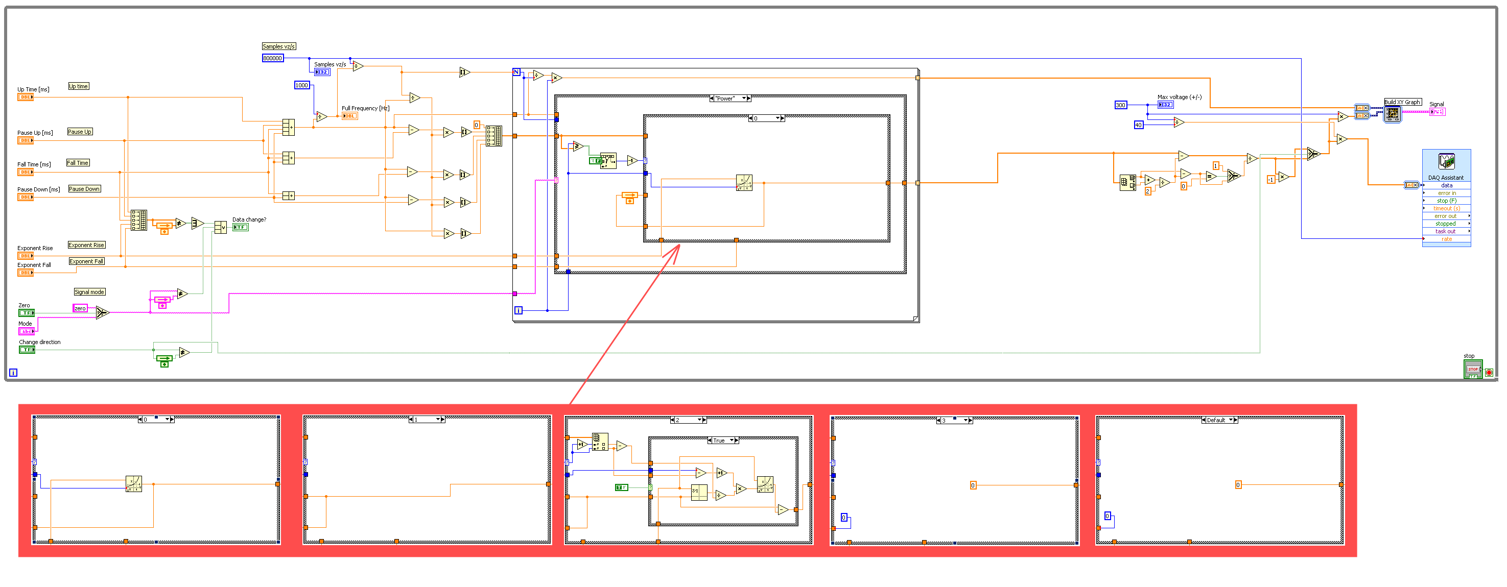
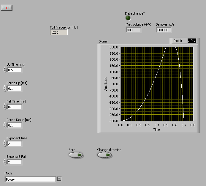
I have big problem with my signal generator and have no idea where can be a problem. I did a LabView program to make the signal that I am the phone my NI PCI-6221 card thanks to the DAQ Assistant. My program is:
The Panel fromt with indicated generated signal is:
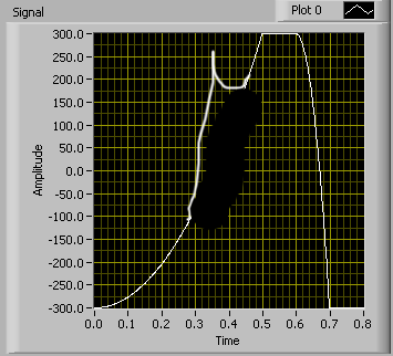
But my problem is with the evolution of my signal parameters in the build process. For example when I change the weather, so the square exhibitor will take more time, I see on my osciloscope some rest of the previous signal. So the final singal (osciloscope) looks like this:
(Sorry for the hand-painted painting)
If I stop the program and start it again the new signal with new parametrs is built perfectly. So I think that the PCI 6221 once I have changed some settings is not throw all the data in the buffer (at least I think). For the DAQ Assistant, I use continuous sample with 800 k samples per second. With this mode (continuous sample) I get this remain on new signal signal. When I tried to use N samples mode, it seems to work fine, but generation time is really slow, medium, once per second and I need to use my card for data rading too so it's out of the question. I tried to program this PCI card manually write function (instad of DAQ Assistant) too, but then I ger hard signal which is really not so smooth from DAQ Assistant. I evn tried to change the number of samples each time when I change some parameters, but it did not work. I'm sure I'm doing something wrong, but after two days of looking for a solution, I'm out of ideas. So question is where can be the problem and how to change signal parametrs without obtaining this rest of signals, means how to clear buffer completely when I changed the signal. I use LabViw 8.5 but it is possible to use any newer version too, if you think that old version of labview can be the problem.
OK I found the solution, it was impossible to use the normal function of Express DAQmx. After that I changed slightly this explicit function block, everything was fine. It was necessary to recalibrate the output of my card every time when I changed one of my settings. So whenever I changed something, I stopped my bit of any communication outupts and reinicializate of my PCI card.
-
I am trying to generate a RS-422 PPS signal using the PXI OR PXI-8431/8, LabWindows/CVI and CVI standard library functions, but I can't find a way to produce a signal that remains HI with persistence for X number of ms. I realize that use the PXI-6602 would be an ideal solution, but in my case, I am relying on the RT OS to maintain determinism. Do you know a white paper or a thread that could describe a reliable way to do this with the functions of the ICB boards of series I have?
This message has been copied since the LabView discussion Forum. Sorry for the inconvenience.
Sean,
I've updated the functions of generation of pulse with those of the DAQmx library and am now running.
Thank you a lot for the input.
J
-
USB-6501 open collector signal generation
Hi all
I have carefully read the manual for this product, and I think that's what I'm looking for, but I was hoping just to get confirmation from someone who knows a bit more about it as I do. I have a stepper motor command that accepts control impulses. The differential voltage between the 2 input pins must be between 2.5 and 5 V DC. The control pulses can be RS422 or open collector type signals. The maximum heart rate is 250 kHz, pulse length must be greater than or equal to 2 microseconds and the time between two pulses must not be greater than 40 milliseconds. The engine must operate continuously for an extended period of time. Yet once, seeking confirmation that DIO can produce the signal I need. Thanks for any help.
It seems to me that this module can be adapted to be connected to your driver module. Output configuration you need is called "open-drain output" in the data sheet.
It is possible to drive a stepper motor driver with a generalist module e/s. But (in most cases), it is NOT possible to drive of a driver of motor Stepper with a constant pulse. You will need a rate of acceleration, i.e. it must increase the frequency of the pulses of zero to the desired speed of the engine.
-
Good evening
I am trying to generate an output voltage and I am facing some problems. I am using an analog input voltage NI 9263 module, I have two sons (AO0 and COM) connected to the terminals positive and negative a BNC connector; I want to generate an alternating voltage, 60 Hz and amplitude of 1 to 5 V. Unfortunately what I measured with a multimeter is something always scaling, for example: if I generate a signal of amplitude 1 I measure 0.7 volt, if the signal is amplitude 2 to I measure 1.4 and so on. I would like to know if some of calibration is required or there are potential errors in what I do.
Thank you.
Sorry, but am not at all in agreement with this response.
A BNC connector has no impedance any of its own. The output impedance of a signal generator is determined by the circuit, not by the type of connector.
Anyway, even if the output of the circuit impedance is 50 ohms, it is not the reason for your reading. The mulitmeters input impedance is high enough does not create a voltage with an output drop rather low impedance. The reason is probably the difference between a peak to peak of current voltage alternating (AC) and the RMS value. In your case, probably the software defines a range of crete and an RMS value is measured by the meter. The effective value is always the peak divided by (root of 2) value.
See also
http://86.43.94.97/moodlecp9a/mod/glossary/showentry.php?CourseID=1&concept=RMS+voltage
-
Analog output of signal generation custom
Hello
I have a VI that generates a signal from the values in an excel worksheet. I'm trying this waveform through an acquisition of output data. I use a box NI USB-6211.
I copied the exit code for the acquisition of data from other VI that generates a sinusoidal signal coming from an excel worksheet. This program works very well. (attached for reference - Analog Output VI + sinusoidal waveform)
I have two problems at the moment. First of all, I get error-200560 about waiting until the function, attached.
Second output amounts only to about 5.5 v instead of 9V specified in the data.
My VI generate several types of waveform according to selected tests, but I'm trying to get an output DAQ working with the first test, named "disconnection of the battery" work first before implementing it in the other tests so please ignore others for now. To run this battery select VI disconnect under tests select then direct to the attached excel (BD values under 10V) file.
I hope that I myself have pretty much explained, otherwise please ask for more! I'm new to LabVIEW so your help would be very appreciated.
Thank you very much
Parker
aeParker wrote:
I've made a few improvements to the VI but I always feel the DAQ 5 Cap output, 5V.
Dear Parker,
I guess that this statement is based on the values in the chart show, AO 0. However, this is not (necessarily) the voltage produced by AO 0, but rather the tension being sampled by AI0. If you look at the DAQmx create channel for the AI voltage channel, you will see that you have left entries Maximum and Minimum Value unwired, which means that they take their values default to + 5v and - 5v. This may explain the behavior of cutting that you observe. Try the + 10 and -10 wiring and see if that solves this problem.
Bob Schor
-
Hello world
I use the Modulation Toolkin do my thesis, specifically, I work with the driver NOR RFSG. The VI called "niRFSG set up generation Mode.vi" needs to set an option (the mode of generation). You can choose between a CW, arbitrary waveforms and a script. Well, I have to use the option of arbitrary signals but I do not quite understand, but that means. What type of waveform is generated? Where can I find more information about this?
Thank you.
Hi kantabra
When you use the method of arbitrary signals, you must set the IQ data yourself that is generated. I suggest you take a look at the example that accompanies the driver NI RFSG. You can find it through arbitrary waveform Generation.vi help - find examples - material IO - Modular Instruments-OR RFSG - arbitrary signal generation - RFSG
This example shows how to use this method with your signal generator.
-
Cannot find examples of generation signal
Hello
Here is the page with information about the signal generation modules
http://zone.NI.com/reference/en-XX/help/371361H-01/lvanls/signal_generation_vis/
At the bottom of the page, there is information that these examples can be found at the following location:
labview\examples\analysis
But in my version, there is no file examples\analysis.
Where can I find these examples?
Thank you
This link is LabVIEW 2011. One of the best features of 2013 was a complete redesign of all the examples! Look here
\examples\Signal Processing\Signal generation directory
Maybe you are looking for
-
compatibility issue with the software for Windows XP
When I try to install a program, it says that I need to be runniing in windows XP. I try to install the program in compatibility mode and get the same message, and the program does not load. When I called the technical support for the program they te
-
I have to show some information. If the information is more than one line, it will be automatically breaks into several lines. To do this, I created my own CustomLabelField. It works very well. But when I add several CustomLabelFields in a VerticalFi
-
Not correct labels in Gmail from blackBerry Smartphones
With the help of 6.0 on my 9700, labels for my Gmail account are mixed up - which shows the device does not match what is shown in the webmail. Any ideas? All my tags are listed, but if I assign a label on my device, it appears as something completel
-
Just check out my credit card balance and paid me for creative cloud for two months, I have no idea how it happened, I go on my account and it tells me I have the free subscription if I can't find the payment to cancel my subscription. I can not real
-
JavaFx and fxml in an OSGI runtime
Hello I work to run javafx in the Apache felix osgi runtime,using Bundle-NativeCode and many import/export-package, I do a javafx bundle, that works perfectly to run javaFx interfaces written in plain java...but, when I try to load a fxml file I get