How to generate a digital signal on a negative slope of the clock?
Hello
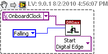
I need to get out a finished length of the Digital pulse which will begin on request to the negative of the clock slope import (or export).
I try to get the clock, exported or imported, but in any case, I can trigger output signal on the negative slope.
What is the trick?
Thank you
Pawel
What camera you use to build your digital signal. What is the source of the clock? You can attach your vi? Normally, there is a function of data acquisition for configure the trigger where you choose the source of the trigger and the trigger slope (rising or falling), should be declining to a negative slope.
Tags: NI Software
Similar Questions
-
generate a digital signal for 6722 or 6221
Hello
Thanks first for the help I'm already on this forum.
Now, I have the following problem:
I like to generate a digital signal: high for 300µs, low 300 µs, 300µs high, low 300µs, top for about 2 ms.
I'm looking for a solution how to generate this numerical sequence. At the same time, I will read the information via an analog input (if all goes well, I now have a solution for this problem).
I tried to find examples, but I failed. For the moment, I was not able to produce any numeric sequence that worked.
My hardware is 6722 or 6221 - which should be OK with respect to the calendar.
Thank you
-
How can I get digital signals (interface UART) with a microcontroller with NI USB-6008?
I have acauired a few analog signals by A/D (3 channels). I put each scanned data on 3 digital output with a microcontroller. I want to see if it is possible to import these digital outputs 3 to a PC via a USB-6008? It's like the connection of the output to the digital input of the USB-6008 and import the 3 channels simultaneously to LabView? Do I need to use some other hardware like USB-8451 and connect the clock of the MCU to USB-8451?
Saraydin,
The digital I/o on the USB-6008 is a software program only, so unless your signals are rather slow, it probably will not work for you. In general, the procedure would be to connect each signal to one of the digital lines on the map and then set up a digital entry into LabVIEW task to read the three channels. If you use a device that has clocked by the digital i/o hardware, you then your input clock signal and use it as the sample for the task clock. Here is a list of USB devices supporting DIO clocked by the hardware. Also, there is an example that comes with LabVIEW, which shows how to do this. You can get to it in LabVIEW by going to help > find examples. When the example Finder window opens, navigate to hardware input and output > DAQmx > digital measures > Cont read dig Chan-Ext Clk.vi.
The 8451 is specifically for I2C and SPI, and would be great if you try to make one of these protocols, but otherwise I would recommend the devices in the list I linked above.
-Christina
-
How analog out simultaneously a signal and its negation?
Hello
I use the 6024E and trying to send a signal with an analog output.
However, at the same time, I would like to send a negation of this the other analog output signal.
It seemed simple until I realized that this timed task alone is supported at a time.
Any suggestions would be most appreciated... I have attached the vi I thought that (but now realize will never) work.
Thank you!
You should be able to put the two channels in the same spot. Not had time to test this, but it should work.

-
How to generate a pulse signal?
Hello
I'm relatively new to LabVIEW and I need to generate an impulse (Dirac function) in the motor continuous. At the same time, I need to be able to change the pulse width.
I am currently using LabVIEW 7.1.
Hey,.
With your E-Series cards, you can counter to generate impulses for the user.
The best way to find examples using the Finder example under the Help menu of LabVIEW. Simply navigate to the e/s material > DAQmx > Counter > generate signals or search for pulse generation.
-
How to convert an analog signal into digital signal
Hello
How to convert an analog signal into digital signal, such that each sample of the analogue signal corresponding to 1.2V will be represented as '1' digital signal and other samples of the analog signal (which are not 1.2V) will be represented (converted) ' 0' in the digital signal.
And how to view the wavefroms or graphical indicators signals.
Thank you.
If you have 1000 samples and you want to convert to digital, you get 1000 digital values. Attached, that's what I mean.
-
2 digital signals keep using pxi 6544
Hello
I wonder how I can generate 2 digital signals that continues and I will able to make even phase, or different phase 1/2, or 1/4 different phases. And I need them to be able to their output in any channel (free) my PXI 6544.
I've seen examples of generation (no script), but most of the examples shows just how to generate data in parallel. Generating script I use to achieve this? Repeat for the thing?
Kind regards
Yan
-
Generate a digital waveform like memory on PXI cards
Hello
I'm looking for a way to send a large digital waveforms using a PXI digital signal generator. I saw DIO HS cards, but their memory is smaller than the files that I want to transfer. My understanding is that the PXI backplane bandwidth 132 MB/s. So, I shouldn't be able to stream a digital signal from the memory of the card that is slower than the CPU? For example, 50 Mbits / second (equivalent to only 6.25 MB/s)? However, I think I understand after reading their textbooks is that you cannot continuously transmitting a large waveform of the processor memory file, you must transfer the file to the memory of Council first and then transfer that out.
Does anyone know if there is a way to have a flow of digital signal generation card an arbitrarily large directly from memory to the processor of digital signals? Or, what is the fastest card of pxi digital signal generation that does not require the storage of Council first files?
Thank you
Isaac
Hello Isaac,.
Take a look at the following area developer.
NOR-HSDIO Stream from disk (generation) using Win32 file IO
Note that you will not be able to take full advantage of the maximum rate of update HSDIO devices, because the data must be transferred in a bus. Some other considerations are the width of the data as well as the HSDIO device you select, which may depend on other requirements not related to the size of file or waveform (for example the standard voltage or whether you need hardware compare). For more information, take a look at the developer following items area.
Data streaming of Architectures in the PXI systems
The use of National Instruments Logic Analyzer and generator of test patterns SolutionAdvanced features of e/s high-speed digital devices White Paper Series
-
How to synchronize 2 digital output channels that have been created with DAQmxCreateCOPulseChanFreq
Hello
I use peripheral USB6221.
I created two digital output, operating on a frequency of 75KHz and duty cycle of 50%. But I need a period of 1 microsecond between the two channels.
I have craeted the two channel on the same task and guess if I use a delay of 0, the channels will be synchronized, but looking at the scope, the channels are not synchronized. Here's the code I used (I checked also all return codes of coarse and fine).
Thank you
Danny.
Int32 RetCode;
RetCode = DAQmxCreateTask ("", & m_OCtaskHandle);
LogMessage (RetCode, "CreateTask", "");
If (RetCode > = 0)
{
define the first output channel for 1 transmitter (75KHz)
RetCode = DAQmxCreateCOPulseChanFreq (m_OCtaskHandle, "/ Dev1/ctr0", ")
"Transmit1 Line 1", / * name to assign to the channel * /.
DAQmx_Val_Hz, DAQmx_Val_High,
0.0, / * initial delay in seconds * /.
75000.0, / * Freq * /.
0.5 / * market factor * /);
define the second output channel for 1 transmitter (75KHz with 1 microsecond delay)
RetCode = DAQmxCreateCOPulseChanFreq (m_OCtaskHandle, "/ Dev1/ctr1", ")
"Line2 Transmitt1", / * name to assign to the channel * /.
DAQmx_Val_Hz, DAQmx_Val_High,
0,000001, / * initial delay * /.
75000.0, / * Freq * /.
0.5 / * market factor * /);
Describe all channels continuous task
RetCode = DAQmxCfgImplicitTiming (m_OCtaskHandle, DAQmx_Val_ContSamps, 1000 / * I think that NA since continuous * /);RetCode = DAQmxStartTask (m_OCtaskHandle);
Hello Danny,
If you are looking for more output channels of the Digital pulse trains, you can create 1 task of counter that is used as the clock for digital multi-line data output. For this digital task, you will need to make the clock source line PFI for the output of your task of counter. Once this has been done, you will need to create the digital signal for each line of output and write to the card. The example called write dig Chan - Ext Clk will explain how to set up the digital task so that the task has an external clock (the counter). I hope this information helps you and if you have any other questions, feel free to post.
-
No digital signal to headphones Jack S/pdif - Satellite P100-227
I have the Satellite P100-227, I brought a lot of different types of cables and adapters for trying to get a digital signal to headphones s/pdif Jack (the manual says that the helmet and S/pdif share the same socket). I tried a cable optical toslink to an adapter optical 3.5 mm but I can't not all digital audio of this laptop. It seems strange that there are a lot of output video but not audio Digital 5.1?
Why can't they provide a daily normal production as an audio output optical digital toslink?
Hello Chris
I checked the specification for Satellite P100 - 227 (PSPA0E) and it is listed follow Note:
Audio Line out Jack S/PDIF - not availableGood bye
-
How to control each channel of the signals emitted by the generator of digital waveforms?
Generator has digital waveforms of 8 channels. I need to generate two different signals for HSDIO. How to change and control two different ways? In addition, how to translate pinout of the PXI-6541 to channels? I need pin 1,3,29 and 31 control signal individually.
Thank you!!
You need to combine your personal data in a table. The digital waveforms is simply a numeric representation of the binary table. It always boils down to bit 0 of each element of the array will channel 0 (or the first string that you specify in creating dynamic channels). The next bit goes to the next channel. My last post is very clear. To display the table in binary, right-click on a table element, then select the display Format, then select binary. You can also right click on the element, select Visible, then select Radix Show to display the small b before the number. One last thing, in the display Format window, uncheck the box next to the minimum field width to use. Then set the digital just below zone 8. Then select Pad with zeros to the left in the box below.
You should not use waveforms up to what learn you more about how the HSDIO operates on the input data. It is not difficult to combine waveforms, but it is not as clear as it is using an array of U8, U16 or U32.
Trying to explain further. The first number to be written to the HSDIO will have this effect: Bit 0 (LSB) of the number is written to the first HSDIO string you specify. Bit 7 is on channel 8, you specify. If you specify no 8 channels, the bits download ignored. If wiring in a certain number will produce only a single bit on each channel. In other words, the number has already combines the bits of all channels that you specify. Combine you do nothing yourself. Return to my photo on my last post. By wiring in a table, you cause a binary model must be generated.
I hope that is more clear.
-
How to generate a continuous ttl signal with a USB-6501
Hello everyone,
I am a beginner with LabView, so maybe my problem, it's very easy to fix.
I need to generate a digital output using a USB-6501. This TTL signal will then switch to a device. Basically, I need the digital output to be permanently to TTL high level until a user active departure is given. Then the digital output must stay to the TTL low level until another stop active user is given.
Does anyone have any suggestions on how to do? I have failed so far to get something different high TTL to my USB 6501.
Thank you very much.
Hi there, take a look at the VI I enclose. You can find more information about the device in textbooks and on this forum. I hope this helps
-
Jitter in response to signal generator of digital dashboard by using trigger nor tclk with digitizer
I've written a VI that uses NEITHER tclk to synchronize a generator (PXI-5422 named FGEN1) and a digitizer (PXI-5122 named DIGITIZER1). There is also a clock card TIMING3 generating a digital camera.
It seems that can probably be explained by the way TCLK to synchronize, but I don't understand all the details. Could someone help explain this to me?
You are right. NOR-TClk ensures that all synchronized devices start at almost at the same time, to the same sample clock, with timing very tight. Sometimes, the level of synchronization with the devices OR TClk-synchronized beats at the level of the synchronization of the instruments of some competitor channels in the same device. But this is not free, there are compromises and added additional jitter for trigger response time is one of them. Here is an attempt to explain why:
When you use NEITHER-TClk and send a trigger, the devices will respond to relax on the next cycle of the clock once made the trigger signal to the device. Let's say you have several devices all of them even configured with the same clock frequency. You block the signal of PXI_Clk10 using their PLL, so they drift out. But each unit's clock edge will be off, clock +-0.5 cycles. If you send a trigger to each of them, they will respond on the next clock cycle whenever it is, after the arrival of the relaxation to each device with different propagation times, whatever they may be. You get a single clock cycle of jitter on reaction of device to set it off.
When you use NEITHER-TClk, several things happen: all devices are locked on the PXI_Clk10 signal to eliminate drift. The device clocks are then adjusted to a period level secondary clock. Very very tight. Then a clock signal common, slower called TClk is produced inside the devices. All the generation of trigger are delayed to be sent to the next rising edge TClk, and all consumption trigger is delayed to be received at the next front descending TClk. This way you make sure that propagation delays don't mean one of the devices does not react to the trigger until the next clock cycle.
That's why you see jitter above the reaction time of relaxation. When you add devices with different clock settings, so the frequency of the TClk can be slower for a divisible frequency in the device clock frequencies everything is possible. This causes the trigger jitter of reaction time be even slower!
I hope this helps you understand what you see.
-
How do I configure other digital ports except port 0 of daq 6351 acquisition of digital signals
Mr President.
I can acquire digital signals using 8 lines of port 0, but I have to get the waveform Digital 24-bit. So please tell me how to configure other DIO ports so that I acquired digital signals using these DIO line also
You should be able to create a task DAQmx to read Port0, Port1 Port2. When you read the DAQmx data, you must combine the port if necessary data table.
-
How to generate the digital output of the variable duty cycle and clock source being contrary?
I want to generate a digital pulse every front amount of my pulse counters. He must have a variable duty cycle. until now, I've been able to generate a digital output, but I can't change its duty cycle.
pls tell how I should proceed?
Thank you in advance...
Maybe you are looking for
-
Skype crashes when selecting talk IM
My Skype crashes as soon as I open it to see new IM. It started a week ago and accidents are not so frequent (about 2 per day). But now it crashes almost instantly when I opened the IM tabs. I tried to reinstall own Skype, even a couple of older vers
-
My second drive to restore more! does not work
I had a virus on my desktop (HP Compaq 6005) and want to restore but I lost the disk from that my computer came. I asked hp if they could send me a replacement and they sent me four different restore CD. They are numbered from 1 to 3, and then there'
-
(More)! Update graphics card issues
Hi all. I posted before with respect to the upgrade of the power supply and graphics card for my Pavilion P7-1235. I'll do it myself so I was double and triple check what exactly I want to do! I have not yet open the case of my P7-1235, but have foun
-
What does mean $chicago$?What does stand for?
-
How to scan/copy options printing?
I do not have the manual and only Print - all of a sudden I don't have Scan or copy and nothing I've done helps