PXI-8433 (RS485 or RS422)
Hello
I use NI PXI-8433/2 Board for both interface RS422 and RS485.
It seems the two ports are set up RS485 only. Could I use one port(for example : COM8) for RS485 and one port((for example : COM9)for RS422?If it's possible, how (and where) can I set up for them separately?
Thank you
Insuk
Attachment: screen shot for Port Setteings (RS485) and Advanced Configuration (4-wire).
Hi Insuk,
If you set the 4-wire RS-485 port, you can connect an RS-422 interface. I don't know if the Board can handle full-duplex, maybe not important for your application.
Kees
Tags: NI Hardware
Similar Questions
-
What isolation on the NI PXI-8433/4 map put in place
We anticipate using an NI PXI-8433/4 card installed in a PXI-1042 chassis to read the data of four RS-485 serial data links. Each of the serial data links we read have their own common isolated which is not related to the municipality of any other channel. In addition, the common and common receiver for each binding of data is linked together. Bascially, we read each of the four serial data links are completely isolated from each other, but the transmitter and receiver ends for each binding of data have their common tied together. A pictorial representation of our Setup is attached.
We found that this article on how opto-isolation is implemented on other serial acquisition cards:
http://digital.NI.com/public.nsf/allkb/4A380A17DB3D9EF086256C68006F1DCB
This article basically says that the i/o lines are isolated, and the power of the transceiver is isolated by a transformer. This is how the make isolation is implemented on the NI PXI-8433/4 map? We do not want the transceivers in the PXI-8433 card to link the municipalities of serial data link. Thus, we require each transmitter/receiver to have its own common isolated, and so it is own isolated power source. Each of the transceivers are in the PXI-8433 map completely isolated from each other, including their common/reference? Thank you very much for the help.
Hello
That Board uses digital, through means of conversion continued isolation to isolate each part of the other and the rest of the PXI chassis. That said transceivers will be isolated from each other.
-
PXI-8433 transmitting negative numbers
I have a serial device to which I'm trying to send negative commands but I'm having difficulties. The device receives positive orders and treat them properly but cannot interpret the negative controls. The Protocol consists of 5 bytes - a lead character (one byte), a single command (a byte), two bytes for the payload of the order (high, followed by little data data) and a checksum. Requires that the payload complement to two, and I have this code.
Can anyone think of designs on the top of his head, why I might have these problems? (e.g. big "endianness" vs "endianness" little?)
Kind regards
Jordan
With 'Out end ASRL' the value 'None' instead of 'Last song', I was able to write an array of bytes with values greater than 127. I find this very unusual behavior and I suspect that this is a bug.
I have not could solve this problem without the spy series Versa tap: http://www.stratusengineering.com/VersaTap.html
-
PXI-8431, without going into fashion with VB6 reception
I use a PXI-1045 chassis with a PXI-8431 RS422/485 card and communicating via a VB6 program
Send the output of the PXI-8431 RS485 module works well when it is in mode, the signal levels are approximately 1v and 3v for high and low, but when it is in fashion, that the outputs remain to 1v and 3v instead of going in passive mode and the two floating lines at approximately 2v with approximately 300mV differential as it should receive. This means that when remote devices send, the amplitude of the signal is about half as they compete with the PXI module and the center point of the two signals are 1v and 3v respectively. Our software does not receive the signals of the PXI module that is compatible with my theory, that it is always in the mode of sending and taking control lines, or maybe he's changed 4-wire.
I swapped the PXI card and cards remotely with our good system and the problem will not move.
I have eliminated ALL the material on the new ring by replacing it with a 67 on the way pin 9 connector plugged D directly Ohm resistor on the PXI card. With a scope, I can see that the new system will not in passive mode, but with the same connector the old system works OK.
The only difference I can see between the 6 platforms old we who work and the new 2 that don't work is the new ones use the the NOR-XNET-PXI-8513 and the 'old' use the card CAN PXI_8464. This software would be in conflict? Are there any other updates to the software OR which could be causing it?
Philip,
3.5.1 series had some issues related to the read/write mode series 2 wires, I would recommend corresponding versions of driver with your working system or upgrade to the latest driver of series.
Kind regards
-
Hello
Please see the attached photos.
failed.jpg showed that the system could not start when a device is slot in slot13
OK.jpg showed that the system is properly start. No device is inserted between slot13 to slot17.
1. place a PXI (PXI-8433/4, PXI-8250) to any location 13-17 chassis will cause LabVIEW RT 8.6 could not start.
2. remove the brackets slot PXI 6-10, place the device from PXI to slot 6 slot 13 is originally from LabVIEW RT 8.6 could not start.
Help is appreciated. Thanks in advance.
Failed:
Ok:
Thank you.
BR, engwei
Hello
Tested with kit card PXI MXI - Express 8360. 13-17 still doen't work location. So I suspect something wrong with the chassis.
Contact FOR support.
BR, engwei.
-
What pins to use to receive the data from the PDS ELITE RS485 with the PXI-8431/2?
Hello!
I use the PXI-8431/2 to read data from the flow meter PDS ELITE (Modbus RTU). Receiving data, the RS485 protocol request to terminals 4 and 5, but this configuration does not seem to work. When I connect the RS-485 converter USB of Microflex I get the data correctly, so somehow between the PIN lay and PXI this problem there.
Can someone help me?
See you soon,.
Steven
Hello Steven,
I think that what was Hossein trying to send you is the following:
How to connect and configure a device with RS-485 2-wire
Can you also tell me a little more what you use to read the data? What environment. You have 2-wire or 4-wire Modbus RTU?
Kind regards
-
SSI RS422: read digital finished samples off rising Digital pulse
I have to read data from an instrument that uses SSI RS422 communication. I have to pulse the finite number of line N clock of pulses (in any case of update) and on the front of each pulse digital sample ends up compression in a word of size N. A pulse is fine but I can't get my right to sync for playback. Is there a way to trigger the front of this impulse? I checked I get reasonable given by a Logic Analyzer on an oscilliscope so this defintely my approach to reading.
I am using a PXI-6289 and pulsed through ctr out 0.
Here is my configuration of the task
DAQmxErrChk (DAQmxCreateTask("",&readTaskHandle));

DAQmxErrChk (DAQmxCreateDIChan (readTaskHandle, "/ PXI1Slot15/port0/$line0", "", DAQmx_Val_ChanPerLine ""));

DAQmxErrChk (DAQmxSetTimingAttribute (readTaskHandle, DAQmx_SampClk_Rate, freq));
The reminder of the timer
DAQmxStartTask (taskHandle);
DAQmxStartTask (readTaskHandle);
DAQmxReadDigitalU32 (readTaskHandle, DAQmx_Val_Auto, 10.0,
DAQmx_Val_GroupByChannel, data, num_samps, & samps_per_chan, 0);DAQmxWaitUntilTaskDone (taskHandle, 0.001);
DAQmxStopTask (taskHandle);
DAQmxStopTask (readTaskHandle);I ended up fixing this by connecting the clock output to a trigger line by calling DAQmxRegisterEveryNSamplesEvent. A did the trick.
-
CanI set programmatically PXI-8431 half duplex ports (two sons)?
Hello
I use an NI PXI-8431/8 RS485 card for half duplex comms. I use configuration of the serial port baud rate usual VISA, etc., but I also want to set the port to two sons, no handshake.
Currently I can do this from Windows, using the Device Manager, but it depends on someone who knows and not to forget to do. I want to automate so that it still occupies my entry into force, without worrying about who used it do.
Can anyone suggest how I can achieve this?
Thank you
Malcolm
Hi Malcolm,
You can set the thread mode and the type of control (handshaking) flow in LabVIEW using nodes of property.
The article in the link below shows how to do this at the end to set the thread mode. If you duplicate the property node, you can choose Flow Control as property instead of the thread Mode.
Setting the Mode of wireless transceiver on the Ports for the boards of the series NOR:
http://digital.NI.com/public.nsf/allkb/1D516C10D7EDFAC6862571110073B8F4
I hope this helps, please let me know if you have any questions.
Charlotte N
-
I'm running a PXI Rack 1000 b with the Visa 5.0.2 version and version 4.6.1 MAX MAX in the PXI basket and DAQ cards are present, but in the Comms menu drop-down I can't see the 2 Port RS485 card and windows only gives a message on startup it is trying to find the "PCI Simple Communications controller" driver probably reason whuy is not present in the list of the Comms.
I tried to remove the VISA and re - install also tried to reinstall MAX but no joy.
Anyone have any idea?
Thank you
Jack
The card comes with NOR-Serial. You have installed that?
-
RS485 auto map two sons may not work
I use the PXI8431 card for RS485 communication: here has an another usb to RS - 485 (not OR card), and I put the card two 485 both two-wire mode, (for pxi8431, I put two wireless auto mode, and I've shortened the PIN 4 and PIN 8, pin 5 and PIN 9), then the card usb send message to map pxi and pxi card cannot receive anything However, the send message card pxi to usb card, the usb card can receive the correct message. What is more, I put the DTR (pxi card) activate and then set the unenable DB, then the pxi card can receive the correct message sent by usb card, but at the same time, the pxi card cannot send messages. then I put the option activate the DTR and the pxi card can send message, because that card usb the correct message. However for now, pxi cannot receive the message. I read the help document OR if I put the "two sons DTR Control" mode, then the result that I have described above is very correct, but now I'm sure I chose the "auto mode of two sons. I don't know why? It seems that auto two-wire mode does not work! I have change the pxi card to a new location, but the same result. For the four-wire mode, I have test and the result is very correct.
If you set the mode of wire through MAX, you should switch to 3.6 OR Serial. An issue has been fixed that caused the default mode of wire is ignored when opening the port. If you don't want to upgrade, you must programmatically set the mode thread of your application.
-
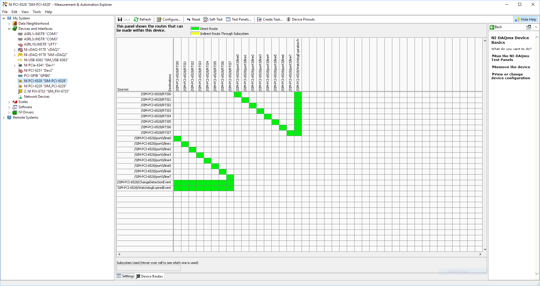
Using SMU 6612 to measure PXI-6528 pulsewidth channel - channel is not available.
Hi all
I use SMU 6612 card counter to measure the pulse width of the signals to PXI 6528 DIO card. These two cards are in the same chassis PXI (NI-SMU-1065). I could measure the pulse widths using the example LabVIEW 2013 Counter - pulse width of reading and (over) frequency example of .vi. However not all channels of the PXI-6528 map appear in the drop-down list of channels on the pulse width can be measured. Try to connect any other channel that those which are available in the drop-down list returns the error. On the PXI card port 6528 0,1 and 2 are entered ports and port 3-5 are output ports. I can measure the pulse on port 0, 3 width and line 0 port 1 and 4.
Can someone explain to me why don't see port 1 or port 2 channels in the drop-down list or force the VI to measure the width of pulse on these channels?
I can plug PXI-6528 external input channels SMU 6612 counter input channels and measure the pulse width, but if possible I'd like to avoid the external wiring between the 2 cards.
Probably not. Unless the routing plan is in fact reversed as it seems a bit sorta that. As stated on my system, you can route * of * a port of entry * to * RTSI, or you can route * of * RTSI * to * one output port. This does not make much sense to me, but that's what I see:
If the routing card * is * reversed, your only likely workaround without physical wire would be to generate impulses in question of port 3. It's pretty clear that 1,2,4,5-tetrachlorobenzene ports have no ability to interact with the bus timing, physical wiring would be the only option.
-Kevin P
-
PXI-1033 not detected until the pc is rebooted
We have a chassis NI PXI-1033 with a PXI-5114 and PXI-4072-PXI-6221, fist, that he had failed to recognize and install drivers for motherboards. The search in the knowledge base, I tried workaround by disabling the PCIe mode ' bcdedit/set pciexpress forcedisable' command and rebooted the pc. Then the system recognized and installed the drivers for all the hardware.
Disabled the PXI system at the end of the day. The next day, after activating the system, he did not recognize the hardware, returned changes to aid 'bcdedit/set pciexpress by default', then restarted the pc. Once again the material have been recognized.
I tried to change the configuration on the PC BIOS, without success. The PC is an ACP-4000 of Advantech. We need to restart PC after a cold start so he could recognize the hardware and load drivers.
Is this normal?
Concerning
The PC is under Windows 7 Pro. I searched on google for similar problems, where I found one where someone said that the culprit is that the chipset of the motherboard not give not the PCIe card delay what he needs on a start cold in order to be recognized. A reboot gives the time required and the card works.
-
Hello
I use a PXI-4070 DMM and DotNet "SoftwareTriggeredMultipointAcquisition" example
I want to trigger the DMM4070 with the AuxTrig entry to the front of the instrument.
This works very well, but how can I change the time out the of triigger?
It is now on 2000msec. I want to 10000msec.
When I us the example and do not trigger in the 2000msec I get error message saying:
ModularInstruments.NIDmm: The operation did not complete in time maximum allowed. Timeout: 2000mS.
Error code:-1074126845Thanks in advance
Wissam
Hello JaredRo
I can set the time-out period now.
Problem solved. Thank you Manny
With greetings
Wissam
-
PXI SFP 5105 configured Vs Acquisition VI
Hello
I recently started to use the NI PXI-5105 cards, I need to capture (noise level<20KHz) on="" top="" of="" my="" dc="" signal,="" i="" used="" software="" front="" panel="" to="" capture rising="" edge="" of="" an="" analog="" signal i="" was="" able="" to="" capture="" signal="" when="" it="" meets="" my="" trigger="" requirements="" same="" as="" configured="" acguisition="" example="" vi="" also="" vi="" recommended="" input="" signal freq="" ="" is="" 100khz,="" what="" changes="" i="" need="" to="" do="" in="" order="" to="" make="" this="" vi="" to="" trigger="" when="" the="" noise="" level="" on="" my="" dc="" signal="" exceeds="" certain="" point="" can="" anyone="" please="" help="" me="" with="" this="">
Thanks in advance!
Hey djo.
If I understand your description, the best sounds of relaxation as it can be a trigger of hysteresis with coupling AC trigger in order to eliminate the effects of your DC signal. You will then be able to adjust the amplitude of the noise that you are looking for as the level to which you want to trigger off. You can find information about the options available with the help of scanners trigger high speed OR under Fundamentals > trigger.
-
While with PXI-5122 digitizer loop counter
Hello world
I am a beginner of products NOR. Currently I use the PXI-5122, 2014 Labview for the ultrasonic signals. I have a problem when you count the number of signals using an external trigger (by a function generator) source. When I trigger the digitizer under 50 Hz, the meter is working properly (a single trigger = a signal). With a frequency greater than 50 Hz of trigger, the meter is malfunctioning. For example, with the shutter to 50 Hz and 500 number of signals, the counter takes 10s to get data. But, with the trigger of 100 Hz and 500 number of signals, the acquisition time was always around 10 s.
You can see the code in the file attachment.Please let me know if you have any suggestions or recommendations for my situation, I would appriciate that.
Thanks in advance!
Best regards
YouWorldALoneMe,
Looking at your code, you're software re - trigger your device. With your Setup, you configure the digitizer to hold a single record acquisition in your "A - Scan.vi". This VI opens the resource OR-SCOPE, configure, captures, returns the data, then closes the resource OR-SCOPE. It then does this for each unique A-Scan that you do and would be the reason that b Scan.vi takes so long. It appears then that fewer than 50 Hz, this reset any software and reconfiguration and the acquisition can occur without missing a trigger, but more than that, your triggers occur faster it takes to do these things.
What you need to do set up the digitizer to a multi-record acquisition. This is done using the 'niSCope configure horizontal timing.vi' and wiring in a number higher than '1' in the entry "number of records". "You can find an example of how to perform a multi-record acquisition if you open the Finder of example OR > material input and output > Modular Instruments > NOR-SCOPE > Getting Started > niScope EX Multi Record.vi.
In this example, the digitizer is only once configured, and it returns all the documents requested at the same time. For your application, each record would be a simple Scan of A, and then if you configure 500 files, your B-Scan would be 500 wide. This time allows the material to rearm between triggers that is much faster to do it in software.
For a verification of more complex example out (in the finder of the example) "niScope EX Multi record go get more available Memory.vi"
Kind regards
Nathan P.
Maybe you are looking for
-
These are the details. 21 FF does not work on my system, unless I choose Run as administrator. So far, none of the assumptions posted by your technical support on this issue in the past have worked. I removed the virus and removed FF and reinstalled.
-
How do you put the Journe Touch to sleep?
The documentation with the machine is hopeless, but it is another question. What I would do is to boycott the thing sleep, because otherwise you must close completely and it takes FOREVER to restart (despite BS in material claiming that it is "activa
-
When you press scan to e-mail function, error message below:SERVER CONNECTION ERRORThere was a problem connecting to the server. Press Retry to connect again, or OK to exit.When I retry, it won't work. Grateful if someone can advice here.Thank you
-
How to reset the graph of mixed signals automatically?
How do you resets a graph of mixed signals automatically? My idea is like that - I'm drawing a chart throughout the day... Then, at 19:00, I want the chart to erase. There will be a break until 06:00. It will therefore start a new graph at 06:00. How
-
Model #: s5212yProduct #: VT493AA-ABASerial No.: {removed privacy}Software Build #: 94NAv6PrA3Service ID #: 122-509PCBRAND: Pavilion I want to send an e-mail by clicking on the link on a Web site without signature on my personal email account and it