PXI-8532 vs 8461/D Devicenet master control
Hi guys,.
We bought two units of PXI-8461/D cards to control ABB robots. We currently plan on adding duplicates of the current system. I scoured online and realized that there is a new map for Devicenet, PXI-8532. After consultation with the local OR here, I've been advised to stick with the PXI-8461/D, as there are always limitations (lack of features) on the PXI-8532 - but he was not sure of what were the missing features. This is because the new PXI-8532 uses a new set of pilot (NI industrial Communication, instead of NOR-DNET). Is this true? If so, may I know what are the limits.
Please advice.
Thank you.
We made a few efforts to provide an upgrade path for these new devices with our version 2.1 now available for download. The only limitation as for now, it's that you can't have two types of devices on the same thing, which is controlled by the same VI. But you can run your old code with the new maps for example base. See this KB for the upgrade of your code.
We will soon publish the version 2.2 of the pilot which will add support for the slave, the last feature that was missing in regard to compatibility with the old driver. Let us know if you need a beta versionavailable to use the support of the slave already.
So in summary, if you are using the old APi master support, you should be able to duplicate your system and use the new cards instead.
If you are having problems please let us know.
DirkW
Tags: NI Products
Similar Questions
-
PXI-8532 DNET card is not detected in MAX
Hi all
I use NI PXI-1031(4 slot PXI chassis). I have the following cards in the respective locations
Slot 1 = controller PXI-8106
Slot 2 = PXI-6259 card (I)
Location 3 = card(DI,DO) PXI-6509
4 = Card (DNET) PXI-8532 accommodationMax (Measurement & Automation Explorer), I expect the cards above (PXI 6259, 6509 & 8532) to be detected under devices and Interfaces. But only cards and DIO are detected in MAX under deported systems > PXI > devices and Interfaces.
PXI-6259 (PXI1 Slot2)
PXI-6509 (PXI1 Slot3)The unit net card, PXI-8532 is not detected in Max MAX shows / detects the DNET card?
In MAX, I chose the menu Tools > NOR-DNET > RT Hardware Configurations. Then a window prompt you for IP address of RT. After you enter the IP address, I pressed OK. A message appears that no device is found.
Can someone help me how to detect card DNET in MAX and make the configuration of the port DNET?
DNET - 1.6.4 driver version
Thank you
RajaI try to answer two questions:
1. the new APUI is compatible with the former, but if you use screws with the old APi you need to replace the screws with the new. There is a white paper related to the download page and here it is again that explains how.
2. the devicenet driver does not yet support the plugin for the view of the PXI chassis. It appears under devices and Interfaces, and the name is not editable either. Currently the driver uses the numbers in the order of detection if several cards are present.
Two things will look in our next version before the end of this year.
DirkW
-
Effect of map to wipe Master Control.aex. Where can I get it?
I have after effect CC, the last of them. I noticed in the effects file, I have the effect of the Wipe.aex card but I do not have the effect of the card wipe Master Control.aex . Where can I get it?
It is a driving Pseudo-effet to a control of the expression, not a plug-in. Since you have not provided any info on what you are working on, we cannot give advice on how to solve this problem.
Mylenium
-
Micro-Star FX Master Control Board
Hi I need some advice on a Narcotics Control Master FX. mine is dead and I'm looking on eBay for new or second-hand? i ' v got these numbers from mine (DP/N - 0p0GVP - CN-0p0GVP-69702-9AQ-0805-A02). i ' v found that few with 0p0GVP but the rest are not completely upwards. i ' v got an auroa R1 high office if you need more info on this let me know. I need to know what to look for and all the numbers must match or be parts of other models adapt?
Fix. P0GVP sold on the Aurora-R1 and R2-Aurora. I said that earlier?
P0GVP = Master i/o Board, Non - ALX and Aurora-R1/R2-Aurora
http://www.txcesssurplus.com/servlet/the-7398/Alienware-Ms-DSH-4194-Aurora-FX/detailhttp://www.impactcomputers.com/p0gvp.html?filter_name=P0GVP
Look at the top of your system and compare the pictures.

-
Loudness Radar in Premiere Pro for master control
I can get LM (loudnss Radar) to work on individual tracks, but can it work by the master of output, also I thought you should be able to export your clips as an audio clip to go to the Auditions "such what" in a multitrack Setup, so you do not disturb your sequence and alignment settings, I can't seem to achieve this goal. Also in the timeline (PP) can choose several IE securities around the window in the program as a group rather than the individual.
Follow these steps


Hope that this is the case.
Peter Garaway
Adobe
Premiere Pro
-
Move to the foreground or background lacking in Muse CC 5.0 Master control?
I followed the tutorial "create your first website" using coffee Tute of Katie, which was built using Muse 4.0 & it refers to a new option to allow elements of a Master Page to be ' moved to > Master in the foreground. I use Muse CC 5.0 and can't seem to do it. I right click on the items I want to move & also went to object > move to? but none "moved to > Master plan ' it shows that ' move to > layer 1 ' or 'Bring forward', which is not what is not what the new option is supposed to do. Have they left it in Muse CC v5.0 & replace it with something else? or is mine defective and needs a fix (patch)?
Layer 1 is probably your Master Page items. You can move things around now by using the layers panel.

-
I use PXI - 1042 s with PXI-8196 embedded, each with several PXI modules installed controllers. (PXI-2530, PXI-4070 PXI-6509 etc..)
Is it possible to connect somehow to a laptop that has LabVIEW installed, such that I can develop applications (on the laptop) to control PXI modules?
When applications are completed and compiled in executable files, they will be installed on the PXI controllers.
I don't want to do, is to install LabVIEW on each PXI controllers I have to develop applications.
Kind regards.
You can develop your application... virtually simulating PXI modules - sounds interesting, but how to do this? (Or is it a matter for another post?
To simulate the device go to MAX > right-click devices and Interfaces > NOR-DAQmx simulated device > select your device and enter ok.
... but if you were to buy a PXI MXI-Express kit you can remotely control the PXI chassis - I think that's what I was looking for. But wouldn't this "work around" the on-board controller and have the executable running on the laptop instead? Looking at the link you posted, it is worth further investigation
It will bypass the controller for development purposes, but when you have generated your executable you can just charge on the PXI controller and it will run without the need of the laptop.
Kind regards
-
Where is the main stream of photos of iCloud control?
I use the iPhone, iPad and iMac. I have my iMac (desktop interface) a "Master Control" of sorts so that when I delete something, it's really gone. Before iCloud, I used to manually import my iPhone photos into iPhoto, the original deletion and manage my collection in there before synchronization to update. Now in El Capitan, I use Photos (as suggested), but I'm not quite clear on the deletion/removal photo process.
In my experience repeated, when I delete the pictures, my other devices seem to keep. If I have my iMac to remove a photo taken by my iPhone, is & t photo be removed only from the cloud and not from the original unit? Perhaps I am being too impatient?
If you use iCloud photo library, then all changes made on any device, including changes, additions and deletions are made on all devices - thi does not work until all devices have finished their initial download
No one is the master - all are equal
LN
-
LabVIEW 2014 SP1, hardware and real-time PXI
I'm doing my third LabVIEW Wipe/reinstall in as many days, completely frustrated (and after several calls an hour with the support of NEITHER). Here's the situation:
I wrote a fairly large (1000 VI) project of Acquisition/control of our graduate students data used for behavioral experiment on sound localization. It was developed in 2012 LabVIEW with the module running on a PC/PXI system real time. It worked very well and was brought successfully under LabVIEW 2014 (with upgrades comparable to the software of the PXI.
About 18 months ago the students began to write their theses, and at one point stopped gathering data. Also, at some point, I upgraded the software on this system to LabVIEW 2014 SP1, but I am not sure that I never tested my software with this new system.
This week, I pulled up the system to use MAX to open some test on the PXI multifunction and DIO card panels to control manually one of the stimuli. I discovered that MAX could not communicate with the advice on the PXI system - he attributes them as devices VISA, indicating each Board with an icon with a red X means that he could not communicate with the IP that I had assigned to PXI. Yet, MAX (a) could "discover" this PXI, (b) MAX can 'see' its IP address, and (c) Windows could not only Ping the IP, but could FTP on the drive of the PXI and I could move files back and forth.
I did two sequences complete "Wipe/reinstall" using LabVIEW 2014 SP1, all giving the same result. I know it has worked in the past, including when I installed LabVIEW 2014 (without SP1), something I repeat myself now with my third installation. I discussed with OR (thin?) possibility that there is a "hidden defect" in the Distribution of the SP1, one that is visible to LabVIEW RT users using PXI hardware and go unnoticed because (a) install a few sites of LabVIEW versions SP1, (b) a minority use the RT Modules and (c) PXI is "old material".
If anyone has such a system or saw a similar problem, please answer. I'll do a follow-up post if I managed to 'fix' my system by this last reinstallation "a solution of worked before."
Bob Schor
Well, the answer is that, in my system, LabVIEW 2014 SP1 with LabVIEW Real-time connected to a PXI system does not appear to connect to boards plugged into the chassis. Returning to LabVIEW 2014 (fall release), installed in exactly in the same way that the three failed attempts of LabVIEW 2014 SP1, works immediately. Engineers OR will try to duplicate/verify/possibly patch? in this issue.
Bob Schor
-
Hi all
I would like to create a button custom as a master, so that if I change the look of the master all other buttons are changed.
I did it with a custom control, such as a 'type strict def' otherwise the look will change , BUT if I do this as a strict type def I can't change the Boolean text more which should be different on each button.
How to create a master control of a button where the look apply to everyone else but not the Boolean text?
Steve Chandler wrote:
I don't think that you can do. I just looked and as I suspected the Boolean property text is read only for strict typedefs, you cannot use the nodes property to change the text.
As a just solution make it a typedef. When you want to change the open look the typedef and strict rendering, make your changes, then make no strict again. You will need to update the text Boolean yet once for all instances. Kind of pain. This is perhaps something for the exchange of ideas.
Alternatively, remove Boolean text and replace with legend
-
How do I get the name of a duplicated or created control and add a reminder
Hi all
According to the number of entry points I need, I duplicate a digital or an input string to the DuplicateCtrl function. My question is, how do I get the name and id of the control that has been created, and how can I assign a callback to it? Alternatively, it would be better to create a fresh ctrl instead of duplicate?
Thanks in advance!
Hi TurboMetrologist,
Why are you trying to get the name of constant control? Remember that you cannot use this name to address control; control names are in fact simply the macros in the file associated with the UIR, include in other words, the preprocessed compiler code and everywhere where the names of PANEL_CONTROL replaces the digital value as parameters to functions (and therefore 'control' parameter is an int value and not a char *)
That's why NewCtrl () or DuplicateCtrl () functions return a control ID: this is the handle to the new object, the only way to handle it. You will need to store this handle in a nonvolatile memory so that you can access durng life program.
In addition, there are other ways to assign a meaning to a control to pass on the name of constant control. For example, you can use the callbackData parameter to differentiate the different copies of a control.
Let me explain with an example. You said that you need several entries (dynamically created that you don't know in advance how many of them use); a solution could be:
- Design a master copy of a control in the IUR Editor, where it is easy to customize; also assign a callback function, if it must be common to all copies of the control
- Assign a value to this control callbackData, programmatically for example SetCtrlAttribute (...,..., ATTR_CALLBACK_DATA, (void *) 1);
- Duplicate the control, and then assign a different callbackData
for (i = 2; I have< 5;="" i++)="">
handle = DuplicateCtrl (...);
SetCtrlAttribute (..., handle, ATTR_CALLBACK_DATA, (void *) I);
}
By operating this way, whenever the reminder of control is triggered by any control, it will receive the callbackData assigned, and you will be able to differentiate your code with a simple switch:
switch (callbackData (int)) {}
case 1: / / the master controls
break;
case 2: / / first dual control
break;
}
-
Control PLC Modicon-Quantam of Modbus TCP/IP Ethernet.
Has anyone use LabVIEW to program a PLC Modicon-Quantam successfully using Ethernet TCP/IP? I tried the examples MB Ethernet (master/slave) in the download nimodbus121 and it doesn't work. I really need to know the best way to connect and communicate to a PLC Modicon-Quantam using LabVIEW, Ethernet Modbus TCP/IP using the Excel spreadsheet. I need to write entry registers (write) shift in and read from holding registers. The software that I SMTX Modbus/TCP Master control ActiveX does not completely for me. I can ping to the controller from cmd prompt. I saw this webcast - creating a server of e/s Modbus TCP with the LabVIEW Datalogging and supervisory Control Module 8. I've also seen a webcast on OLE for process control (OPC). What should I write LabVIEW control and view records by using LabVIEW flags? Someone at - it a LabVIEW example that I can start with? Should I buy the DSP module for $1280,00? This will solve my problems?
If you have found return data that you do not understand that I recommend trying to send output known of the automaton at least to determine what kind of conversion has to happen. This document talks about the Optomux protocol that can be used with programmable automata. You will need to find specific documents that tells you how to convert these data into LabVIEW. You can also start a new forum, since this is a separate issue from the original.
-Hunter
-
Alienware Aurora ALX lights does not work master of e/s part #.
I tried to get the lights on my Alienware Aurora ALX job. The only lights that works are the head alien and the flange. Work, I mean that they are white. When I Command Center, it doesn't even show fan/readings of temperature or light speeds. I think that my I/o card is bad.
I can not get something to change in Comand Center.
I tried all the solutions on the forums and nothing seems to work.
I reinstalled windows 3 times. Nothing.
I reinstalled Alienware Command Center 6 times (correct version and the different)
I tried shutting down the computer, unplug the power cord and hold the power button for 1-2 minutes thing, didn't work.
I went to reset the map using the Green rider, did not work.
I ran a diagnosis and everything seems fine, don't know if it's testing the Master Control I/O Board.
I'll order an Alienware Aurora ALX Alien FX / Master Control I/O Board, because I am sure that my i/o board is bad.
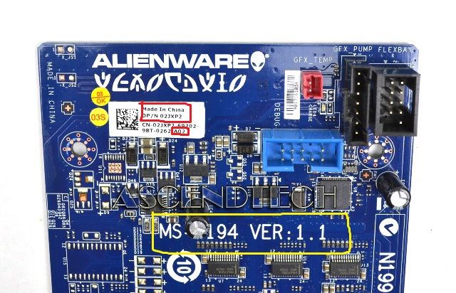
The reference is 02JXP2 and version 1.1 mine said A02
The white mark on my map of IO said A02, but it has the same part number 02JXP2 and version 1.1.
My question is can I use a Board with the same part number but it says A04?
Here is a picture of the map of IO with the A02, I want to buy a economy part number 02JXP2 and at the bottom says A04 instead, but is a version 1.1.
If anyone as any advice before ordering the card / advice to see if I can get the lights work on my computer?
ThatOne_GamerI don't have the cable that connects the motherboard to the MIO card.
I'm sure that's why my ect lights do not work.
Right... If it is not connected, it cannot work.
-
dbenv-> txn_checkpoint can't finish the master HA
BDB dear gurus,.
I tested my HA with bdb4.6.21 api base code. Every minute, I started a pthread dedicated for control points. The thread checkpointing feature is as below:
for (; sleep (WRITE_CHECKPOINT_INTERVAL)) {}
If ((ret = dbenv-> txn_checkpoint (dbenv, 0, 0, DB_FORCE))! = 0) {}
trace (TRACE_LEVEL_INFO, "%s: write checkpoint failed for %s.\n", __FUNCTION__, db_strerror (ret));
}
trace (TRACE_LEVEL_INFO, "% s: writing checkpoint %s.\n", __FUNCTION__, db_strerror (ret));
RET = dbenv-> log_archive (dbenv, NULL, DB_ARCH_REMOVE);
If {(retired)
trace (TRACE_LEVEL_INFO, "% s: log_archive failed to eliminate newspapers %s.\n", __FUNCTION__, db_strerror (ret));
}
}
When I run my code without env DB_INIT_REP Pavilion, the control point and autoremove works. And I got the track ' write the successful return of control point: 0 ".
But when I run my code with DB_INIT_REP set and a single master, a replica, it seems that the function txn_checkpoint call never returns. Backtrace from gdb to the thread of control point can be seen below:
#0 0x00007fa59f92d033 in select() to... / sysdeps/UNIX/syscall-template. S:82
#1 0x00007fa59ff128c5 (/usr/local/BerkeleyDB.4.6/lib/libdb-4.6.so __os_sleep)
#2 0x00007fa59ff1bd94 (/usr/local/BerkeleyDB.4.6/lib/libdb-4.6.so __txn_checkpoint)
#3 0x00007fa59ff1c0f0 (/usr/local/BerkeleyDB.4.6/lib/libdb-4.6.so __txn_checkpoint_pp)
#4 0 x 0000000000404288 in xxx (arg = 0xc0d010) at xxx.c:1776
#5 0x00007fa59fc06e9a in start_thread (arg = 0x7fa59bda4700) at pthread_create.c:308
#6 0x00007fa59f933ccd in clone () to... / sysdeps/UNIX/SysV/Linux/x86_64/clone. S:112
#7 0 x 0000000000000000 in? ()
How can I proceed?
Thanks, Min
I guess that your thread of control point is executed on your master.
The call to __os_sleep() is planned at a control point on the master. Control points can take a long time. When a master does a control point, registration for this control point is sent to the customer and the customer must also make a point of control. It is possible that the customer might have different hardware or features I/O causing sound control to take much longer than the control point. So we wait for extra time after a master control station to allow customer checkpoint complete. This allows to improve the ability of the client to follow the master.
You can control the amount of overtime that wait us after the master control with the time-out DB_REP_CHECKPOINT_DELAY point that you can set with the call to DB_ENV-> rep_set_timeout(). The default value for DB_REP_CHECKPOINT_DELAY is quite long - 30 seconds. If you make the control points every minute, you probably want to reduce this time-out value.
Paula Bingham
Oracle
-
LabVIEW interface with multiple blocks of Festo module
I am trying to connect with a block of Festo, but I can't. Here are the details:
I'm under Labview 2012 SP1 with IndComm-DeviceNet 2.2 pilot on a 64-bit Windows OS. I installed a PCI 8532 card NOR. I see the map to the MAX.
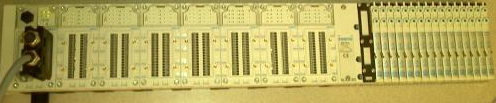
The block of Festo is built with the following Modules: CPX_FB11 (communications module), 4 analog input Modules, 1 Digital module, 2 digital modules followed by 32 Festo valves. (Image below)
Using DeviceNet PXIPCI Basics.lvproj I did the following:
In the project, right-click on desktop > New > targets and devices > existing target or device, discover an existing target or device...
Expand the node of DeviceNet Master Interface, DeviceNet1 chosen and added to the project.
A click on the newly added DeviceNet/device target > New > targets and devices...
Expanded the Festo Block "CPX_FB11" selected DeviceNet slave device and added to the project.
Initially, I received an error card technique 'EDS file no assigned' I solved this by following the direction listed here.
However, I'm unable to "see" anything other than the CPX_FB11 LabView. The tree view of the devices lists not analog, Digital e / s or valves. I can't operate the Valves and IOs digital or analog. When I run the entire project VI they then expire.
Any help would be appreciated.
Thank you
Tennessee Paul
Hi Jesse,.
I'm not entirely sure what the specific problem was. I kept getting strange behavior. Errors in LabView and on my camera from Festo. The EDS files change. So, I did as any natural born THERE would be worker, I rebooted.

Here are the steps I used to get this project going. In doing so, I found that to set up a DeviceNet device in LV2012SP1, no need to manually enter the data in file EDS. There is a tool to load files EDS. It dealt with issues I had in the previous Forum posts: here about loading files EDS in LabView and here regarding setting up a DeviceNet network.
Environment: Windows 7, 64-bit processor. IndComm 2.2 pilot. LabVIEW 2012 SP1
Starting with the example LabView project: "Devicenet PXIPCI Basic.lvproj.
Add a DeviceNet master to a LabView project
- The project: right-click on my computer
- Select new
- Select the targets and the device (s)
- Select the option "discover existing devices.
- Select the discovered device.
- Click 'OK' (Note: in this case, my master is a card PCI of NOR-8532)
Add a DeviceNet slave device to a LabView project
- Right-click on the master device newly added in the project tree
- Select new
- Select the targets and the device (s)
- Select 'discover existing devices.
- Select the discovered device.
- Click OK. (Note: in this case my slave is a block of Festo CPX-FB11.)
Load an EDS file to the slave device
- Right-click on the slave device
- Select "Sheet"... »
- Click on add files...
- Navigate to the location of the EDS file.
- Select the file.
- Click OK.
- In the left pane, expand the data sheet newly added up to reach the node displays the version.
- Select the version.
- Click OK.
Check the device and file EDS
- Right-click on the slave device
- Select utilities
- Select the Panel of Test online
- Select the option 'Device status' in the field of category on the left.
- On the right, select the slave device, you want to check.
- Click on "check the device".
- Read the errors/warnings or lack thereof.
- Navigate to the following location: C:\ProgramData\National Instruments\NI-IndComm for DeviceNet\Datasheet
- Remove the sheet (Note: there is more that one datasheet added manually.) Additional EDS files come with the IndComm driver. Find the EDS file for the specific device that you want to replace and delete).


In my case I had errors in my EDS file. Basically the slave device was not defined for the correct number of bytes of input/output in the EDS, i.e. a wrong configuration file. To fix this I had to change the EDS file.
Edit the file EDS
To change the EDS file, I used EZ-EDS , which is a freeware, devicenet specific EDS editor of ODVA.
I did my corrections and saved my file EDS. (After having saved my original, of course).
Remove the installed Labview EDS file
I restarted LabView.
I went through the steps above again and loaded my new EDS file.
I saved the project and came out of LabView.
I rebooted the computer and the slave device.
I restarted the project and launched a VI.
I was able to communicate with the device. That is something that I had not been able to do before. And, in doing so, I discovered how the device speak and why were not each module. (I have a standard for my block devices EDS file, as it appears that LabVIEW is not capable of a modular system that requires an EDS file for each module. I could be wrong on that last part though, as there may be a setting on my real device. But it is unecssary in my project. So I do not consider this further.) Because I was using a standard file of the EDS, only a single slave device showed, and so the data for each module are in the stream of bytes returned to the DeviceNet network. Addressing each module is a question of analysis the bits and the bytes appropriate.
Thank you
Tennessee Paul
Maybe you are looking for
-
Firefox browser will let me see all the info site. other browser does.
Key information are not loaded on my banking site using Firefox as my browser. When I contacted my bank they asked to use Internet Explorer and the browser loading all the information requested. My Bank suggested that contact Firefox to correct the p
-
Hello In my application, I was able to send 3 messages CAN at the same time on CAN bus. I donot want to use timestamp, this means that all three messages should be transmitted immediately. But I'm a gatting error Error code:-1074388982 Description:-N
-
Wie kann ich das Foto auf der Seite once winds?
Beim Login, neben der Mailadresse möchte ich das Foto winds. Nur wie geht das? Danke fur den remark
-
Due to the Style battery drain cover Widget
I bought the Style cache for my Z3 Compact. Widget Style of coverage has been installed automatically once the phone has been "twinned" with the lid using the NFC. In some situations, I do not use cache-Style and strange things begin to happens - I l
-
A copy of the eligible US Original manufacturer's warranty
Hi HP laptop owners: I bought a laptop HP Pavilion TX1215NR on August 14, 2007. The LCD screen has just stopped working a few weeks ago and manufaturers on laptop warranty expired in August 2008. I'm trying to make use of the additional protection of