LabVIEW interface with multiple blocks of Festo module
I am trying to connect with a block of Festo, but I can't. Here are the details:
I'm under Labview 2012 SP1 with IndComm-DeviceNet 2.2 pilot on a 64-bit Windows OS. I installed a PCI 8532 card NOR. I see the map to the MAX.
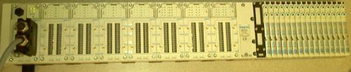
The block of Festo is built with the following Modules: CPX_FB11 (communications module), 4 analog input Modules, 1 Digital module, 2 digital modules followed by 32 Festo valves. (Image below)
Using DeviceNet PXIPCI Basics.lvproj I did the following:
In the project, right-click on desktop > New > targets and devices > existing target or device, discover an existing target or device...
Expand the node of DeviceNet Master Interface, DeviceNet1 chosen and added to the project.
A click on the newly added DeviceNet/device target > New > targets and devices...
Expanded the Festo Block "CPX_FB11" selected DeviceNet slave device and added to the project.
Initially, I received an error card technique 'EDS file no assigned' I solved this by following the direction listed here.
However, I'm unable to "see" anything other than the CPX_FB11 LabView. The tree view of the devices lists not analog, Digital e / s or valves. I can't operate the Valves and IOs digital or analog. When I run the entire project VI they then expire.
Any help would be appreciated.
Thank you
Tennessee Paul
Hi Jesse,.
I'm not entirely sure what the specific problem was. I kept getting strange behavior. Errors in LabView and on my camera from Festo. The EDS files change. So, I did as any natural born THERE would be worker, I rebooted.
Here are the steps I used to get this project going. In doing so, I found that to set up a DeviceNet device in LV2012SP1, no need to manually enter the data in file EDS. There is a tool to load files EDS. It dealt with issues I had in the previous Forum posts: here about loading files EDS in LabView and here regarding setting up a DeviceNet network.
Environment: Windows 7, 64-bit processor. IndComm 2.2 pilot. LabVIEW 2012 SP1
Starting with the example LabView project: "Devicenet PXIPCI Basic.lvproj.
Add a DeviceNet master to a LabView project
- The project: right-click on my computer
- Select new
- Select the targets and the device (s)
- Select the option "discover existing devices.
- Select the discovered device.
- Click 'OK' (Note: in this case, my master is a card PCI of NOR-8532)
Add a DeviceNet slave device to a LabView project
- Right-click on the master device newly added in the project tree
- Select new
- Select the targets and the device (s)
- Select 'discover existing devices.
- Select the discovered device.
- Click OK. (Note: in this case my slave is a block of Festo CPX-FB11.)
Load an EDS file to the slave device
- Right-click on the slave device
- Select "Sheet"... »
- Click on add files...
- Navigate to the location of the EDS file.
- Select the file.
- Click OK.
- In the left pane, expand the data sheet newly added up to reach the node displays the version.
- Select the version.
- Click OK.
Check the device and file EDS
- Right-click on the slave device
- Select utilities
- Select the Panel of Test online
In my case I had errors in my EDS file. Basically the slave device was not defined for the correct number of bytes of input/output in the EDS, i.e. a wrong configuration file. To fix this I had to change the EDS file.
Edit the file EDS
To change the EDS file, I used EZ-EDS , which is a freeware, devicenet specific EDS editor of ODVA.
I did my corrections and saved my file EDS. (After having saved my original, of course).
Remove the installed Labview EDS file
- Navigate to the following location: C:\ProgramData\National Instruments\NI-IndComm for DeviceNet\Datasheet
- Remove the sheet (Note: there is more that one datasheet added manually.) Additional EDS files come with the IndComm driver. Find the EDS file for the specific device that you want to replace and delete).
I restarted LabView.
I went through the steps above again and loaded my new EDS file.
I saved the project and came out of LabView.
I rebooted the computer and the slave device.
I restarted the project and launched a VI.
I was able to communicate with the device. That is something that I had not been able to do before. And, in doing so, I discovered how the device speak and why were not each module. (I have a standard for my block devices EDS file, as it appears that LabVIEW is not capable of a modular system that requires an EDS file for each module. I could be wrong on that last part though, as there may be a setting on my real device. But it is unecssary in my project. So I do not consider this further.) Because I was using a standard file of the EDS, only a single slave device showed, and so the data for each module are in the stream of bytes returned to the DeviceNet network. Addressing each module is a question of analysis the bits and the bytes appropriate.
Thank you
Tennessee Paul
Tags: NI Products
Similar Questions
-
LabVIEW interface with micro contoller
I'm new to labview. I need to know if the DAQ card is necessary to interface with micro controller? If no need then one can you explain how inter face microcontroller 89c 51 with Labview... If necessary, explain how interface?
JEAN ASOKAN
-
How to use the Shell of the user interface with multiple applications (ear)
I use 11.1.1.6 JDeveloper.
I want to modularize the functionality in applications (ears) and use the Shell of the user interface as a navigation mechanism between applications and single entry.
Is this good?
What is the use of Shell of the user interface best practices.
What about security (2 AA)? Security of the ADF?
Thank you
Hi user,
You can use the shared library ADF function if you would like more information
http://andrejusb.blogspot.AE/2010/07/deploying-ADF-applications-as-shared.html
use the adf security
-
On a NI USB 4432 device, any C++ APIs, interface with C++ application module.
1.C ++ API - can I interface with the NI USB 4432 through a C/C++ application, she api C/C++ or dll.
Need to get the entry/signals of the module in a C/C++ application.
2. compatibility - information of the BONE, is the product drivers Windows XPE (XP Embedded) compatible?
3. any link/site for documentation full on the moduleYou must use the NI-DAQmx driver
-
Change the path open the initial sequence of the operator Simple of TestStand with LabVIEW Interface
Hello
I use an Interface with LabVIEW TestStand operator similar to the TS IO Simple example.
But I want to change the path when you click the button open the sequence file, I want a specific path.
Any help is apreciated.
Kind regards
Daniel Coelho
Daniel, you might be interested by this Knowledge Base:
How can I change the default directory for the open file dialog box in TestStand?
I searched ni.com for teststand of dialog box open the file and it was the fifth or so link.
-
problem with a block of memory in labview 2009
Hi all
I have "ERROR: MapLib:979 - LUT4 symbol" during the compilation process (lots of errors like this), and I discovered that the reason of my problem is block of MEMORY.
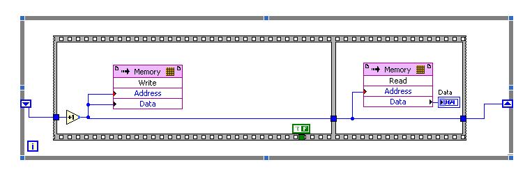
To be sure that the problem is in this block, I did a very simple project in LabView 2009 (on FPGA Target PCI5640R) only with the use of this block you can see in the photo, as well as in file test_memory block.lvproj attached link: https://www.dropbox.com/sh/u87f1oihelmm4dq/Jo_6-bICSf
I have a problem with compiling VI with this block, and I have so many errors like:
ERROR: MapLib:979 - LUT4 symbol
"window/Thatcher/n_00000036/nSCTL_00000013_00000014/n_000000A3/cOutLoc<0>1.
(output = window/Thatcher/res000001ed_wi<2>) is the input signal
"window/Thatcher/res0000020d_wo<1>" that will be deleted. See Section 5 of the
Map a report file to find out why the input signal will become conveyors.or
ERROR: MapLib:978 - LUT4 symbol
"window/Thatcher/n_00000036/nSCTL_00000013_00000014/n_000000A3/cOutLoc<23>1.
(output = window/Thatcher/res000001ed_wi<25>) is an equation that uses
input pin I2, which no longer has a connected signal. Make sure that all the
the pins used in the equation for this LUT are signals that are not cut
(see Section 5 of the report file map for details on which signals were
adjusted).Entire report, you can see in the file report.txt on the attached link.
I would appreciate if someone could take a look at my problem with simple project and suggest me a solution.
I'm really stuck with my biggest project which need to have this memory block.
I'm looking forward to hear from you,
King looks
ING. Damir Hamidovic
Hi all
I find a sollution to my problem.
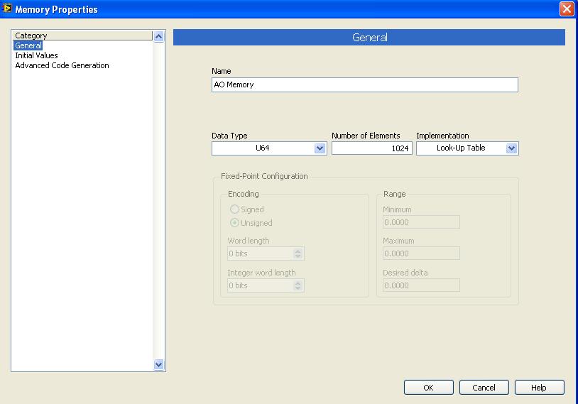
In memory-properties-general-setting up, I changed the block to look up Table memory, and I compile memory.vi and run it successfully.
I did change as you can see on the picture:
Just, can you tell me is it all "bad properties" and limits the use of this type of memory (Look up Table) of the implementation?
King looks
-
Any camera regardless of the interface is available for use with the LabView interface.
Hello
I intend to go for some CMOS camera,
but I have a huge doubt before buying, the camera of menttioned above is not anywhere in this list. Nor can I see any type being supported USB device.
The question is
- is a camera regardless of the interface is available for use with the LabView interface?
- Can I build a VI to communicate with any device image and recording of camera and take the data?
Any kind of help or advice is greatly appreciated... I have to buy a CMOS camera and begin to run.
Thank you...
Hello Virginia,.
I am pleased that this information has been useful, one thing I wanted to mention is that USB 3.0 has its own standard USB 3.0 Vision which is currently not supported. If this camera is also Direct Show compatible then you will be able to acquire an image using IMAQdx and manipulate all the attributes that are published to the API Live Show.
I hope that USB 3.0 Vision will be supported in the near future, and we tentatively announced for this standard of communication for the August 2013 Vision Acquisition Softwareupdate.
See you soon,.
-Joel
-
A module C - DAQ exists which will interface with standard RV - C?
Module C - DAQ exists that if interface with standard RV - C (vehicles recreational CAN)? RV - C seems to be a variant of J1939 according to Wikipedia.
I would use 9861 OR or NI 9862. I'm new on CAN protocol and evaluate some assistance.
I've never used RV - can, but according to Wikipedia, the rate is 250Kbaud, so you'll want high speed CAN peripheral, 9862, you can set baud rate on init of the material. After installing XNet and cDAQ software, you have a max bus monitor and several examples in the example Finder to read and write raw images. After that, you'll want to read on the standard to understand how to format and analyze the data.
Also if you have any questions, you can post on the Sub-forum Auto , they can probably answer more specific questions.
-
4235 with multiple monitoring Interfaces?
This is a general question as to whether anyone is running on 4.0 4235 sensor code with multiple monitoring interfaces?
Basically, I wonder if you have any comments on the performance or if you run into any problems with the configuration. I have not seen too much documentation for configuration in fact this, so I wonder if there are additional requirements or considerations.
Hi Chad,
With ID 4.0, you can only montior using an interface to sniff. 4.1 you will have taken care of multiple monitoring interfaces.
As far as performance goes, I don't see any problems and more to ensure that the management station is able to handle the upcoming alarms when using several interfaces.
Thank you
Obaid.
-
Easy VPN setup with interface to multiples with the same level of security
Hello
I want to configure an ASA 5505 with 7.2 (4) software and dual license ISP and when I configure two interfaces with the level 0 on two security interfaces and enable vpnclient the trace message appear:
ERROR: Cannot determine the internal and external interfaces Easy VPN remote: multiple interfaces with the same levels of security.
vpnlclient of configuration above:
vpnclient Server x.x.x.x where x.x.x.x
vpnclient mode network-extension-mode
vpnclient nem-st-autoconnect
vpnclient TUNNEL_EZVPN_TUNNELSPEC vpngroup password *.
vpnclient username usr_ezvpn_tunnelspec password *.
vpnclient enableinterfaces:
interface Vlan200
nameif outside1
security-level 0
IP x.x.x.x 255.255.255.252
!
interface Vlan300
nameif outside2
security-level 1
IP x.x.x.x 255.255.255.128
!monitor the SLA to the routing:
monitor SLA 100
type echo protocol ipIcmpEcho 200.221.2.45 interface outside1
NUM-package of 5
frequency 30
monitor als 100 calendar life never start-time now
ALS 200 monitor
type echo protocol ipIcmpEcho 200.154.56.80 interface outside2
NUM-package of 5
frequency 30
Annex monitor SLA 200 life never start-time now
ALS 300 monitor
type echo protocol ipIcmpEcho 4.2.2.1 interface outside1
NUM-package of 5
frequency 30
Annex monitor SLA 300 life never start-time now
ALS 400 monitor
type echo protocol ipIcmpEcho 200.244.168.149 interface outside1
NUM-package of 5
Timeout 3000
threshold of 3000
frequency 30
Annex monitor SLA 400 life never start-time nowFollow-up:
!
track 1 rtr 400 accessibility
!
Track 2 rtr 200 accessibility
!routes:
Route 0.0.0.0 outside1 0.0.0.0 x.x.x.x 100 track 1
Route 0.0.0.0 outside2 0.0.0.0 x.x.x.x 200 track 2The track works normal.
Kind regards!
Try using the command "backup interface" on the secondary ISP interface.
http://www.Cisco.com/en/us/docs/security/ASA/asa72/command/reference/b_72.html#wp1338585
You need to increase the level of security to 1 for this interface.
By default, EasyVPN uses the highest level of safety inside and the lowest outside. Anything between the two must be set manually. I assume you have an interior vlan defined but not added to the posted config.
-
Using NI 9870 with drivers of the robotic Module
Hi all
I am using quite a few sensors that are supported by the LabVIEW Robotics module (GPS, MIO, compass and probably a LIDAR soon.) However, I would really like to be able to use the module series OR 9870 RS - 232 in a CompactRIO to interface with these devices (currently they are connected directly to a PC.) Unfortunately, I do not know if there is a way to do it without having to rewrite the drivers for the FPGA. Someone has encountered this before or maybe knows a way I can do this without reinventing the wheel? Thank you!
Brandon
BrandonGT,
Worked on a similar problem. Take a look at this example . Note how the service contact numbers is used to add an identifier to the data before it is put into a common FIFO.
-
How do I program labview to read all 8 compact fieldpoint modules?
I am new to fieldpoint and I my set-up block diagram to read 8 strain gauges using a SG-140 module. My basket is filled with strain gauge modules 8 SG-140, and I need to know how to fix my diagram to read all 8 modules of SG - 140. So, I need a total of 64 strain gauge readings 8 modules of SG - 140. Can I do this without really copying what I've already done 8 times more? Is it possible to use a loop or something to read the 7 other modules? I appreciate any help I can get.
My opinion about not having to duplicate the table of index based on what your VI was showing at the time. Once you have the VI implemented with multiple modules, then you will need to implement an array of unique Index stretched far enough to get all the channels of interest. From a 2D array, you need to connect both the row index and column index for a single scalar element. So first channel would be 0 and 1, then 0 and 4, canal next 0 and 7. The next module would be 1 and 1, 1 and 4, 1 and 7.
-
Generator interface user Web supports the DSC Module?
A simple question:
Can I use the generator of the user Web interface for Web client access to a Windows-LabVIEW System with the DSC module or supportet has this tool user interface only the LabVIEW base for the objects in the front?
For example: Can I use a web client to review historical data and alarms? Can I use a web client with full support for "The front panel security dialog box" (see http://zone.ni.com/reference/en-XX/help/371618F-01/lvdsc/front_panel_security_db/)?
Best regards
Frank
Hi Frank,.
Yes, you can use the generator of the user Web interface to access historical data and view the current alarms. The LabVIEW 2010 version of the ASN has several built-in RESTful web services that make the Citadel and alarm available via HTTP data. Here are some resources to provide details on how it works.
Interact with Web Module DSC Services
Here is an example that illustrates how to implement web service at the Citadel communication:
Communication of data via Web Services in the Web of LabVIEW user interface Builder
Kind regards
Mike
-
Problem calling LabVIEW DLL with c#
Dear all,
I compiled a few DLLs in LabVIEW and called these DLLs using c#.
I'm having trouble passing in strings and arrays as input and output of the DLL.Whenever I try to view the string I have entered in a dialog box (this part is written in LabVIEW DLL), a LabVIEW message dialog box appears and the program just stuck there.
Whenever I try to enter a string or an array to the dll, Microsoft Visual Studio would display "attempt read or write protected memory. It is often an indication that other memory has been corrupted. »
I attached the vi and also the c# .sln file.
Can you guys please advise where am I wrong?
Thank you very much.
You must allocate strings and arrays of output!
private void button1_Click (object sender, EventArgs e)
{
output string;
int [] value;
StringOutput ("A", "B", exit, 3, value, 4);
}
}Your variable output and value must be preallocated to ensure storage of 3 items respectively. 4. and since you want to receive the C string that you need to increase this to 4 characters terminated by a NULL value.
String in c# is also a not a C string of object pointer. You must declare the StringOutput() function as follows:
[DllImport("SharedLib.dll",CallingConvention=CallingConvention.StdCall, Charset=CharSet.Ansi]internal static extern int StringOutput(StringBuilder A,StringBuilderB, outStringBuilderStringOutput, int sizeString, out int[] output, int sizeArray);Then call like this:
StringBuilder output = new StringBuilder(4);int[4] array = new int[4];

StringOutput("A", "B", output, output.Capacity, value, value.Length);
Please note that I'm not a pro in c# and usually do not do much in it. Also that this code has not been tested or updated at all, so probably contains some errors. He however point you in the direction of where to look further.
What you need to understand, is that the C DLL that you created in LabVIEW has a so-called unmanaged interface. This means c# is not able to know how to manage the memory for the parameters at all and you have to do everything yourself, where the obligation to explicitedly initialize variables output and table with a block of memory préallouée.
-
I use pci-6221, I need her to interface with thermocouple with voltage up to 5v
I use as my pci-6221 or data acquisition card and card 8.2.this labview version gives the constant 10.5 volt signal in at the entrance to analog channel AO on pin 68 and 34. why it shows 10.5 although I did not connect any input.i use type k thermocouple and after signal conditioning with tl0804 I need it interface with AI 0.i channel unaware aware of off the road on the output pins this Card.i need to operate an electric rod that needs 24 volt DC.i give entry to the pins HAVE with variable dc power block after reaching the limit I set(eg:2v) it jumps instantly to 10.5 volts.
You have your task to acquisition of data configured for the mode differential or asymmetric acquisition for the analog input?
I don't understand your comment about to connect the pins WITH a DC power supply. Why is that you connect a DC power supply to the analog input?
Using an analog output or digital output to operate the electric rod? I'll assume that you are looking for on/off control. A digital output is not the voltage or current to drive something that big. You may be able to find a relay for coil 5VDC. Check current requirements. With which you can have the relay to connect or disconnect a power supply of 24 VDC is the actuator. Make sure you have a protection diode across the relay coil wired, so that the magnetic field of the coil does not damage the analog output of your card.
Another possibility is to have the 5 VDC output transistor circuit switches the 24 VDC circuit.
Maybe you are looking for
-
lost my admin password password window but the reset doesn't show any volume!
For some reason, I forgot my administrator password. On my MacBook Air, I have two accounts, one is the administrator, which I can access is no longer, and the other is my usual which I can access, but I can't unlock settings on this subject because
-
Scanner not detected on HP #6310? How to scan?
Scanner not detected on HP #6310? How to scan?
-
I have a dell windows xp installation disc. can I use this disc to install it on my other pc dell?
I have a dell reinstall xp home disc one of my computers, I can load this disc in my other dell computer? computers have stickers of legal product key on them, both editions home but one is terribly damaged and is initially loaded with media center e
-
__how to troubleshoot my laptop?
I need help... my computer shuts down in the middle of hands on? What am I I'm going to do to get rid of this... I'll wait for your reply... hope you can give me more advice about my request... Thank you very much!
-
help with lost, no password-password reset disk
need help to try to connect to a master account on the computer, but the password has been lost. did not have reset disk, what can I do