Read curve of waveform
Hi all!
I don't know if I'm in the right section, my apologies if not.
My question seems straight forward, it's just a simple vi I do allows me to read a graphic after I have stop running a vi, I used a collector who then send the results to a curve of waveform.
The problem is that the two signals are merged when it comes out the collector, I need to be able to see the two signals separately.
I have attached the vi.
Thank you in advance for your help!
Hello
If you use the function "Array Index" and the index to 0 and 1, you should get both signals return to separately.
All the best,
Tags: NI Hardware
Similar Questions
-
Code example for single asynchronous reading of multiple waveforms
Hello
I looked around but have not been able to find the code example for single asynchronous reading of multiple waveforms. Could someone point me in the right direction?
Thank you
Dale
Hi Dale,
Have you looked at the code using .NET Framework DAQmx example? It shows this code:
class DAQmxAsyncRead
{
private AnalogSingleChannelReader reader = null;public DAQmxAsyncRead (task t)
{
Create the drive
Reader = new AnalogSingleChannelReader (t.Stream);
Acquire 100 samples
Handful of IAsyncResult = reader. BeginReadMultiSample (100, New AsyncCallback (OnDataReady), null);
}Public Sub OnDataReady (IAsyncResult i)
{
Recover data that has been read.
At this point, all that occurred during the asynchronous read exceptions are thrown
Double data = reader. EndReadMultiSample (i);You can call the method BeginReadMultiSample here once again
}
}In addition, this article: http://digital.ni.com/public.nsf/allkb/485201B647950BF886257537006CEB89?OpenDocument talk about different causes of the reserved resource error.
Kind regards
Alexandra Valiton
-
Not sure what type (Variant) to wire in Datasocket read to a waveform.
Hello
I have an accelerometer attached to a housing NI USB-6008 and I try to send the readings taken with it to the server datasocket, (see attached files). I'm not sure what information and variables are necessary to be wired data read vi (Variant) type so that it displays the information on a waveform graph.
The accelerometer is just by the way an analog voltage.
Any help appreciated.
Hi Ultramar,
How Datasocket got out before the dynamic data Type was created, it doesn't have full support for this type of data. There is an easy solution that you can apply, which converts the DDT into a table 1 d of waveforms. Screw seal (in the zip file) will show you how to proceed.
You will also need to add an element named 'test' for Datasocket Server Manager, I've included a settings file, you can import into the DS Server Manager.
Finally, you will need to run the DS server and you will get the communication.
I wish to indicate that the 6008 is not the best map to read the values of acccelerometer, but the above steps will allow you to send the data. You will need to change the physical hardware DAQ channel in the publisher.vi DS because I modified the DAQ assistance to work with my setup of the computer.
Concerning
JamesC
NIUK and IrelandIt only takes a second to rate an answer

-
Causes read errors files waveform of reading Analog Waveform Editor in LabVIEW (.hws)
Hey Gang,
In my application, I want to create files using the Analog Waveform Editor and then, through LavVIEW, playing through a D/A.
I was not able to read the file .hws in LV I tried both methods:
The use of the VI of waveform read in waveform palette, gives error-1821.
I looked in the knowledge base and found the article "with the help of the Analog Waveform Editor material and the HWS file with multifunction" as recommended by using the HWS screws that are part of the FGEN driver. I tried and you get a wrong-21515.
The file that I want to read is fairly small, only 20 samples. Is there a restriction on the .hws files or Waveform Editor I'm not aware of?
I have attached the file if someone is willing to experiment. I had to change the .hws in .txt extension to be able to attach.
All responses will be appreciated.
Thank you
Roger
Hello!
Thanks for the validation test!
I don't know what is happening, but I just worked around it by the VI Express NOR-HWS, as you said and converting into a 1 d of doubles.
Thank you
Roger
-
Updated reading (waverunner 6100) scope of the waveforms?
I use an oscilloscope (LeCroy) waverunner 6100 and able to get the waveforms of the via drivers downloaded from NI.com. But I would get a waveform only when a new acquisition happens (not not to read the same waveform all the time). How can I do? There is a "read only waveform.vi" available on the site, but it does not work with AUTO trigger mode (I think). I am currently reading in waveforms while loop with "Fetch waveform.vi", but I'm not sure that it reads as "refreshed" display... Here I read some registers (whatever) status or there is already an existing solution?
Hello Alex Harley,
Alan LeCroy Tech Support here. The waveform read various screw run the command 'Arms', so it is not for use in Normal or automatic trigger mode. We recommend that you use this command, because it uses the unique relaxation mode, which is the mode to use when you want your program to control when the scope triggers and so make sure that you're reading data retrospectives that corresponds to a specific triggering event.
If you prefer to run in automatic mode or Normal mode, you must use the VI 'Wait to acquire full' which is located in
the range of data/Low Level function. The looks for the registry "INR" testify to a new acquisition.Best regards
Alan
-
Timestamp problem DAQmx waveform
I have a program that reads analog signals multiple DAQmx using a PFI trigger from a DIO card to start the acquisition. It uses a registry to offset and Boolean logic to stop the DAQmx read the loop when the trigger is low. I traced the result to a curve of waveform. I have a 1000 S/s scanning speed. I traced the data to a graph of waveform and eye on the individual data points and it is perfect. Exactly 1 S/s. The problem: when I increase my 5000 S/s scan rate... I see exactly 1 S/s, but the displayed duration of my test data is 5 x more time. That tells me that my graph of the waveform is plotted in fact each data point individual 1ms apart. So basically, there a 1ms all dt in the waveform, and it does not change. How can I get the real dt of the analysis of data here instead of this arbitrary constant? When I look at a text of my waveform data file, I see the timestamp below where I'm expecting something ending like that... 0,0010, 0,0017, 0.0025, etc.. Any help would be appreciated. I'll post the VI if necessary, but other than the trigger power, is a fairly straightforward HERE DAQms read. Thank you in advance.
The time of LV start date is January 1, 1904 midnight GMT. Since your shows up to 6 hours before that, he must be GMT - 6. My horodateurs base are 19:00 31/12/1903, which is GMT - 5. Eastern time zone.
Are you any error coming out after your Subvi waveforms?
You empty an array of waveform data to add. The default waveform has a T0 zero and a detachment of the 1. In the Sub - VI of waveform append inside your Subvi if dt' it does not raise an error, (in fact a caveat being the 1802 error code is positive.). But she proceeds to add data and use the dt and T0 the first waveform which is initially as the default data in the initial iteration. I think that if you start with an array of wavefrom that has the number of channels of the need, an empty array of Y, but a correct dt. Then the dt should be correct. That, or you can put in your Subvi a case structure where the first call, or if the incoming waveform is empty, it is not add and uses only the 2nd waveform.
You have also a little a Rube Goldberg enters your Subvi. It could be simplified as shown in the picture as an attachment.
-
How to split audio data in images after reading a file
Hi im a student of final year done my project in speech recognition using labview. could someone help me with how to split an audio data in image file for further processing.
You could read wav files in LabVIEW using these VI: http://zone.ni.com/reference/en-XX/help/371361H-01/lvpict/sfilevis/ once you've read, divide the waveform in the picture of your choice.
Before you return to the report on not enough memory, please read this: http://forums.ni.com/t5/LabVIEW/not-enough-memory-to-plot-wav-file/m-p/754592
Search results: http://search.ni.com/nisearch/app/main/p/bot/no/ap/global/lang/en/pg/1/ps/30/q/wav%20file/
-
Hello
I use the metal theme to design a façade of Labview. I would like to plot x, y of the data on a chart, however, there is only a graphic of waveform and waveform Graph available in the metallic theme. Can you help me in tracing the x, the data is in the curve of waveform in the attached VI?
Thank you
hiNi.
You can customize the graph of the metallic wave and replace it with a XY Chart and set some properties to match the waveform graph
Or let me do it for you
Joint back-saved for 2011
Cross posted at the "Discussion of UI military theme" on the side of the community
-
Access waveform data passed in a DLL
Hello
I'm working on a LabVIEW application that processes the continuous stream, 2 ms/s, 32 analog input channels, each channel. This application has a DLL built in order to improve the table great handling performance in LabVIEW. Initially, I fed the DLL with a double 2D array returned by DAQmx Read VI and worked on a controller embedded high performance. However, the new requirement is, I need to treat timestamps as well as each Read call to HAVE him, and that's why I need to feed the DLL with the waveform data returned by DAQmx Read. Output waveform contains the timestamps I need.
The problem is, I don't see an easy way to access the data of waveform within the DLL (developed using Visual Studio C++). The type of waveform data seems to be a C++ class, and who looks like I need to add a considerable amount of code to retrieve the data within the class of waveform.
My question is, LabVIEW naturally does support access to waveform data in a DLL and if there are examples of code? I understand, I can you can also process outside the DLL waveform data and feed the DLL with the array element in the waveform data. However, I have concerns about whether if performance will be significantly affected.
Thank you!
Donghui Yin
Doy says:
Sorry for the incomplete design details. If you are interested, I have used high cards, not PXI. This is why I don't have a problem of bandwidth PXI. Special assistance, I need right now is the note, 'External Code in LabVIEW using' manual on Page 2-7:
"Note waveforms, digital signals and digital tables can be passed through shared
"libraries, but access to the data inside shared libraries is not supported at this time."Thank you.
I think that the text is clear enough! There is no documented API for access to international it data waveform within an external code module. The generated data type the node in library call for such a parameter is HWAVE or something, indicating that it is an opaque handle whose implementation details are deprived of LabVIEW. Since there is no documented API for access to her international of such data there is simply no way to access it.
And I didn't know all the functions that are exported in the LabVIEW executable that I could easily connect with the waveform dataype. Even if I had, we still do not know the prototype (aka list of parameters and types) of these functions.
Your only viable solution is to work with the data types supported. Your C code, or possibly the LabVIEW (table handles) native data type, either passing data in table C. else pointer would require reverse engineering of disassembly, a legally questionable approach, but also a lot of your time. And everything you would find this way I would be very hesitant to use in what feels, walks or crawls like a real-world application, since you can't be sure that your conclusions will work for any situation. It is also likely that your results will depend on some attributes may change between versions of LabVIEW.
-
Why not add waveforms with arithmetic work composed?
Hi all
I have a program that adds several waveforms and displays them all together as a distorted in a graph curve simple waveform.
I had to add all together using simple add functions, since the block consisting of the arithmetic doesn't work.
Why would this be the case? Is essentially just done multiple additions in a convinient way? I have attached a VI with a simple example to show what I mean.
fr00tcrunch
Waveforms have timing information. What happens if the timing is different? You need to throw an error somehow. Add it has this ability. The arithmetic function composed has not just inside arsenal.
-
Traditioan DAQ - number of desired output waveform instad
Hello
I use traditional DAQ 7.1. I'm trying to see how numbers change as the data have been acquired. However, the VI 'Read' has the waveform. How can I change the numbers?
Thank you.
There is a palette with waveform, operators that allow to leave the data of the WF. They work as a a unbundle by node name. Choose the Y table, then you can look at this.
That this has something to do with this global Q?
If Yes, see the link in my signature on the race Conditions.
Ben
-
Control the properties of the graph of a waveform for waveform table.
I'm to customize a waveform graph. I will have no problem using nodes property to define all the things I need to (color plot, the names of axes, etc...). My wave form is actually an array that contains the seven waveforms. The problem is that the property of the waveform graph node changes only trace, legend, etc. the first signal in the graph. They all have the chart perfectly together. However, my application requires the user to be able to select say signals 2, 5 and 7 of the table. When it does, it receives signals of 2, 5 and 7 on the chart, but the legend Watch reports 1, 2 and 3 and they draw in the colours of the signals 1, 2 and 3. Any suggestions on the update of the properties of several plots of a waveform graph?
Also when I want 1 signal trace a curve of waveform. When I want the signals from 2 to 7, I have to draw a second copy of the curve of waveform. For some reason any a waveform table chart cannot double as a unique waveform graph. Any ideas on that? Thanks in advance for your help.
To change the properties of other signals in the chart, you will need to set the ActivePlot property node before writing the color, the name of legend, etc... To display only the selected signals, you could do a couple different things.
(1) set the color of the signals that are not visible by transparency
(2) write NaN values to the curve of waveform of the signal that you do not want to display
-
make a graph in real time of 1 DBL value at a time, using a loop for
I have a somewhat interesting programming task where I have the following situation: (I have attached a mac version of vi Labview 2013)
-Using a patented (pre-made and uneditable) sub - vi, who receives a value of 0 or 1 as input and reads off a single measure, whenever he receives 1 while a value of 0 is necessary to 'reset' of the vi to rehearse a new measure.
-I would like to run this sub - vi repeatedly in a loop For each value of "measure" are sent to a curve of waveform to give a direct value (real time) for the graphic to display.
-As it is, I have a vi file that simulates action in a loop but built in a 1 d array to get exuent values sent a waveform curve.
-I don't know how to make a real-time graph which receives 1 value double both.
-In addition, I want only every 2nd value sent to the loop for, but I already have several ideas on how to do it. First of all, I am concerned about the target in real time.
Kyle Shiel
A graphic, not a graphic, allows you to update a point at a time. It would be inside the loop for. update the chart or not, you can use a select statement or the structure of the case.
These are pretty basic functions in LabVIEW. Please see the free tutorials.
-
Table sending via FIFO for xy charts
HI, I have data of sendig of evil from the FPGA to the UI of the host.
I want to draw 6 signals. on two XY Gratz, so for each XY graphs, I have 3 plots.
I have samples every 100µs on the FPGA and combine them into an array of 6 elements representing the values of y.
I send this table via DMA FIFO to the host.
On the host VI I devices the x values grouped into a cluster and build an array of 3 plots.
When I run the VI. I have a parcel of signals, but how the plots change all the time in another plot. Its like every time another element of the array is read. Until the current chart, I had only two plots and then it worked fine.
I hope someone can help me more.
As an attachment, you can find the FPGA VI, VI and VI of the host realtime
A few comments:
Looks like your axis x are evenly spaced (by 0.001) so you do not have an xy graph, but simply a waveform graph, which should simplify things.
I'm confused why you do your x-axis for Graphics1 to 100000 items long but just try to graph 30000 items in the feed. Similarly, for your graphics currents and Hall signals, it seems that the x-axis are long 4000 elements (although I have not your time - axis.vi to check) and want to 20000 graph items. Curve of waveform switching simplifies this.
When generating your table of 100000 elements you can simply use (i + 1) * 0.001 as output auto-indexée instead of using shift registers.
-
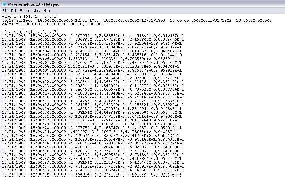
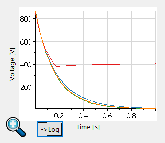
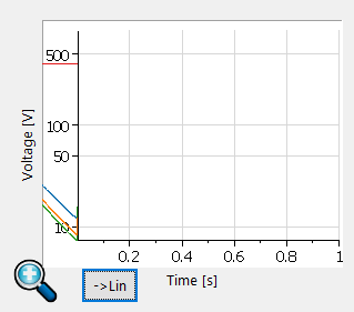
Inconsistent behavior of the object Curve2DPreview with YAxisScalingType
I'm trying to draw some curves tiara with VBScript. The only tool I found is the subject of "Curve2DPreview".
The curves are an exponential decay of voltage. When indicated on a linear scale, they look like this:
I put a button next to the plot to change the logarithmic scale, and when I do the result is the following:
Someone knows how to solve this problem and intrigue in the right position?
More information: I have DIAdem2015, the four curves are curves of waveform.
Thank you
Hi franco__,
You're right, that's not correct. The only workaround is to convert the string of waveform in an X / Y pair of channel and display this. I hope that we can fix the problem for the next version of DIAdem.
Greetings
Walter
Maybe you are looking for
-
Click right button does not not on Satellite P300 - 19 p
Hello Monday, I bought a Toshiba Satellite P300 - 19 p.And I love it! : ^ 0 * Only today I turn it on and my right click button does not work! :-(I would appreciate any help that can get the button works again before I decide to drive to the store wi
-
I have an iMac 21.5 "2009 end which I never had no problem with. It is Yosemite 10.10.5 running and after a recent software update has become very unstable. After I restarted recently he crashed 5 times a day. It seems to be the internet causing the
-
OfficeJet 4620: HP4620 responds to all calls in automatic mode
Apparently I never understood what the auto answer for the fax machine. I had always had put auto answer until recently when calls non-Fax began to be answered by the fax machine. There is a telephone and answering machine sharing the same line with
-
Update FAIL! Windows Server 2008
Hi all for some unknown reason, I am unable to install "Windows6. 0-KB2117917-french-x 64.msu. I get the same error: 0 x 80070020 normally, I don't like, but since I tried to install this update I lost the ability to view/edit my server with this err
-
I have several old Compaq Presario SR1563CL which has a completely updated Windows XP, Norton AV and other software a year. Today, a blitz of spam by pretending to be shipping notice hit my email AOL Time Warner Cable account. The only damage is that