Read the VISA of RS - 232 on cRIO-9012
Hi all
I'm reading a GPS signal via port RS-232 on a cRIO-9012. I enclose the simplified code.
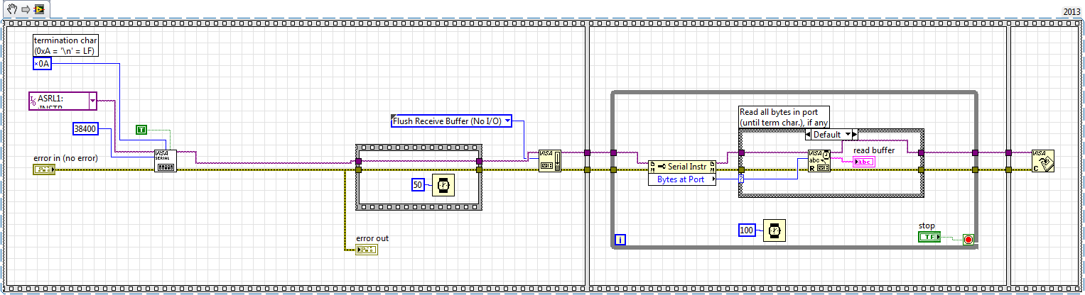
The same code works when I run it on my PC (after changing the port) and transmit the GPS signal via a USB port using a series converter / USB. However, when I plug it into the port RS-232 on the cRIO and run it on my cRIO, the buffer seems to be in the wrong format, i.e. some information is read, but it shows some weired characters. Does anyone have an idea on how to fix this?
Thank you
It seemed that it was a hardware problem. The cRIO-9012 was probably too old/weak/slow to handle communications. Passed to 9022 and it works!
Tags: NI Software
Similar Questions
-
How to read the host name or serial number cRIO locally
I have not worked with cRIO and decided to ask for help. (o).
I don't know about the screws that allow to access this information from a connected Windows machine, however, I want to retrieve and display this information on remote panels. But I cannot determine how to read the cRIO hostname or the serial number of the software running on the cRIO?
Thanks for the help.
James
This could help.
-
Data drops using reading series visa
I'm having a problem using reading series visa when you transfer a picture from one PC to another. Writing PC transfers data systematically as seen by the probe on the chain get into writing. Exe read the string displays however the string table once and then on the next reading displays an empty string. It seems new and fourth without a complete data string and an empty string. The vi that data comes displays a table updated consistent but the exe read the matrix (via RS 232) switches the vacuum to the full establishment of the loop rate which is fixed at 1 Hz.
Teslac wrote:
files/NOR/Labview e (toward) Progam vi.llb\Advanced String? Well Yes
Bravo and thank you. There are buttons for those
 Bravo - simply click on the star under my avatar and brand the solution - (Options > OO > on your right, at the top of each post "Accept as Solution")
There are three reasons for this:
- Other contributors know that they can focus on helping out elsewhere
- It is easier to find the next person with a simillar problem
- We LOVE 'Solutions-pronounced ".
-
Can I use SMB connector in cRIO 9012 as an external trigger source to excite my system?
I use the clock real time of a cRIO 9012 for generate two pulses with a deadline given to fly a lock-in amplifier. Unfortunately, the jitter generates a beat that gets worse the ratio of SN. I would like to use an external source to trigger the system and reduce the jitter. Can I use SMB connector for this?
Hello
What color is the status light? It is green or amber? According to the manual, a solid status light means the cRIO met a fatal error, which could mean a lot of different things. After you reformatted, you redeploy the code that started this issue? If so, I would try again and do fitness then deploy your exe to boot. In addition, you might want to try to restart the cRIO with the no app switch flipped on the position 'on' and see what happens.
Another good troubleshooting step is to get information via the serial port. Here are instructions for how to do this. If you attach this information to this topic, I can take a look.
Thank you
-
How to read the status of User1 DIP-switch with a cRIO FPGA chassis?
How to read the State of the DIP switches on a FPGA cRio chassis?
I work with a cRIO 9022... My idea is to put the system in "service" mode with USER1 switch to IT and communicate with the FPGA via the FPGA - GUI (VI) on the host computer instead via the RT module that is used in normal conditions.
Any ideas? Unfortunately, I don't have an unused channel on the left... .and (as I know) cannot use the interface RS232 of FPGA.
Many thanks in advance,
Luke
Hi, this is the correct information. You cannot read the FPGA of DIP-switch status. The only thing you could do is to use the function of Reading Switch.vi located under the range of functions-> real-> utilities RT time
It's how you probably know side host RT and not the FPGA.
Cordially Virginia
-
How to read the Serial Arduino data using labview VISA?
Hi =). Im a beginner work reading data series from an arduino but im facing... Lets do it step by step
I built a voltage divider circuit which gives from output
from 0 to 5V. The output of this circuit is sent to a 0 analog input pin
of a Committee of Arduino Duemilanove.(1) Firstly, I connected the cable to connect to my laptop USB the Arduino.
(2) I went to start-> control
Control Panel-> system-> hardware-> Device Manager. Check the Ports (COM
& LPT). In my laptop I can see USB Serial Port (COM4). Now I know only in
LabVIEW that I must read the data series COM 4.(3) to the side of the arduino, here's the code to read changes in voltage
entered to analog pin 0. The last line of 'delay' determines the sampling
Rate of how we want to taste the output of the voltage divider:int potPin = 0; Select the input pin for the output of the voltage divider
int val = 0; variable to store the value from the probevoid setup()
{
Serial.begin(9600) (9600); Opens the serial port, establishes the rate of 9600 bps data
}void loop() {}
Val = analogRead (potPin); read the value of the voltage divider
Serial.println (Val);
Delay (10);
}I slightly modified the basis series reading writing VI... I have
attached the block schema used with comments. Basically, I tried to read
data series, divide by 1023 and multiply by 5 to graphic voltage
variations of the voltage divider circuit. But Im not getting
the correct voltage output values. The value of the tension just keeps go
0 and coming again, as shown in the photo.Could you guys please guide me on what went wrong?
Thank you!
-you read the data, even if there is no data on the port. If 0 bytes are read => «»
-in the case of false, you resources VISA wired for the output of channel tunnel?
-There is no close VISA at the end of the VI resources
-you're not a loop this VI reading bytes
I added an addaption of your VI that you should give a try maybe
-
Stop the VISA to send automatically the characters of endpoints on read
Is there a way to stop the VISA to send characters to the endpoint on read? The instrument that I'm trying to contact (Olympus IX-81) requires 2 of them and it seems to be quite the hassle to implement both in a single command. I think it would be easier to write just manually with every order.
Please do what I asked you to do in your other thread. Simply right-click on the control of the chain and it is said Normal display-display or display Hex Codes. Place a probe on the string to write VISA entry and indicate exactly what the probe has. You have the instrument and the code and here is the troubleshooting steps based. You can also turn the tracing OR in MAX and set track or report what he said. You said that he worked with MAX so a comparison with the string sent there and what the VI sends is an important step to isolate the problem.
-
problem with the bytes to port to read in VISA
Hi guys,.
I'm reading device data using usb - BT dongle. It creates the virtual port and read without problem.
My problem is the packages to send 428 bytes, inside this block device, I have 400 bytes of data bytes 9 to 409. The first 3 bytes of each block is the same.
4 45 50 - MEP, they are the first 3 bytes of each block of 428 bytes.
Okay, if you check the vi I config the visa and sending the data of adjustment of the device, read the answer and it sends the data to start sendding data.
Well, I try to read each block of 428 and show in a chart.
The problem is sometimes bytes in ports are 428 and anothers shows 23, 2, 125,... is not continuous 428 bytes each iteration and destroy the data graphic.
IF I check the chart outside of the main loop, I see the correct graph. Apart from mainvi I collect whole data and separate in 428 blocks, extract the 400 bytes of data and analyze the entire signed 16 bit and display in the graphics.
So, I don't know the best way to get 428 bytes in each iteration... I tried to read directly the 428 bytes but sometimes fail once again, very low reading bytes... take time to wait before read bytes to each iteration. I need a way to get 428 before values to get the readings of 400 data. Even I could probe each beginning of block with 4 D 4550 HEX bytes to pass and got data...
Perhaps it would be better to use the wait? or using a while loop to wait until I had 428 bytes? Any help will be apprecite.
Best regards, Fred.
You receive binary data. Therefore, turn off the the stop character.
What happens is that you actually 0x0D in your data. Playback VISA who sees and then request's made it reading the data. By turning it off, then reading VISA will read all 428 bytes or until a time-out occurs.
Let the constant instead of the bytes to the Port.
-
Error reading the attached viSA-1073807339 using Subvi, but why?
Hello
First of all, thanks to all who respond!
I read N9020A Agilent MXA Signal Analyzer data. It is successful if a Subvi is used to playback VISA; otherwise "Read Error-1073807339 VISA' rears its ugly little head.» The Agilent gives the message "REQUEST not COMPLETED" just as endearing.
The on error-1073807339 OR Knowledge Base article talks about the need to put an end to the chain of command correctly and explains how to check it by double-clicking the control of chain of command on the front and changing the display of '-' Display Mode of the Codes. I call the VISA Read VI in the block diagram; It does not have a chain of command of front panel control, so I don't know how to apply these tips.
In any event using a Subvi to perform the Read VISA takes care of the problem, but I have no idea why. The VI image that does not work is "Agilent MXA Sig Gen vi.png." A big thank you to Mike on the Agilent forum which provided workaround.
Nina
Mark, Fan of the crows and any other interested person:
I found the error in Agilent MXA GIS Gen.vi. There is typo in one of the VISA WRITE commands. Originally, it was
: MMEMORY
 ATA:? "D:\TEST. PNG"
It should be
: MMEMORY
ATA? "D:\TEST. PNG' (remove: before?)Your comments have been invaluable. Thanks a lot for your help and your patience!
Nina
-
The value read by visa read that VI is not correct!
I design a labview program to control the Agilent E5072C Network Analyzer. When I want to get the value of this instrument, I use VI "VISA read" listed in the plate. However, the value read from this VI's latest measurement of time value. For example, the last time that the read value is 1.0 db, and this time the measurement value is 1.2 db. But when I use 'VISA read' VI to extract the value is 1.0 db.
Agilent also provide a VI for this device to read the measurement value and she was always correct value. If someone could tell me why? need to do any action before the value read from this instrument if I want to use VI "VISA reading" instead of Agilent VI?
You are probably reading too quickly. Reading it in NOR-MAX, you do it by hand, it takes more time. When you do that programmatically, it is "instant". Try using the * OPC? command to activate your order in a query. He returned then a '1' in the buffer. Read the '1' and then create the command fetch.
For Dennis:
I've had bad experiences with the drivers provided by the manufacturer to the point where I don't even try to use more. But Agilent is also anal about their drivers, because they are on their books, they should pose no problems.
-
reading the name defined in max or resources visa
I have change the name of my visa OR max resources and I really want to save these names as group name in a PDM file
I could find name inst intf
Thank you very much for your help
concerning
Pascal
Hello, PBAN,.
You can use the configuration API of the system OR of y to achieve:
https://decibel.NI.com/content/docs/doc-13216
Using this API, you can easily create examples such as the attachment.
But there is much more to this API, then just this example (or rename aliases).
The NOR example Finder should provide you with enough examples.The attached Code is provided as is. It has not been tested or validated as a product for use in a deployed application or system, or for use in dangerous environments. You assume all risk for use of the Code and the use of the Code is subject to the license terms of Sample Code which can be found at:
http://NI.com/samplecodelicense
Alternatively, you can also read the alias of your hard drive ini file and modify it programmatically:
http://digital.NI.com/public.nsf/allkb/F02B2BF8943A31D786257393005D16F1
If you plan to use the second approach, then copy the configuration file screw that allows to read/write .ini files and default abailable in LabVIEW.
-
How to run vi continuous when the VISA read timeout happens
Hello
I'm using LabView 2010 through a series of Agilent 6000 Oscilloscope. The Oscilloscope reads data from another experimental machine which will occasionally fail due to failure of the sample. When the machine breaks down, it ceases to send signals to the oscilloscope and leads to the error timeout of read VISA and the vi It is over. Is it possible that I can run the vi permanently when the error occurs? For example, when the error occurs, it stores the error in the thread of the error. When the vi read the error code of the wire, it sends a command to stop my experimental machine then stop the vi.
So far, it stops simply during the execution of the visa, playback function. In that case, why do we mistake in and out? Vi stop just when the error occurs.
Thank you
Laurent
-
urgent request: how to read the value of a register using VISA read?
Hello world
This is a very urgent investigation. can someone help me please? Thank you very much!!
I wrote a few commands in several registers using VISA write. now, I want to read the value of a different register.
But the bytes returned are just the commands, I wrote before and a few other commands that I don't know what they are for.
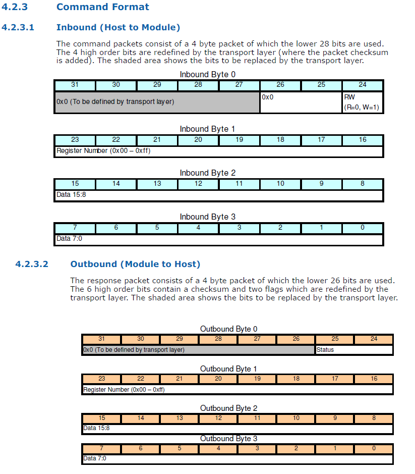
This is the format of the command, and I enclose the sheet... I want to read the value of register (0 * 41)
.
Ravens, if you have something more than me, do not so much it at all =)
The command you have posted has several components:
The gray area of the transport layer uses for a checksum
several bits set to 0.
a single bit to define if it's a read/write operation
a byte to identify the register of interests.
two bytes for the data.
With what you have provided, there are only three things we need to worry:
(1) set the R/W bit to 0 to mean we're reading rather than write.
(2) set the second byte 0 x 41 to focus on the register of interests.
(3) with a reading, I can't imagine the last issue of two bytes. They probably ignored. The documentation you provided does nothing to explain this. The most logical thing I can think is that these two bits contain the data, you go to the registry if you set the R/W bit to 1.
There are two parts to this communication. The first part is an entry VISA to send this control unit. It is likely that you will need to complete the message. You will need to know how to do this.
The device must respond with the message that you mentioned in the original post. Crows is right. He's coming back as a string. You can use the subset of string to separate the components defined by the standard. You can use these components to determine if the data is legitimate and then do what you want with the data.
-
The VISA read function is not read the bytes specified in the buffer zone
I created a program that continuously acquire data of the inverter. But, the "Reading of VISA" function is not rreading all bytes of the buffer, which is a big problem because the way my work programme is it will extract the specific buffer bytes and convert these values in voltage and current values.
I specified the number of bytes that I want to read the buffer as for example I want to read 21 bytes. But, even if there are 21 bytes in the buffer, the read function VISA read only 9 bytes. Im not using any character of endpoints so this is weird. I'm using LabVIEW 2011.
Is attached a photo of my program and the results.
You still have the active stop character. You must connect up to a FAKE at the entrance of termination character activate on the Serial Port to set it up.
-
Basic visa write and read the example
I use basic visa read and write example to control my temperature controller in fact it works perfectly, but I want something else. First of all, I like to read the value of continuous temperature and it can be read on the read string section but I want to do but digital indicator to see the temperature value is it possible? And what is the function I should use for this? In fact I used the analysis of chain to do but I have not checked but it works or not?
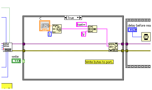
Second, I have to set temperature sometimes on the controller actually I can do writing tset = 025,0 to set the temperature F 25, it works when I write this command in the Panel (string to write), but I want to do like DIGITAL controller or something like that instead of writing the command for each setting is possible. I want to increase or decrease the temperature by pushing the increase or decrease button instead of write tset = 0.250 / a. could you help me with this?
Thirdly, I want to run some parts of the program permanently a part when I want to run, as possible, now I have while loop and my example works permanently. I want because when I set the temperature which must not operate continuously, because it is a time command to read the temperature value this section runs continuously as the temperature on the experimental set-up is changing one I have to see this change, for example I set temperature 100 F and the peripheral controller 100 F heat , but this order is an order of time, but read temperature command should run continuously because the temperature is changing and I need to read the temperature for every 60 seconds and I can be a part.
Make sure that you concatenate text constants "code view".
Maybe you are looking for
-
I'm on El Capitan, and I am not able to send e-mail
I am unable to email sent from my mac. He wants to know my password, I changed from verizon, and my mac says that he cannot verify
-
the iPhone 5 and other battery
Last December (2015) I had my battery replaced on my iPhone 5. About two weeks later I had to have the battery replaced as it was a defective battery. After that, everything is like new. Last Saturday, my sat phone to 100% every day even with constan
-
UltraBay HD missing in wake up with Windows 10, T530
Hello Since I changed to Windows 10 (new installation), sometimes the HARD drive in the Ultrabay slot gets detached after wake up from sleep. First of all, I can hear it lights, then it turns off and a notice told me that the HARD drive has been remo
-
DIFFICULTY zoom mode Prototype - add in the zoom tool
HelloAs much as I love XD and don't mind the switch between mode creation of prototyping , useful and used tools like the zoom must be more prototyping modeIts a complete question UX is not not able to zoom accurately in prototyping mode. You are oft
-
Why can't scan to PDF with acrobat reader dc
I've recently updated to Adobe Reader and can no longer scan documents to pdf format. I can scan tif or jpeg not a pdf file. I heard that I have to buy something from Adobe that will allow this function. Is this true?