Recognition of map to play using LabVIEW and a webcam
Hello
For our project in my school (2nd year of electronic engineering), we are a distributor of Blackjack robot. In the help of LabVIEW and a webcam we'd like to take a picture of the card he's going to face and then compare it to a database, we did prior to that the program knows which card it is.
So what we really want to do is
-scan the card he'll deal with (take a photo of him)
-compare with our database of predefined photos of all playing cards
-Once it has good info is obtained, channeling through our program so that we can count and whatnot with this card.
-He needs to recognize the value of the card, not the type (i.e. must know that it is a 4, not that it is a 4 diamond)
I have not found a good solution, again, can someone help us project? Any tips are appreciated with kindness
Kind regards
Vincent
Tags: NI Software
Similar Questions
-
Time real ADC/DAC for SMPS by using Labview and USB
Hi all
I asked the Sales Department of this same question, so here's a two-pronged approach:
I am reserching a control algorithm for power switching, and so far, its performance simulations seem to be good. Now, the goal is to implement the circuit from the experimental data.
I've seen several NI USB DAQ boxes that seem to have the performance, I'm looking for (for example, the box USB-6211 a sampling rate and resolution I need).
The control algorithm uses the following mathematical functions: add/sub/mult/div/exhibitor and derivative/integral.
My question is this: is "strong enough" Labview take four-channel data 250Ksps, crunches the numbers in an equation and spits out the answer to an analogue on the channel, while time REAL? I'm looking for a rate of analog output of ~ 100 kHz.
Thank you for any suggestions you have!
-Rick
Hey,.
So if you were trying just to perform an input or output, then the box USB-6211 would certainly be able to treat it as the machine clock could manage the inputs/outputs, no software. However, what you are wanting to do, basically a feedback system, he will have to avoid (at least to a USB device) because you need to be able to specify Active which is the output. So, for this reason alone and the fact that you want out of 100 kHz, this device and the USB devices in general will be not an option any what software you use, LabVIEW or otherwise. On another note, you want to make sounds more like live update, not in real time, which is more on the jitter. Bottom line, for these kinds of requirements, you might need to move to an FPGA card, something like the NI PCIe-7841R would work. It's more expensive, but for your needs, FPGA will be the only option and it comes down to the latency of the bus, but also the response time of software. With FPGA, as shown in the first scheme of the following document, you basically close your software through hardware loop.
Basics of FPGA
http://www.NI.com/white-paper/6983/en
-Ryan S.
-
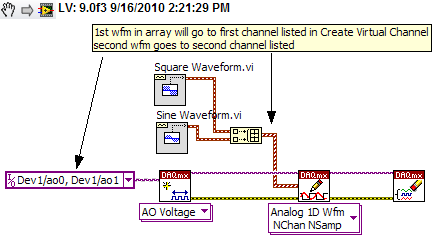
Using Labview and PXI-4461, how can I AO0 output Signal Square and AO1 output waveform
I am using PXI-4461 and Labview, boredom, generating 2 signals simultaneously.
How can I get AO0 out square and exit AO1 SignWave?
Help, please. (The example Code would be nice)
Thank you.
Create two signals and make a table with them. Use DAQmx Create Virtual Channel to create two channels. First waveform will be sent to the first string, second waveform on the second channel.
I understand not all as calendar, clock frequency, amplitude, trigger and other parameters. You can add these things. This is just a basic example.
-
Choose and place using labview and or vision acquisition
Hello world
I'm doing a project studying on Vision guided pick and place of a robot (abb) industrial. I would like to know the steps involved in the creation of the block.
I locate the object, move his webcam cooordinates. Then made a pattern match, and would send the cooordinates to the microcontroller. then from microcontroller for control of robot... then the industrial robot should choose the object and place it in a predefined area...
I would be extremely grateful if you guys can help me because I am new to LabView.
Thank you
Pradeep.M
What you describe is quite complex, but here are a few tips. The key is to establish a correlation between the coordinate system of the robot to the coordinate system of the camera. I guess that the camera is statically located above the pick-up area? I move the robot at each corner of the frame to its choice position vertically and note the position of the robot at these locations. These 4 points in space will be correlated to X, coordinates of pixels in the camera image. Basically, you need to write a sub - VI with entries being pixel X and is coordinated and coordinates output being the robot.
Writing a test application saying the robot to get pixel location to any X, Y in the framework to test your Subvi. If this does not work, then you need to set up a correspondence to the model. You probably want to do a geometric pattern match. Take a look at this example: http://zone.ni.com/devzone/cda/epd/p/id/5555
You will need your pattern match algorithm to return both the coordinates for your robot, and the orientation of the tool needed for good pick up the object (if the pick-and-place robot tool requires to be in a specific direction). If it's basically up to you will convert the object X, Y and rotation angle in the framework that you receive correspondence from model to any coordinate system, the robot uses.
The placement algorithm could be simply an adjustment of orientation to the object being investment and then investment positions could be an array of coordinates of robot which you browse after each pick.
Be sure to implement security mechanisms in your algorithms so that the robot can never go somewhere outside of a safe range of coordinates.
-
Using LabVIEW and LabVIEW 7.1 2010 on the same PC (Windows XP)
I have LabVIEW 7.1 on a Windows XP 32-bit PC, and we intend to move to LabVIEW 2010 soon. Many of our software uses traditional DAQ, DAQmx and DeviceNet. We have to use both versions of LabVIEW for awhile on the same PC. Is this possible at all?
I installed a trial version of 2010 and now I don't have DAQ and DeviceNet in LabVIEW 7.1. Any suggestions will be very useful.
Thank you, Nick
See this recent thread:
http://forums.NI.com/T5/LabVIEW/DAQmx-version-for-LV-8-2-1-and-2010/TD-p/1276594
Then maybe you can use different boot partitions or virtual machines.
Felix
-
Problem using labview and GPIB
Hi guys,.
Finally got recognized my tool GPIB in labview, which is nice. I created the block (attached you can see you diagram) but it works like 20 sec. I press run continious and I can change the values in direct mode, as I hear it. But then after 10 seconds, it appears the error that is in the screen and only works again if I reboot the function generator.
The model is Tektronix AFG3102.
Concerning
-
I have loaded SKPE on my computer a few days ago and it worked fine, now I can't connect to SKYPE video. The error message is that the webcam is not detected. An additional message, is that my computer is slow. Can someone help me?
Hi timmsmichael,
Try the steps mentioned in the sub link of the Skype community and check if it works
http://Forum.Skype.com/lofiversion/index.php/t95046.htmlAlso check if all parameters of video call in Skype are positioned using the link below
http://www.Skype.com/intl/en/allfeatures/webcams/For additional support post your query in the forums of Skype.
http://Forum.Skype.com/I hope this helps!
Halima S - Microsoft technical support.
Visit our Microsoft answers feedback Forum and let us know what you think. -
We are about to upgrade to VIsta using LabVIEW and I'm sure that a lot of people out there have experience with this.
Y ' All could let me know or give links to:
-What need whatch out for
-Learn about the issues
-Availiblity pilot
-No problem with older versions of LabVIEW with Vista
-Anything else I might need to know.
Thank you
Joe v
Hello
For more information on the older versions of our MS Vista compatible software and drivers, please visit the link below.
http://zone.NI.com/DevZone/CDA/tut/p/ID/6893
Please let us know if you have any other questions!
Anna Kozminski
Technical sales engineer
National Instruments
-
help the guitar hero automated using labview
Hi, Im working on my final project for a class e and Im making a guitar hero automated using labVIEW and vision builder. I already have all the buttons and the strum bar, but I need help with the whammy bar. My problem is that it should only work on the notes which take more time with a single click, I think I should add some time delay (or something like that) so if the camera sees the note more times the amount of time its will send a signal to the solenoid to continue to press the whammy in intermittent form bar (I think I need a square to wave this) part).
I'd really appreciate if someone can help me or show me an example implementation of the part.
Here is a video of a similar project without the whammy bar
Edit: Im using a NOR-cDAQ 9472 module for output on a digital OR cDAQ 9171 chasis USB
Thank you
Javier Morales
Dear Javier,
It sounds like a cool project work.
Why not try wiring of the output of the shared in a shift register variable to retain the previous values and compare the old with the new value using a door and. You can connect to a wait function in your loop and wire abour 100ms, normal human reaction time, while is the button held for two cycles this triggers your whammy bar.
I hope this helps.
Kind regards
-
Hello
I have to synchronize two software to 20 ms of precision, the timestamp of labview first single use (128bits, 1904 ect...) and cannot be changed.
and the second is written in C++ using DAQmx, I find the trick of subtracting the number of seconds of a struct tm classic.
But it's not accurate enough for me.
The only solution I found, is to use Structure SYSTEMTIME and use the same round as the struct tm.
But I do find it very nice, so is it possible to use the same routine as labview in a classic C++ program (or cvi classic)?
Thanks in advance!
Eric
Hey Eric-
I don't know if you are still working on it, but I thought I would mention the time CVI API absolute in the library of utilities. It uses the Format binary time of National Instruments, which I think is what should use LabVIEW and should meet your needs.
NickB
National Instruments
-
How to interface a simple way using LabVIEW 2009 simulink model and SIT?
Hello
I finally found a way to use a template simulink with LabVIEW and the Toolbox to SIT, but I'm not satisfied.
If you have any suggestions, the link of resource that I missed, please do not hesitate to answer
Note that I do not know much about simulink, so that is my question seems stupid, let me know what

Software configuration
OS: Windows (not an RT target)
LabVIEW 2009
SIT 2009
question 1: interfacing the model DLL (mapping considerations) with a driver VI
We have created a model of DLL by using the 'Workshop in real time' tab in simulink.
In LabVIEW, launch us the tool 'SIT connection manager' and try to use the DLL with a driver VI by mapping the e/s model for screw/lights orders.
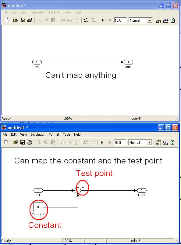
The fact is that I fail to connect to my controls/indicators VI/o model because they do not appear in the mapping dialog box.
The simulink single objects that I managed to map are "constant" and "test points" while I need to edit the template simulink itself (example below)
Are in e/s model, not considered as part of the parameters of the model? (this could make sense because the mapping says in fact that it operates on "model parameters")
Is it possible to link the IO model VI commands/lights?
Note:
-the "configure HW i/o mapping" dialog box allows me to map model e/s with e/s HW...
-The examples also use these "constant" and "test points".
2nd question: use of direct screw SIT
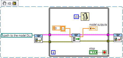
I tried to use the DLL directly with the screws SIT (code example below)
This kind of code works well on another project (target of 8.0/RT LV) but not on the current project (LV 2009/Windows)
The second stage of the model never ends:
-0-index of the loop works as expected (model doing its job).
-index of the loop 1 starts normally, but execution is stuck in the 'SIT scheduler.vi.
Then I have no choice that to kill LabVIEW ("Reset screws" windows appear if I try to stop/close them).
Is there a reason that I do not see what explains this behavior?
Thanks for reading.
Any help appreciated.
Kind regards
Hello
I spent some time analyzing the VI driver as you suggested.
Here are my findings.
Question 1: the SIT connection manager does not pass to the model SW controls/indicators. Only, it allows the user map HW AIs/AOs.
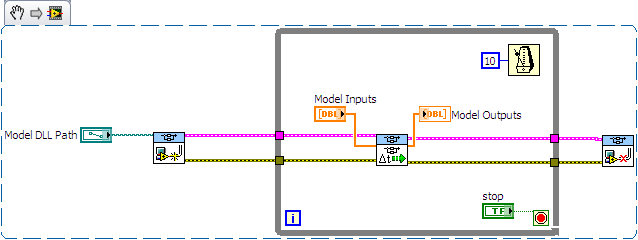
The only solution I found (to have a SW - for example a shared variable - object that is mapped to an input/output model) is to customize the VI driver that is scripted by the SIT Connection Manager ("_Base
rate Loop.vi" in the flat sequence structure named "read code") Question 2: after spending some time in the VI driver, it seems that the VI to call right is not 'SIT scheduler.vi' but 'If SIT take model no time' (which uses the other as a Subvi)
My conclusions are correct? If I use the API in the wrong way, please let me know.
Kind regards
-
speech recognition of labview and Arduino
Hello
I want speech recognition with Labview and Arduino. I have already install driver of Arduino and test it in Labview. I want to ask if it is possible to guide me if I want to use hidden Markov and algorithm of ANN, what should I do. In fact, this project is belongs to the robot by voice control, but my knowledge of labview is not so.
Hello Mohammed,.
Are you familiar with the theories behing Hidden Markov Models?
A good starting point would be, for example, this document:
http://sites.stat.PSU.edu/~Jiali/course/stat597e/Notes2/Hmm.PDF
-
I want to buy an iPad 2 Air and run Hema maps on it - Hema Explorer and 4WD Hema maps. Can I run these on the iPad 2 to Air EVERYWHERE in Australia because it indicates that the iPAD has 'Assisted GPS and GLONASS' or do I need a SIM card as well. I want to use it for travel in the outback.
Only if they are available in the iTunes App Store.
-
Apple TV 4 will not play my movies that I had in itunes. It says unplayable format, but it is the same format that I use always and a lot of movies? What could this be?
This new IOS is bug.
I had the same error message and tried to "create a different version" in Itunes.
The ITunes says "this video is already formatted correctly."
I tried to play again on the Apple TV and it worked then after a bit of buffering.
-
Using the Manager of synchronization for exe OI LabVIEW and TestStand
We would like our operator LabVIEW executable Interface send data via a queue of TestStand to a sequence of logging. The SyncManager API looks like a slick way to do this because it allows access to the synchronization objects other processes outside TestStand TS. I created an experimental sequence of trying the concept. The sequence creates a queue with a step of queue TestStand, up a point to another TS not queue, then uses calls to ActiveX in the SyncManager API to add another element to the queue of waiting. That all works.
When I added a LabVIEW VI to place another element through similar calls to ActiveX in the SyncManager API, the VI is not a valid reference to the queue and so it cannot place the element.
I read on the forum that TS queue name must start with * in order to be accessed by separate processes on the same computer. When I add a * on my queue name, queue TS operations continue to operate, but step that uses a call of ActiveX in the SyncManager API to get a reference to the queue returns one null ref so the next step of enqueue ActiveX returns an error. In addition, the LabVIEW VI still does not receive a valid reference to the queue either.
Ideas and suggestions welcome! The sequence and LabVIEW VI are attached. Using LV and TS 2012, obtained similar results in 2013SP1.
Thank you!
HansThe queue API expects a PropertyObject not a string for the newElementPropObj parameter (not sure why LabVIEW similarly let you thread a string). To create a new PropertyObject, you can do something similar to the following:
myProperty = engine. NewPropertyObject (PropValType_String, false, "", 0);
myProperty.SetValString ("", 0, theActualString);
Enqueue it.
Close the ref to myProperty after you're done with it (i.e. after the queue it) in order to avoid leaking.
-Doug
Maybe you are looking for
-
HII... I'm using Apple Tv 4th gen. Menu button and Home does not respond even after a reboot by pressing both button. Any idea?
-
No power on refurbished Satellite L350-14F
HelloI recently bought a refurbished L350-14F to a company eBay (http://www.clearancebargains.co.uk/). It arrived today and after plugging in it, there is no power to the laptop, no indicator of system or anything like that. I plugged the power cord
-
Is it possible to have my iPhone 6 and Apple Watch both make a noise when it receives notifications?
I have look under each setting and can't find anything. I work in an environment where the sound of watches is not quite enough to be heard, but my phone can be. Yes, I have a set of haptic at max too, but I want my phone to ring for notifications as
-
In Windows XP, when burning data on a CD-ROM, is data memory buffer or soft file burning as well or is it an authentic copy of the end of the file?
-
I use the LifeChat LX-3000 USB for my Skype calls on a Dell Vostro 1510, is there a way I can get the headphones pluged in uninhibited my computer speakers? Thank you