Rectifier of waveform or thresholding to form VL
Hi all
I just started using Labview so please bear with me.
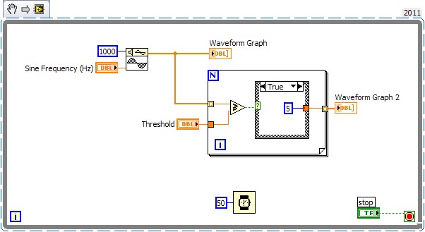
I want to convert a waveform generated from an entry in an equivalent digital/square wave with only two values of Y by defining an analog threshold value. I was trying to index in the table of the original waveform of the values Y and check this value compared to the threshold value. If the value is less than the threshold value and then change the 0 value to a constant value of constantly changing otherwise.
I struggled to generate square wave form I was looking for.
I'm not sure what a loop to use (while, for, or nested). I have a while loop on the spot because I expect a continuous stream of analog input data to convert.
Is there a similar vi there that I could mention?
Thank you!
He would do something like this:
Tags: NI Software
Similar Questions
-
How to get the length of a waveform above a certain threshold?
A simple problem... I have acquire the data of the DAQ Assistant and read it back draw the measures file using read.
My signal will be with just a peak (see figure)
I need to find the duration for which my wave form value is more than 150.
I am unable to find that the waveform of time first crosses threshold... but the second point waveform the threshold comes in... I'm not able to find
second attachment is part of the created vi...
If I can find the second time where the wave goes the threshold, I can calculate the time using dt...
As David and VSH have hinted at, you can use threshold spikes. I did it several times... See the attached VI.
-
Number of averages for time waveform acquisition
Hello
It is on the configuration of the device - settings of the acquisition.
in the parameters of the collection file, can I know is there a way to feed the number of averages and % of overlap between averages aquire waving time.
Thank you!!
BR
Pattabi
In version 3.0 of InsightCM, we will support an average and overlap on the data of the spectrum Viewer. These settings will be applied only to the visualization of the spectral data and will not apply to calculations on the waveform or spectral data form.
This will meet your needs? Or are you interested in doing an average and are superimposed on the spectral data to then be used for calculations that are based on spectral data - such as 1 x Magnitude, etc.. ?
Thanks for the question.
-alan
-
Sorry to bother you guys but apparently I'm not grasp an important point with the live paint and live paint groups.
I did an Illustration, everything is as I want it. I take the selection tool and surround the illus with a rectangle encompassing. Good to go far... then so I'm going to object > live paint > make. Up is my live paint group. I choose a Coilor of filling and a color contour, and when I click on the artboard is only updated with the fill color in some areas of your artwork. NOTHING to do with the paint bucket or the live paint Selection tool will fill the other news of the illustration. I developed the LPGroup and AGAIN, it won't let me put the color, I used the LP selection tool and it will not activate the areas that I couldn't paint with the LPBucket.
Can someone give me an idea of what I'm doing wrong?
Thank you in advance for any help you can give me.
JJ
Other objects form logic cantonments, fall outside the gap detection threshold or forms have been built using combinations of transparent traces with clipping paths that are not eligible for the treatment... Make a choice, but without seeing the shape you will probably get more conclusive step answer that...
Mylenium
-
Realization of comparator: constant double input signal - waveform, threshold.
Hello
How achieve the comparator, where the input signal's waveform type (from data acquisition) and the threshold is a double constant.
These two types are incompatible, then a conversion must be made. Which one?
Thank you
Pavel
-
Hello
I am teaching LabVIEW. I want to delay a wave form and display it with the no delayed waveform. I used a delay in the examples. The output of the delay is thread (double waveform). Signal to simulate output is data Dynamics. My conversion of the thread (double waveform) Dynamics does not appear on the graph of a waveform. The VI is attached. Can anyone offer any comment.
It's displaying fine. The screen is hidden behind the screen of the second signal. Expand the Plot legend to display all three plots. Then toggle the visible property of the plot of the second and third plots.
Lynn
-
I would like the Waveform generated with the signal generator to wait until the user presses a button to start. I tried this implementation with a structure of the case, but have failed. The problem is that I don't know what to make out of case for when the user has not yet pressed the button.
Consider using the structure of the event instead of the structure of the case. So pass the generator of waveform in the structure of the event, so that it will be executed when an event like the mouse click occurs. http://zone.NI.com/reference/en-XX/help/371361J-01/Glang/event_structure/
-
First of all, please forgive my ignorance. I'm new to labview.
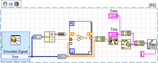
I would like to create a .csv (or any other excel document) file with the user input (time, title of Test, operator and test sample) at the top of a spreadsheet, and then the signal chart data in the same sheet.
You must save the png on your pc, then do it at your block diagram.
As the waveform is periodic, you just have the t0 and dt, but if you want to assign all the points that have been recorded, you can try something like that.
-
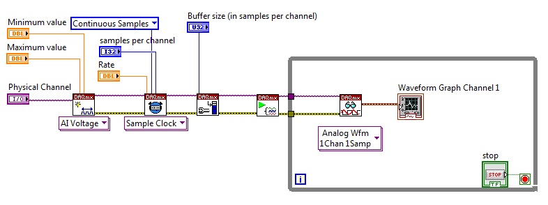
Acquisition of data above threshold
Hello
I started with LabVIEW, a few days ago and found it quite difficult. Hope you can help me a bit.
My task is: 2 channels (from acoustic sensors), I need to find the time of delay of arrival between them and then to calculate the coordinates of a source that emits sound waves. Then, I looked at several examples that I could find and finally I am stuck at the very beginning.
I need to work with signals (impulses) are greater than a certain threshold, but how can I do this? I do use the Detector.vi threshold or not?
Then I need to find the delay of arrival time. Use CrossCorrelation.vi?
Thank you very much.
OK, the data type of waveform coming from reading your original image is just the default output. You can also acquire the three channels in a single acquisition job by specifying several physical channels and change the output in a 2D DBL table format. In this form, the columns are different channels in your task of CQI. You can then treat each channel I described.
Mike...
-
Is there a way to bring back the audio wave in first CC original-form because it is not readable?
There is a checkbox indicating signals display rectified, this must be turned off. I'm not at my PC at the moment and I can't remember where it is. Try to do a search of forum of rectified waveform.
-
I applied a form of tile to a clip in the Locket, but form controls are not appearing in the Inspector. The Help menu says they should be under the threshold of effects. I want to soften the edges and may access other controls, thx.

This is the help page describing the shape masks. By clicking on the order indicated by the blue arrow evokes generators, but no form of mask. I used the tile, but cannot access it again, and that we can soften the edges with?

.. .and there's a list of form controls and he disappeared for help. (no support!) .. .but what is the command to raise? As you can see he was there before, and now it is not.
I would like to meet the sadist who wrote the Help menu and tell him how much of my precious time, it is lost... and that's just for starters
PPut the pointer over the bar that shows the effects to display the button display. Click on it to open the Efeccts commands.
-
Script for random switch between different waveforms
Hello.
How correctly to write the script to switch between different waveforms when generating?
For example:
We use the niFgen allocate named Waveform VI to allocate three waveforms. When you run the generator, the first forms of wave of work. Then the generator is activated and used in the following waveforms only second and third.Or, we have configured 10 waveformsand by train to spend no fixed cyclically between everyone, but only between 2 and 5 waveforms.
If it is possible to achieve?
Max O.
Developer of software and engineering,
TeSLa.
Hi Max,.
Each stage needs, too. End ifs should take place at the end. For example:
If scriptTrigger0

    generate a myWfm0

on the other

    If scriptTrigger1

        generate a myWfm1

    on the other

        If scriptTrigger2

            generate a myWfm2

        on the other

            / etc...

        end if

    end if

end if
Of course, it must all be encapsulated in a repeated structure to continue checking for triggers.
Kind regards
-
generate the output waveform on 6259
Hello
I would like to generate signals of "simple" digital square output 3 6259 NI Board of Directors of 80 Hz.
Because of the wiring of my test tool driven 6259 Board, I can't use the output of the meter, but I need to plug into 3 output lines.
I re-used an existing vi and made by a subcontractor, but the generated waveform on my DUT does not have the expected frequencies (although it seems OK on the generated graph). Indeed, there are some forms of square waves, but not continuously. A sort of "pomade" and "elected" frequency does not match the measured frequency. If someone has an idea to help me, I have not experience on labview yet!
Thank you!
You have 4 unique digital States aimed at bike. Each cycle produces 1 full period of each of your square waves. If you want the output to 80 Hz, you must set the sample to run 4 * 80 = 320 Hz clock.
The other thing you see on the scope is that there are short bursts of pulses with parent long time between bursts. The calendar during the bursts are what control tasks. The time between bursts is caused by using the button "run continuously. Also that according to them, you complete vi almost immediately rather than waiting until they run awhile. Put an end to the execution of vi initiates self-cleaning of LabVIEW. These things represent the time brief burst and the ISH between bursts.
-Kevin P
-
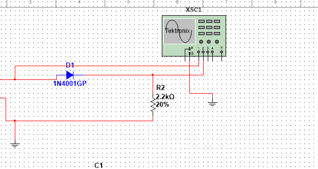
half-wave rectified filter circuit/oscilloscope measurement
Hello everyone, I hope I can get help on this fundamental issue, I'll have. University online, with which I will not help me, so I hope that I can quickly get assistance here.
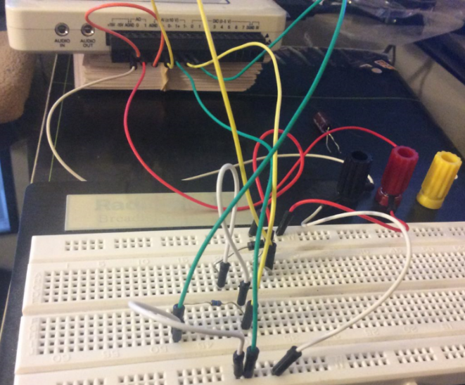
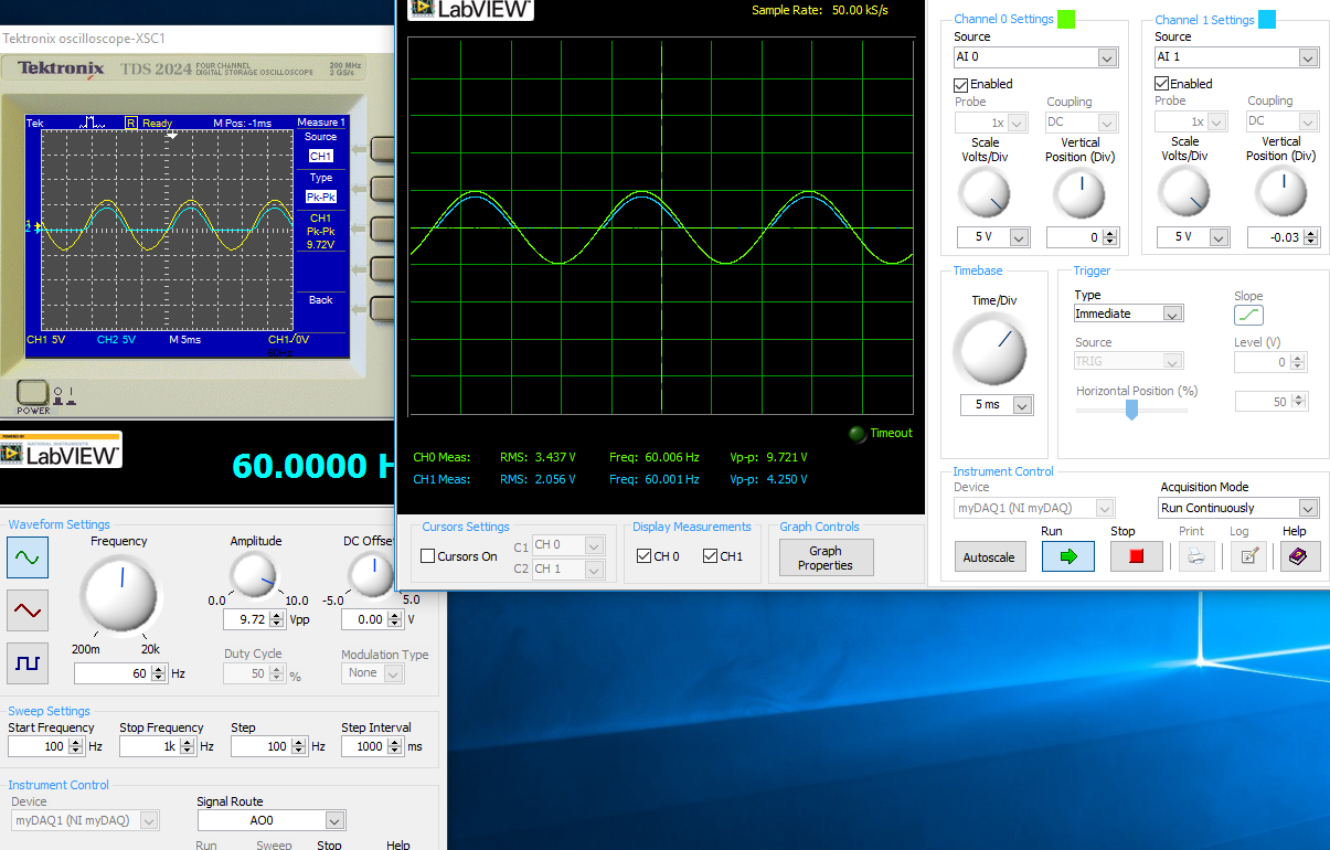
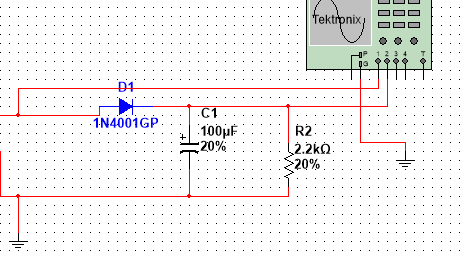
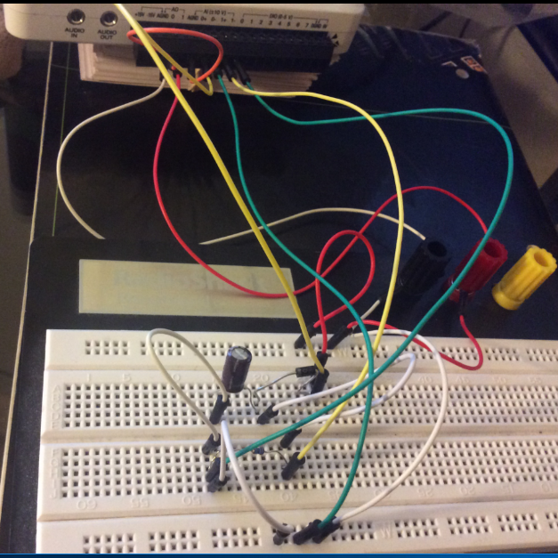
I have the myDAQ NOR, I have to build half rectified filter circuit with a resistance 2.2kOhm, I also use the multi-sim to confirm the measures of waveform. Everything goes well on Labview multisims Tektronix Oscilloscope compared to before I connect a capacitor 100uF my comparison heres:
The model is just the Diode with a series resistance 2.2kOhm, I'm not sure if the analog inputs to the LabView Oscilloscope are configured correctly this is the air I get:
This satifies my simple comparison on the Multisim circuit, since I came here for a few hours to play with probes analog input, I know that something is wrong out of these measures, I get.
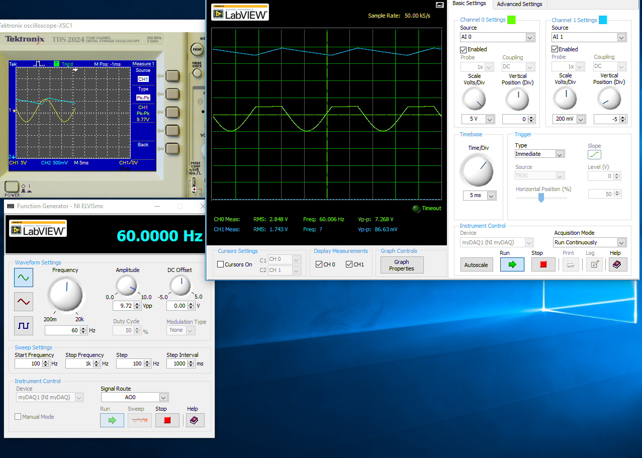
With a capacitor 100uF in parallel:
I think the question is how I inputs analog and STILL plugged, I'm not sure that this is where I would really like some help or any type of assistance. Once I get this set up right, I'll be able to take measures for the frequency, load DC, P - P Ripple voltage ripple and then move to a full-wave rectified circuit. I just started a course and received the myDAQ.
Henrik_Volkers wrote:
Compare it with the current specification of output of your myDAQ

Here is a link to the specification: http://www.ni.com/pdf/manuals/373061f.pdf
Henrik hit it on the head. The myDAQ can, at most, out 2mA with analog output. So, with a 2.2kOhm charge, which puts you in 4.4V without the diode. The led will also require an amount of current. According to my estimates, subject of 1mA (your pic is ~2.5V, divide by the 2.2kOhm to get ~ 1mA). You will see only that on the positive side of the sine wave as the diode blocks all the negative side.
The lesson here is to make sure that your outputs have enough power to do what you want. You can go to get a simple op-amp from digikey and use a follower of tension for editing the current upward. You will probably need another power supply or two (+ 12V and - 12V) to power op-amp.
-
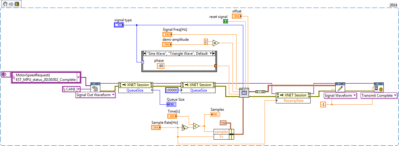
Size of the queue for Signal form write XNET
Hello
I am using the XNET library to play a preset on an output signal waveform. I work with LabVIEW 2014 SP1, 14.5 XNET on a W7 Pro 32-bit operating system. I use an NI PCI-8512 map. This is my first app using the xnet library.
In my test application, I give the user the ability to set the waveform to play. The total duration and the sampling frequency can be set. The output MAY report is cyclical, with a cycle time of 0.01 s (10 Hz). I chose to use the same frequency for example my wave form and writing of the CAN.
I have difficulty working with the size of the queue. In this example, it's good but I did not really why. I tested different values in the size of the queue and 100000 seems to be good up to 60 seconds. But for the longest (about 5 minutes), this method is not good...
What is the right way to work in this mode and how use efficiently the property size queue? Information and example of using software and hardware OR XNET are not very convincing...
Thank you in advance!
You can add several items at the end of the queue until the queue is empty. So if you want to write 10,000 points, and your buffer is only 1000 points, then wait and monitor the number of messages remaining in the buffer, and once it is less than 100 say adds an another 900.
I used this method for flashing on CAN and LIN. I needed a way to watch specific at specified times images, and a single point of frame link would not repeat (which could write the same byte twice what would be bad) I could have made the rivers and used avoiding, but a better solution was to use queue and add more pictures at the end of the queue to try to keep it as complete as possible.


Maybe you are looking for
-
Whenever I sign in iCloud, it asks me to allow or not allow my iCloud entry into one State other than that in which I reside. IPhone 6 and seem to me in New York and I live in New Jersey. How to make this correction?
-
Tecra R10 - how to remove the HARD drive?
Is there a description available hoe to remove a hard drive in a Tecra R10 and plugin a new hard drive?
-
HP-Envy-17 t-3000-CTO lw900av: HP-Envy-17 t-3000-CTO Msata SSD upgrade
I saw the following post and have a similar question http://h30434.www3.HP.com/T5/notebook-hardware-and-upgrade-questions/HP-envy-17t-3000-CTO-MSSD-mSATA... 665930-001 300 - GB SSD driveDisc SSD of 256 GB 689223-001 I have a 80 GB SSD, which I think
-
Data are not acquired due to a VISA error!
Hello, I had a something causing problem of ownership VI data acquisition. I have attached my VI in case you want to see my VI. When I tried to connect my VI assembled to the test, he didn't acquire data of it. The error has been shown "property Node
-
Where can I buy Microsoft Works with word processing, download/store?
A demon gave me a computer Windows XP Proffesional and I don't have Microsoft Works with any word processor where are you going to get the software, download/store? Help!