Resistance to the Earphonesocket?
Hello
can someone tell me the Ohm resistance to the extra - Sansa Clip 8 GB earpiece?
Thanks Gambler
Hello
Sorry my good isn´t, it s not my first language English. For me, resistance and impedance is quiet, I do not know now it s. thank you. Then the 16 Ohm's right. I need this 16 ohms as I build a miniamp for using the Sansa Clip with my normal amp, so that it is not necessary to turn the high volume.
Thanks again and
Greetings Gambler
Tags: SanDisk Sansa
Similar Questions
-
Read a resistance of the diode by vs NI USB multimeter
Hello
I read a resistance of the diode at some entrances to supply voltage
and I found that
to 0.2 V
the value of resistance by NI USB-6212: 200 ohms
the value of resistance of meter: 2 kohm
0.5 v
the value of resistance by NI USB-6212: 500 ohm
the value of resistance of the multimeter: 5 kohm.
Could you please let me know why the values are different by 10 times?
Thank you.
No - we can't measure the resistance in this way.
To measure resistance, you normally spend a current known and then measure the voltage. A DMM will be repeated by generating a little known current and measuring the internal tension. If you provide an external voltage thus, DMM internal resistance measurement will not work.
For the LabVIEW - The USB-6212 can measure the tension. If you want to measure resistance, while the unit is plugged, you need to know/measure current (for example through a shunt resistance) and the tension and then do R = V / I for the resistance. I don't know what the argument of type 6212 if you try to perform a measure of 'resistance', as it is not a source of internal current.
Oh, I thought that this all seemed familiar - here's a similar thread: https://forums.ni.com/t5/LabVIEW/daqmx-resistance-measurement-6251/td-p/3267084
-
Why can't acquire data from strain and resistance at the same time with a NI 9219 module?
Hello
I use a chassis with a NI9219 module 9172 cDAQ to try to acquire the strain and resistance at the same time, with the Labview SignalExpress software. Is this possible? When I try to display two values of signal at the same time, I get an error of assistant DAQ 50103 'the specified resource is reserved. The operation could not be performed as indicated. I used to be able to acquire the strain and tension at the same time, but now even that gives me error 50103. I have hours trying to figure this out. Any help would be greatly appreciated.
Thank you
Justin
That's all! Thank you very much, now I can sleep tonight - seriously!
Thanks again,
Justin
-
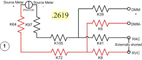
I have a problem with a PXI-2530 switch card work in matrix mode 4 X 32. I need to determine the resistance of the pairs of specific relay within the matrix. I have a PXI-4130 and a PXI-4071 in the same chassis, so I take measures 4-wire in a configuration like this...
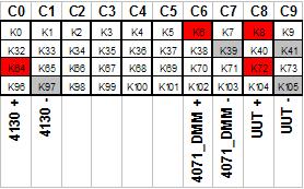
Resistance symbols represent relays in the switch. Here is a representation of matrix-style switch routes I use. (This should look more like the interface of soft face before switch)
The two diagrams represent so how I take my measure. I shorted outwardly columns C8 & C9 (shown in the first graph), I am sourcing 500 microamps of current and toggling the current source for a positive and a negative measure, I am able the voltage with the DMM. For the above measure I'm mesure.2619 ohms. This should be of course my resistance of the relay K8, K41, as well as Terminal block and wiring.
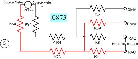
Here's another schema. This should measure the resistance of two same...
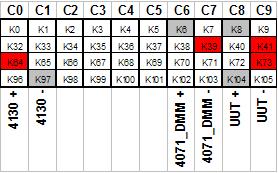
All I have changed is routing between the meter from the source. Here's the view from the matrix...
With this measure I'm mesure.0873 ohms. I can have the same resistance as the first example except getting a very different measure.
It gets even more interesting. If I had to take 4 pairs of wires, I use here, there are 16 possible configurations. I took each of these measures, and half of them gave me environ.25 ohms while the other half gave me environ.09 ohms. I tried this on a 2nd chassis and got the same result. My data are in the attached sheet. (My examples above are rows 1 & 5.)
Taking the measure of how we are, all these measures should be substantially the same. I have a current source constant, (I even tried a crimp in instead of the 4130 and got the same result.) and the meter is high impedance. If I had a pattern for the PXI-2530, I could do a little more analysis to know why I get various measures. Is there some diodes clamp on the lines or columns in the matrix? Something external must act solange this circuit. If I can find out what that is, I could determine my resistance to relay to a quantifiable level of uncertainty.
Any help would be greatly appreciated.
Greg
It seems that I can't remove. The correct message was placed here...
Once again, my apologies for the incorrect positioning of the post.
-
9234 sensor back to resistance of the chassis
My question is about the NI 9234 module and terminal return (HAVE) resistance to the chassis. On the side of the module, the diagram shows a 50 Ohm resistor to the chassis. However, when measured using a multimeter, the resistance is much higher (order 500 kohm.) I hope someone might be able to explain this discrepancy. My only thought is that, based on the data sheet, there are current limiting diodes present between performance and 50 Ohm resistance that may have an impact on the measurement. I don't understand how it would be possible, however. Any help is appreciated.
Page 11 of the Manual:
http://www.NI.com/PDF/manuals/374238c.PDF
Watch back to back diodes in series with the 50 ohm. They are probably affecting your measure if your DMM does not exceed the voltage of conduction of them (don't know what the specs are on the diodes).
-AK2DM
-
660 x Schematic of the low resistance of the menu drop-down
The 660 x data sheet mentions that the State of market has an entry (high Z) with low pull-down, but I can't find a diagram with this low resistance value of the menu drop down.
I want to measure a clock signal on my DUT without loading or distort the signal, so I intend to use a buffer. I am concerned about the current required drive to overcome unrolling integrated resistors and the requirements of threshold as a result of my meter PXI-6608.
If anyone has a link to the recommended buffers, levers of level or an article in the knowledge base with an example circuit, it would be much appreciated!
http://www.NI.com/PDF/manuals/372141b.PDF
It was working fine. I look forward to adding to my next PCB ITA.
-
Help, please! Experiment to measure the resistance of the contacts in the relay contacts
Hello
I am completely new to Labview and have been asked to try to use the software and hardware to develop a VI to measure how the relay contacts contact resistance deteriorates with thousands of cycles. I have succeeded in one NOR cDAQ-9172 containing NI 9219 and NI9472 modules interface and can access them through the DAQ Assistant.
What I want to know is, how do I activate the relay I test and turn off using a pulse and keeping a count of operations and at the same time a measurement (this can be in each cycle of 100 or 1000) and save it in an ASCII data file?
All I have at the moment is the documentation of OR and a book titled Labview for engineers and scientists by John Essick, who I work slowly through.
It's such a difficult task VI?
Best regards
Andy
You can have a digital task as an analog input task running on the same chassis. You just turn the digital output of the cycle the relay and read with your analog inputs.
DIO most did not have enough current to drive a relay, then you want to get a digital stamp which can provide enough power for your relay.
Oh and check out the free online training modules
Introduction of 3 hours
Introduction of 6 hours
Bases LabVEW
Paced self-study for students
Self Paced Training beginner to advanced, required SSP
LabVIEW training Wiki
OR learning
Getting started with products OR -
BI Publisher 11: decrease the resistance of the graph in the designer
Hello
We use Oracle BI Publisher 11.1.1.7.150120 (build # 20150113.1211 kill him Jan 13 12:15:48 THIS 2015)
can you tell me please how to decrease the hardness of the graph in the designer of BI, I enclose a sample Charter.
Best regards
Djam

I create an SR, and the solution is:
This is done via the property table:
With the layout template open in edit mode, expand the 'Properties' of the left frame section.
-Select the first 4 charts
-then Properties section expand the "graphic plot area.
-Select 'Series 1 line width' and enter the value 1 px
-Select 'Series 2 line width' and enter the value 1 px
-Select 'Series 3 line width' and enter the value 1 px
Djam
-
How can I use 2530 b and 4065 to measure the resistance between two selected pins?
I want to be able to select 2 corners on a test with 2530 b set-up and measure the resistance between them with a 4065 DMM (PXI all). Ankles in question are each in blocks of 32 different poles, so I can match them in a double configuration 32 x 1 four or 64 x 1 if necessary. I can measure the resistance between several different pine sets as 0 on 33 pine pine, pin 0 at pin 34 pin 0 to 35 pin and pin 1 to 34 pin, pin 1 pin 36, etc.
I understand how to measure resistance between a given pin and Earth using the the 2530 4065/b using the wizard OR-DMM/Switch Express, but it is unclear if I can measure the resistance between the two pins of selected by different user. I am a newbie of labview, used to write things in c#, so it may be something very trivial (I hope).
Any ideas?
Thank you
-Russ
Hey Russ,.
I recommend starting with the following example (located in the Finder the example ('Help' to find examples):)
"" Material input and output"Modular Instruments ' OR-Switch" niSwitch Dmm Switch Handshaking.viBecause you use a scan list, you can simply drag the two connections to the same entry and then the switch will wait for the two to settle before you send a trigger of the DMM... problem solved. For example, to connect the CH1 to Com0 (DMM +) and CH93 to Com4 (DMM), then take a measure, then connect CH38 and CH120 to the DMM, you would use the entry list of scan to the following address:
CH1-> com0 & ch93-> com4; CH38-> com0 & ch120-> com4;
Note You can have as an entry in list of switch module scan. In addition, you can only have a single advanced analysis and a measure full per switch module.
-
change the footprint of the resistance
I would change the footprint of the resistance for a student laboratory where the pads need to be made larger than normal size. I can't find a good match in the footprints of existing resistance. How can I add a footprint artisanal to the resistance of the virtual component?
What I read on http://zone.ni.com/devzone/cda/tut/p/id/7321#toc6 regarding the backward annotation confirms what I discovered:
"the process of back annotation has limits to what changes can be actually transferred to the schema.
-
USBOTG and Charge at the same time on Stream 8
To keep this thread as productive as possible and efficient for those who find it useful to:
Unless you have under your eyes
1. a schematic representation of the 8 Stream USB port (USB port and battery electric circuit etc.)
2 source code for the firmware BIOS and kernel that controls the material
Please DO NOT respond or say "is not possible". In view of the above is true, you do not have enough information to say '' not possible. ''
If no one replys with a solution, what he calls not possible by default.
Also please do not answer to say ' I don't know how "or" but I know how to do anything else that ' is also not that useful.
An update of the BIOS or other software update may be required by HP, Microsoft or both to offer this feature really intuitive and quite possible.
And I hope that this thread can be an effort consolidated by all who have the 8 flow to make the necessary changes. The majority of the other tablet PCs are capable of it. It seems that only the 8 Stream and a few others have trouble with her.
~~~~
I want the ability to use a simple, inexpensive cable and perhaps standard (with electronic active minimum inside) which allows me to host and to use one or more USB devices on the Stream via its USB port B microphone 8 while this cable can also be connected to a charger standard and charge 8 flow simultaneously. This means that the cable has a minimum of three connectors. One of the possible configurations are as follows (apart from the normal charging cable):
1 cable Micro USB B Male - connect to the stream 8
2 USB male A - connect to the AC charger (IE one that came with the 8 Stream)
3. USB A female - one or several connectors to plug into the key of USB data, keyboard, mouse or even a hub.
Connector # 2. above shall provide a power supply to recharge the 8 Stream via conn. #1 and the power supply for external USB devices via conn. #3 so that they are in use - all at the same time.
A and if the same cable can act as a normal OTG no charger for when no external power supply is available. This may necessitate a switch or an electrontics active inside.
The last part of this goal is unimportant for various reasons. I wish that HP, the manufacturer of 8 flow, to State in writing good mode necessary to do this, so that other manufacturers or even-it yourself can make maximum use of their tablet HP equipment.
~~~~
The neat thing it will alow a person to do with their tablet, it is to work at home using the Tablet as a desktop PC by connecting a keyboard, mouse, perhaps external screen (with USB to the display adapter) and knit for a long time without time limit prescribed by the battery life because the charger provides energy to all involved.
If there is only a single connector on the cable #3, then an additional node of coarse had to provide support for these multiple USB devices at the same time. However, it would be better if there were several #3 connectors integrated in the cable itself. This would be better as a suitable USB hub also requires its own power. That an adapter is necessary if the whole thing were integrated into one.
~~~~
I really want answers from anyone who has already accomplished USB OTG delivered with simultaneous load with flow 8. (independent of any published 'proper' way is also welcome)
Today's date is 2015-01-16. If in 2015-02-16 (one month), nobody has posted a solution and then starts to bug HP and Microsoft on it's us?
~~~~
Technical training:
I understand the possibility the tablet software and firmware must take a decision on the manner in which power flows on the power port USB microphone B pins.
I know that with a proper design of the electronic circuit carring these signals of power inside the Tablet could be sensitive to what is connected and without risk to decide for himself what to do without needing to control software. For example by testing/detecting periodically differential voltage or current management to see what sides of the connector can supply.
But this is only one of the many "could bes".
In addition, this can be no standard regarding the standard USB. What seems to be actually the case with a lot of cables OTG + fresh, is that physical clues embedded in the cable or charger are used to signal to the Tablet what the situation is. Then the signal of software/firmware of the Tablet, interprets what the situation is intelligently and responds by flipping the bits of correct hardware control to activate, or deactivate the power flow in the port and also control its direction in or out.
I'm not familiar with the standard USB. Maybe I could do more research, if I believed that HP followed with 8 Stream or even the standard covered this situation explicitly.
But to a certain extent, it seems I'll have to invent something that should be intuitively just like it does with other tablets. Isn't it? Maybe I'm overthinking, but I can't find any USB OTG + cables load that specify compatibility with 8 HP flow.
In any case, I was familiar with both methods other use of tablets to send the highest mentioned signal to the hardware/firmware/software of the tablet to the idea that it's time to load / time of OTG or both.
The first method is a 0 Ohm to 200 ohms short between pin USB A 2 and 3. This is the bidirectional data differential lines D - and D + respectively. In data mode, all the data passes back and forth on those lines. When you load with a cable, it's the charger module that puts this short, not on the cable. I measured the short on three different Chargers. It is 0 Ohms on two of them, one of those who are the charger that came with the 8 HP flow. The others 0 ohms was generic. The third was for an apple iPad and it measured on 53KOhms. It's probably not the resistance ohms 0-200, but probably it is impedance termination indicating that there is some intelligent serial port communication in the charger itself. Leave it to Apple to be different.
This method is somewhat questionable, as this signaling mode would prevent OTG + fee because it seems unlikely that you will be able to OTG when the data lines are shorted each and overloaded with such low impedance. I could be wrong on this subject...
The other method I have seen suggested to work with some tablets and phones other than the 8 stream is too short the USB microphone B pin 5 to Terminal 4 with 0 Ohms to 100 000 Ohms.
USB B has 5 pins. USB has only 4. The extra pin on B moves the GND pin 4 pin 5 pin to and makes pin 4 PIN ID.
If this signal applies to a drop in the ID pin (4) or in some cases, I saw that she proposed, he runs down with 0 Ohms.
Dead shorting things always makes me nervous. If ID is a simple normally high impedance high input, resistance could be used to make voltage well below the low or zero threshold while also preventing the risk of damage when cheat on him with a device that you do not have the diagram for.
Yet, 100K is a bit high for a 'pull down' in most of the situations that I'm used to. Even a 10K would be uncertain. A 1 K or 2 K seems reliable enough, but then things are weaker and in know more nowadays low... All but a dead short but if possible.
So, it seems possible that the device might be able to "indicate" by the specific value of the resistance, which can be found here. In other words the resistance is not a pull down but in fact a signature analog ID, in which case the exact value will be crucial. So if this is the case, a guess is not going to work.
Obviously in such a system as described above, a chip inside the Stream 8 should be responsible to support this information. I hope the 8 Stream has such a chip.
Probably a register inside this chip would be at all times what the State of the pin ID is a binary number. All that is needed is for the BIOS to the chip and the registry in it and read this number via the bus to determine what happens to the port. Finally, he would use that signals of info to send the order of material to the electrontics of power set the appropriate direction to take etc. (and change the State of the icon on the screen of the rude)
I don't know if the PIN ID method described is a standard USB or not either.
Eventually, there may be a third way. But I do not suspect that it would be possible with a non-active external device. In any case too complicated for the novice DIY for sure.
The device would need to act is a kind of extension of bus. As an active hub. But she would use the negotiation of data USB serial lines and in addition to reproduce one or more additional USB ports, intelligently inform the tablet to get with the program which is "now we're going to otg and recharge at the same time."
This requires a smart external device with a processor Inside, no doubt.
It seems to me that many other tablets have been able achieve avecjoint here the need for a smart external device and thus the flow must also be able to do.
There is a device that claims to be able to work with the HP Jet 7 and 8 and provides same ethernet and USB and big DVI ports so loads the data stream. But its expensive because it is active. Se here:
It's called a "Docking Station".
A reference to a product that does exactly what I want (possibly without active electronic components) is here:
It's by Kirin and it is a device of type squid with four USB ports. Precisely, which is my goal. But read in the comments stream 7 user indicated that he would not be OTG and load, not really clear if it worked as a hub USB OTG or not. Another evaluator stated that she would not support even a single USB device much less fees of 8 Stream. This device has a switch.
I forgot to mention that some 'hackers' have claimed success with other tablets to deceive their devices by using a multi-step process to plug things in. Usually in general they would get connected Tablet and load first, then they would return a switch or something remove some resistance or the signal was introduced by the first position of the switch. For some reason any Tablet would continue to require. Then the data lines would be free and they would plug in a usb key and it mounts correctly even if the tablet was always in charge.
It's like the power circuit has a lock which does not allow it to return to the mode "power flow" as long as he still feels the power flows inward regardless of what software it is telling. Full proposal here.
These tips seem dubious to me. Changes in the BIOS could change the way it works. Also you can not be sure what actually happens if you do not have a schematic representation. You could damage your tablet. Many people will support icon in the operating system whether the Tablet is in charge. But I'm sort of a low-risk guy and my policy is generally indicators of intereperet not to have meaning at all once a device is functioning in a non-standard setting. Especially when it's something that I did not built and could not fix if I FRY.
Hypothetical reasoning: tell me what data sensory discs really the State of the charging light screen? This reflect the bit of hardware control programs actually feeding management and status on the port? Or does it measure the direction of the flow of power, said in the section of the circuit battery monitoring? Point - none of us have a schema because it's owner. To really be sure according to the smart electronic hardware, the port must be mode flow under advisement "of power. If it's in a "power flow out" mode and power will be delivered externally as well you wind upward with both power supplies the same power at the wheel nets. In this case, the two opposing regulators attempting both to drive 5 V can have slightly different voltage calibrations. That could lead to fighting between them, with more than 100% of their capacity. For example if you try to regulate 4.95 real V and the other and other attempts to regulate 5.05 V. Current then flows to the tune of 100 mV / a few milliohms in the cables linking the two. This may be several amperes. (many) In other words, like I said: you want the tablet to know that power is coming in don't go out and automatically hitting the internal switches needed for that to happen. Probably the icon should indicate this with precision, but in some wacky situation, he could not. There may be a chance that the icon could indicate the load and still be burning or focusing on some circuits of the tablet or the charger.
Another thing, I could see that happening is if you play with these reported resistance types enough you might find a resistance value that winds up place the device in an intermittent condition. In other words it keeps flipping back and forth quickly between OTG and fresh. It can give the illusion that it works. You can have marginal communication with your USB devices and battery could even load. But will still be a lot of stress on the power circuit.
It is difficult for me to risk a Tablet perfectly well if I don't know exactly what I'm doing.
If a brave individual makes their own experimentation and verifies that it charges and OTGs and you tell the rest of us, you're a hero.
Maybe one of you has a good knowledge on the USB standard to have more confidence in such an experience... like what the ID pin 4 REALLY supposed to work for example?
That's what I know so far. If you think you can help, thanks in advance, or if this helped you, then your quite welcome.
It works
Evidence
http://targusblog.com/2014/11/25/how-to-turn-a-99-Tablet-into-a-workstation/
But it's 4 x the price in Europe
Have fun
-
Satellite 2450 - the display hinges loose
The screen on my Satellite 2450 lost its resistance on the hinges, its either fully open or fully closed and will not be held in position.
The speakers or the other side of the hinge have lifted a bit, I can get in and repair the damage?
Hello
I'm sure that it is possible to fix it. But I think you need new hinges.
These parts, you can order from Toshiba service partner in your country.
But without any experience, it is not very easy to replace.
I recommend you ask guys to service for advice and guidance.
Do not remove anything, if you n? t know how to do this. -
Does anyone have ideas if you can wear the Apple Watch in a water park
Electroisolante afternoon guy, is - anyone haz of ideas so you can wear the Apple Watch at a Waterpark? Please give clues of meh that I'm about to get a Apple Watch for my birthday
Hello
Apple Watch is splash and water resistant but is not waterproof. You can, for example, carry and use it during the year, in the rain and all washing their hands. Immersing, however, is not recommended and any water that splashes on the watch must be wiped with a nonabrasive cloth and lint.
Apple stated that, for example, may affect Apple Watch water resistance and should be avoided:
- Swim or bathe with it.
- Immersing in water for long periods of time.
- Expose to water under pressure or high speed (for example, showering, water ski, wake Board, surf, jet ski, etc.).
None of the bands in leather are water resistant. The watch water resistance is not a permanent state.
More information:
-
Pavilion 15 bj000nh: very low wifi on the brand-new Pavilion 15 bj000nh
Hello everyone, I have a problem with my new laptop purchased 15-bj000nh HP Pavilion, a few days ago.
The wi - fi connection is too low, that if I keep the PC one meter away from router I get only 3-4 bars of 5 in the connection properties and if I go to 10 meters and a pair of rooms up to now I get 1 to 2 bars of 5 and frequent disconnections. Also the speed breaks I see, and close to the router is too not at the maximum.
Otherwise, my old laptop HP 6735 s with Windows 7, never had problems in the same position (10 m) and keep 3-4 bars no disconnections. I checked the resistance of the router wi - fi with mobile phone too (not), I tried all the solutions offered by HP support assistant on PC and on the HP support site also, but with no result... I have the card (802.11n) Broadcom software upgreaded. IT helped a little, but even with the latest software, my laptop has connectivity problems. I can't believe that a new NB may have a weak connection... I have some other ideas of a HW fault...
Thanks for your help.No wireless card will work well with only a single antenna and a dual band (2.4 and 5 ghz) won't work at all on a single antenna... An aerial cable can be added, but it takes almost complete disassembly. I doubt that the Service would do. I wish that it is something that I could tell you. A usb wireless dongle is your best option. $ 15 on amazon.com and you will have good reception at the cost of losing access to the usb port.
-
I have a question for the SMU 4139.
It is able to program the output resistance/impedance.
Its output can be used to simulate a resistance? Floating? Or he is still stuck to the ground.
THX.
Hi kdCMC,
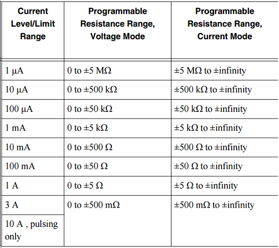
You can program the 4139 NOR as a programmable load. The attached example allows you to use the functionality of the programmable output to the program directly resistance the resistance of the device. To do this using the DCV, set the output voltage to 0 V and the resistance value of the output to a value valid for the given current limit range. DCI mode, set the current 0a output and the output resistance to a valid value for the given value of current level range.
Valid values of resistance are shown below (copied from the technical document):
Note that valid resistance values depends on if you are in mode voltage or DC current. The value of values also depened on the current limiting current level range or that you have programmed.
The load will always float unless you physically short the LO Terminal to the chassis GND.

Maybe you are looking for
-
my ipod touch does not appear in itunes (windows). Everything has been updated and rebooted.
I'm extremely frustrated that I can't get my ipod touch to show up in itunes12. I've updated the itunes software on my PC. I have to update the software on the ipod touch. I tried 4 cables different (all Apple) and rebooted several times. Out of my m
-
The 1473R CAN be used with the real-time operating system of NOR?
Hello, I am trying to determine if I can use the OR 1473R framegrabber PCIe FPGA in a PC based computer time real OS OR. Anyone know if this is possible? So I think that it should appear to the OS in real-time as a target FPGA that can transfer the d
-
Impossible to get rid of a file folder
I tried all the stuff I could think of, including safe mode, in order to delete a folder of files from my T61p (Windows Vista Home Premium) without success. I have powers of the administrator, but they seem not to be good enough for this particular u
-
Is there a way I can recover my Outlook Express e-mail account. I downloaded Windows Live Mail and don't like it at all. I can't understand how to add a new contact.
-
Hello. I just got a very useful answer to a question about file Pareto Logic Cure. Maybe someone could help me with this one... It takes FOREVER for my e-mail, in soundcards Live, fully open so that I can access it. He always tells me he had problems