Running in emulation in Labview FPGA VI 2009 Mode
Hello
How can I run the FPGA VI in Labview 2009 emulation mode so that I can run VI FPGA before compiling?
Thank you and best regards,
Rashid
Hello r,.
You have a 5640R or another card based R-series? I'm going to assume your VI FPGA makes equipment to a 5640R calls due to the
Forum in which you've posted. If this is the case, because of the architecture of
Screw model, the emulation mode is not supported in NOR-5640R. If you want to
emulate your logic and no appeal of material, it is possible, but it can also be
fact in a host of vi.
Tags: NI Products
Similar Questions
-
Rate of update NI 9025/9113 IO using FPGA in scan mode
I have an old CRIO manual indicating that the scanning speed is 1 kHz. The new materials (9025 and 9113) can go faster than 1 kHz?
Page 17 of CompactRIO Developers Guide will give you the best explanation. Anything more than 1 kHz will have serious consequences on your CPU usage. It is recommended whenever you want to run the application using LabVIEW FPGA programming faster than 500 Hz rates.
-
Hello I want to run a Stepper with 7851 FPGA R card with driver 9474 crio chasis, but I'm not able to understand how to proceed. Or may choose this option by using view lab CVI
Hi VHS.
first of all, I would recommend that you want to use materials. Basically, to control a stepper motor, you have a controller of axes and a player.
In fact I don't know why you want to use 7851 R card and cSeries 9474 module. In any case, you can connect the FPGA Board with an NI 9151 expansion chassis for
Plug the 9474.
In the following link, you will find basic concepts on control of engines with NO motion:
Motion Control fundamentals
http://www.NI.com/white-paper/3367/en
In addition, you need a software application. NEITHER offers LabVIEW - graphical programming and LabWindows CVI language - it is a system of development in C-ANSCI
for C programming.
Kind regards
RupiDo
-
Spartan - 3 driver and Labview FPGA 2009
Hello
Do we need a new Spartan-3E driver to work with Labview FPGA 2009? And, if so, is it provided by National Instruments?
Thank you
Walid F. van
Hello everyone
The driver for the Spartan 3rd WHAT XUP Starter Kit are now on the site OR here:
http://digital.NI.com/express.nsf/bycode/Spartan3E?OpenDocument&lang=en&node=seminar_US
Just click on the link to get driver.
Kind regards
John Harvey
-
Internal software error of LabVIEW FPGA Module - 61499
I get the error next (in a pop-up window) in the phase of sompilation for the FPGA target with a vhdl IP. This error continues to occur even after restart LabVIEW and the PC. Someone at - it solved is this kind of problem before without having to re - install the software?
Here is the error information:
Error-61499 occurred at niFpgaXml_GetValue_String.vi<><><><>
Possible reasons:
LabVIEW FPGA: An internal software error in the LabVIEW FPGA Module has occurred. Please contact National Instruments technical support on ni.com/support.
Additional information: lack the tag required XML (/ CompileServerList)
As a first step, I can compile the vhdl IP node successfully. However, once when I'm running a VI with the FPGA, the bureau stop working. After that I restarted by force, it cannot perform the build of a vhdl IP node. Even without connecing to the jury of LabView, he pointed out errors before the end of the sompilation.
Interestingly, the screw which also includes nodes IP vhdl that I properly compiled before, I can still run the VI to the Commission and it works correctly.
Thank you
Looks like your ActiveJobsList somehow has been corrupted. I saw occur when computers are hard stop or blue screen during compilation. I don't have that LabVIEW 2014 installed on my machine, so your path will be a little different, and the file extension will be a .txt or .xml instead of .json, but try this:
Move the file "C:\Program Files (x 86) \National Instruments\LabVIEW 2014\vi.lib\rvi\CDR\niFpgaActiveJobList.json" (or your equivalent) out of the above directory (back it upward and delete essentially) and restart LabVIEW. Must regenerate the file and resolve the problem.
-
How to measure the frequency of sampling (s/s) in LabView FPGA?
Hello
I am trying to find a way to measure the sampling frequency (s/s) during which I read from analog input in LabVIEW FPGA. I know that the sampling frequency is specified in the data sheet of the module HAVE, but I want to measure in LabVIEW.
Any suggestions?
A screenshot of the example code would be greatly appreciated
Hey phg,.
If you have some time loopand in this loop, you export a sample by iteration of loop via an I/O node. You can't out two samples on the same I/O node within an iteration, it's always one!
So if your loop takes 1 second to run you have a sampling rate of 1 Hz output. The same goes for sampling of entry. How long your loop takes to run can be calculated as explained above.
Samplerate [s / s] = 1 / [s] while loop
-
LabVIEW FPGA: Integration node clock wrong
Hello
I'm having some difficulties to understand how the clock is part of the node IP for LabVIEW FPGA and was hoping to get some advice.
What I try to do is to set up a digital logic circuit with a MUX feeding a parallel 8-bit shift register. I created the schema for this Xilinx ISE 12.4, put in place and can't seem to import the HDL code into an intellectual property node. When I run the VI, I am able to choose between the two entries for the MUX, load the output in the shift register, clearly the shift register and activate the CE.
My problem is that when I switch to the entrance of THIS, he should start 1 sec shift (Boolean true, SCR, High, what-have-you) in the registry once each clock period. Unfortunately, it instantly makes all 8 bits 1 s. I suspect it's a question of clock and here are some of the things I've tried:
-Specify the input clock while going through the process of configuring IP nodes.
-Adding an FPGA clock Constant as the timed loop.
-Remove the timed loop and just specifying the clock input (I'm not able to run the VI that I get an error that calls for a timed loop)
-Do not specify the clock to enter the Configuration of the IP node and wiring of the FPGA clock Constant to the clock input (I can't because the entry is generated as a Boolean).
-Remove an earlier version of the EC who had two entries up to a door and at ISE.
-Specify the CE in the process Configuration of the IP nodes.
-Not specify this in the process of setting up nodes IP and wiring it sperately.
-Various reconfigurations of the same thing that I don't remember.
I think I'm doing something wrong with the clock, and that's the problem I have. Previously, when I asked questions to the Board of Directors on the importation of ISE code in LabVIEW FPGA, a clock signal is not necessary and they advised me to just use a timed loop. Now, I need to use it but am unable to find an explanation online, as it is a node of intellectual property.
Any advice would be greatly appreciated, I'm working on a project that will require an understanding how to operate clocks the crux of intellectual property.
Thanks in advance,
Yusif Nurizade
P.S. I have attached my schematic ISE and the LabVIEW project with one of the incarnations of the VI. The site allow me to add as an attachment .vhd file, but if it would help I could just paste the body of the code VDHL so just let me know.
Hello Françoise,.
I spoke to the engineer OR this topic and it seems that it was sufficient to verify that your code works, by putting a wait function of 500 ms on the while loop to check that the registers responsible and clear. I'm glad that it worked very well!
-
Drivers Xilinx/Multisim and Labview FPGA
Where can I find drivers for my FPGA OR if I use Multisim/Xilinx and NOT of Labview? All the links I found are Labview be installed. However, the explicit manual FPGA indicates that you can use Multisim/XIlinx ISE in place.
OK, I tested just outside. The Driver of LabVIEW 2013 DEFB contains 2 separate components, the driver and Module FPGA support. If you run this installer, it won't check if you have LabVIEW FPGA installed unless you check the box for LabVIEW FPGA support.
I can change the text in the Installation Instructions to read "LabVIEW FPGA 2013 is required to install the LabVIEW FPGA Module Support component installation".
-
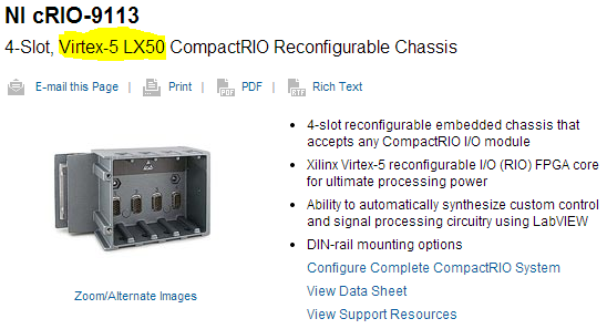
Download NI LabVIEW FPGA Module Xilinx Tools 10.1 2013 problems
I'm trying to download the Xilinx tools 10.1 to use with a chassis 9113 in LV2011. Based on this white paper, that the compiler below should work perfectly. The problem is that I can't seem to download all the way.
I can't seem to cross ~ 336MB using the standard or the downloader OR. Any ideas? Does anyone else have this problem?
http://www.NI.com/download/LabVIEW-FPGA-Module-2013/4249/en/
Thank you
-PBD
Well well... on the good side of things, you don't want 10.1 anyway!
Virtex-5 LX50 FPGA<- requires xilinx="">
10.1 is only for devices FPGA Virtex-II! (.. .after LabVIEW 2009 it was, just for all of you who read this know).
so... try this link: http://www.ni.com/download/labview-fpga-module-2013/4248/en/
-
LabVIEW FPGA: Problem compiling look-up Table
Current versions of software:
LabVIEW 2014 SP1
LabVIEW FPGA 2014
Xilinx Vivado
I'm having a huge problem in trying to compile my LabVIEW FPGA code.
Some recall of the code:
It's all in a SCTL.
I am streaming in a FIFO DMA and comparing it with the values previously stored in the shift registers (which are initialized to 0 at the start of the loop) in the SCTL.
The results of the comparison are then piled into a U16 and loaded into a lookup table (I use the LUT - 1 d), and I'm so help this LUT to decide what value will be charged to travel to record for the next iteration of the loop, which, in any case, would be either the current values of the flow, or the post previous registry value.
(It's a triage loop)
I am able to run very well in simulation mode code, but when I try to compile, I get this error:
"The selected object has a built-in shift register that makes the output on a particular loop iteration correspond to the entries in the previous iteration."
Connect the outputs of the object directly to a minimum number of nodes of Feedback or uninitialized shift registers. You cannot connect the outputs to another object.
See using LabVIEW for more information on the objects with registers embedded offset. »
Someone at - it ideas why this happens, and what might be the possible solutions?
I'm tempted to break it down into separate loops, but I prefer not to because it is now a loop (and working in my simulation).
I found my problem.
Any time that a LUT is in a chain shift register, it cannot:
1. be part of a string of shift register that has a variable initialized
2. follow-up to no decisive structure, like a box structure.
I just moved the position of LUT and it works.
-
Run an application of LabVIEW 8.6 in win 7 (using the cDAQ-9172, 9219, 9422)
Hello.
I did a LabVIEW application for a few years. At that time, I used windows XP and labview 8.6. The material used is the cDAQ-9172, with NEITHER-9219 (reading of four strain gage sensors) and a NOR-9422 (using only a single input frequency).
First of all, can I install my old version of labview 8.6 in my 64-bit computer to windows 7? I got an error message when I tried...
Second, how much should I install? My old computer was slower after you install labview with its pilots. Perhaps I installed too much? Do I have to install 1, 5 GB DAQmx drivers?
If I need a new version of labview for win 7, how much is an update?
Thank you!
Hello
First version of LabVIEW which is supported on Windows 7 is LabVIEW 2009 SP1.
Regarding the drivers, if you want to develop or run VI:s in LabVIEW with the DAQmx API, then you must install the full DAQmx driver.
If you only meet built executable in the LabVIEW environment to run, then you just DAQmx Base Runtime.
If you also want to be able to configure the data acquisition equipment (to the MAX) in a runtime environment, you should also Configuration DAQmx execution.
For upgrades of licenses if please contact the local office of National Instruments or follow this link:
http://ohm.NI.com/advisors/UA/pages/UA/intro.XHTML
Best regards
Klas Andersson
OR Sweden
-
Hello
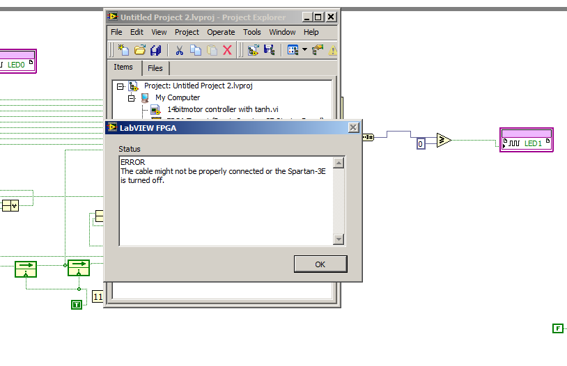
I'm trying to interface labview fpga to 2012 with Spartan E 500
I am facing two problem
a first in the figure below when I try to download Flash memory of Spartan E?
I run vi on Spartan works well but when I download it the error appear
also there is no "" "run when loading" "button which are available in a previous version of labview.
Please help
I don't have a LVFPGA version with the support of 3rd Spartan installed in front of me, so I'm working from memory here, but the option to run the VI on charge moved to the target property page (available on a right click on the target'Properties) of the standard build for the VI (as shown in your own message here)
-
Compilation of the variable results in LabVIEW FPGA
Hello. I would ask why LabVIEW FPGA generates different results of compilation for the same code. When I compile several times my code, the maximum speed and total changes bitfile slices generated according to the compilation, but I does not alter with the FPGA VI. In addition, is the precise relationship of compilation? Thank you
It's normal. The FPGA compiler starts to place pieces of code on the FPGA somewhat randomly and adjusts them until either the design adapts and responds to the criteria of the moment or there that the compiler determines that it cannot fit all the code and meet time constraints. The outputs that the FPGA VI generates when run will always be the same.
-
Can someone provide details on this known bug Labview? I can't find someone else who has experienced, and I would like to know what is the solution.
http://www.NI.com/PDF/manuals/374737a.html
412592
Cannot run VI FPGA in interactive mode (run button does nothing) if LabVIEW by default directory has been changed.
Well, it is set in 2014 of LabVIEW.
The problem is described in KB 4W7H2TNX: http://digital.ni.com/public.nsf/websearch/EF29C73D69B4887E86257592007C5AE5
It seems that the problem is exactly what describes the title, in that you could not run the FPGA VIs interactively if LabVIEW has been configured to a default directory.
-
Model a block synchronous dual-port RAM with LabVIEW FPGA
This question caught my attention recently.
I am trying to model a particular design element called "RAMB4_S8_S8" with the LabVIEW FPGA module. This element is a block synchronous dual-port RAM allowing simultaneous access to two ports independently from each other. That being said, a port can perform read/write operation to this RAM while at the same time, the other port might be able to do the same thing. There are two opportunities of possible port conflict, however. The first is when both ports are trying to write to the same memory cell. The other scenario is when a port writes in a cell memory while at the same time the other port reads from it. Other than that, everything should be a legitimate operation.
In order to reproduce this I select memory block that is integrated into my FPGA target. An interface is configured to be the playback mode, and the other is set to write fashion. For the option of arbitration, I let the two interfaces to be "arbitrate if several applicants only. Then I got a compiler error when I tried to run my FPGA code for this model in a SCTL. The error message is something like "several objects to request access to a resource through a resource configured with option interface" arbitrate if several applicants only ", which is supported only in the single-cycle Timed loop if there is only a single applicant by interface.
This error goes away if I replace the SCTL with a simple while loop, but not what I would like to implement. So I wonder if there is a better solution to this problem, or is it just the limitation of the LabVIEW FPGA module.
Thank you.
Yes, you can use a form of conduct to perform the operations you want in the generations clock cycles, but all the code is inside a single SCTL. Basically, read the first address and storing in a register in a single cycle and then read the second address in the second clock cycle. This would allow you to two readings of valid memory every clock cycle 2. I have included a crude extract to illustrate the concept. The case selectors are identical with address A being connected to the memory in the true case, B in the case of fake address. Your biggest model memory dual port will be intact, but it will operate at 1/2 rate.
Take a look at the white paper that provides more details on the construction of memory:
Data on a target FPGAS (FPGA Module)
The ball on the memory block indicates that memory block double port cannot be applied in a configuration of reading, which is a double ROM. access read/write port must be imitated with custom code.
Maybe you are looking for
-
Problems with Gmail on iPad Air2
iPad Air2 abruptly stopped, sending notifications for GMail. I have to open the mail application, choose gmail, open Inbox and pull down to get new messages. I tried soft reboot, hard reboot and uninstall reinstall gmail. Any suggestion would be appr
-
Pop - up stating that my Macbook Pro the virus-infected
Saturday 5 March, 2016, I got a strong voice popup stating that my Macbook Pro has been infected by a virus and it has been possible for hackers to access my files. I tried to close several times several times and there was no fence. Don't know how b
-
I need the (* address email is removed from the privacy *) account closed immediately. She has been compromised and now blocked. I changed the password several times now and it always sends me on this page of the blocked account where he asks your mo
-
Is it possible to download first 2015 v 9.0.1?
I am running the most recent version of first on a Mac Pro running the most recent version of Mac OS x. I'm in collaboration with another Publisher.Here is my question: is it possible to download and use the CC2015 first 9.0.1 device?This is the reas