LabVIEW fpga 2012: problems
Hello
I'm trying to interface labview fpga to 2012 with Spartan E 500
I am facing two problem
a first in the figure below when I try to download Flash memory of Spartan E?
I run vi on Spartan works well but when I download it the error appear
also there is no "" "run when loading" "button which are available in a previous version of labview.
Please help
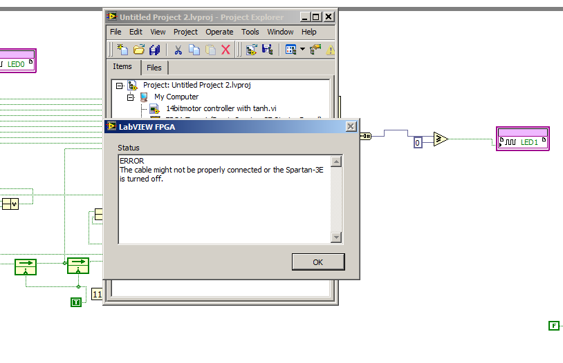
I don't have a LVFPGA version with the support of 3rd Spartan installed in front of me, so I'm working from memory here, but the option to run the VI on charge moved to the target property page (available on a right click on the target'Properties) of the standard build for the VI (as shown in your own message here)
Tags: NI Software
Similar Questions
-
LabVIEW FPGA SP1 2012 & EVS1464RT FPGA IO
Hello
There seems to be problems with the new Labview FPGA 2012 SP1 in combination with an EVS1464RT embedded Vision system, which took place only after upgrading to SP1 2012 Labview:
- While trying to compile our code for the EVS1464RT FPGA or (Vision system embedded with e/s based on a FPGA Virtex-II FPGA) Xilinx tools (V10.1, since it's a Virtex-II FPGA) has reported an error saying that the compilation work has tried to set the property 'Data (output events)', which does not exist, so the Xilinx tools just quit with an error.
A complete uninstall and reinstall 'clean' do not solve the problem.
Research has shown that there is a property correct for Xilinx tools, called "done (output events)." An extended search in the Labview upwards 'incorrect data (output events)' some text files in 2 files "resource.xml" in the directories '...\National Instruments\LabVIEW 2012\Targets\NI\FPGA\IMAQIO\IMAQIO-1 "and '...\National Instruments\LabVIEW 2012\Targets\NI\FPGA\IMAQIO\IMAQIO-5' (and nowhere else).". " Change these 2 texts to 'Done (output events)' corrected the error and allowed to compile the code again.
- Another problem is that you can not start the VI FPGA-interactive (for example by clicking the Run button). This product just another error message saying that the VI '...\National Instruments\LabVIEW 2012\vi.lib\FPGAPlugInAG\IMAQIO-5\niFpgaOpenAndRun_IMAQIO-5.vi' could not be found (and there really is not anywhere on the hard drive).
The FPGA VI can be started from an another VI on the target host by using the function "Reference open FPGA". Then it works without any problems, so the bitfile has been obviously compiled correctly.
All of this worked out of the box without any problems on my old installation of Labview (before 2012 SP1 update).
The first problems now seems to be a simple typo, and using the function "Open FPGA reference" is a workaround for the second problem. But I'm very angry that National Instruments does not seem to test their software before releasing. A service pack should never break things that worked before.
Find these alternatives cost me 3 days, which, in my opinion, could be acceptable for open-source software, but not if you pay hundreds of euros per year for a "Standard Service program. For that kind of money, I expected NOT to test all the changes that they do well.
Best regards
Dr. Merlin Welker
Hello Mr. Welker.
First of all, thank you for your comments. I'm really sorry that you stumbled on this issue. Please let me give you some background information on it.
You are right that the update for the versions of service pack is to address reported problems and he should never break things that worked before. Unforunately, a change in LabVIEW FPGA exposed an underlying issue with e/s NOR-IMAQ driver FPGA compilation. We have identified this issue and addressed it in the Acquisition of Vision Software communicated in February 2013, including e/s NOR-IMAQ 2.6.1.
It is now available in the Update Service of NOR. We also found and addressed the issue with the FPGA Open running and run interactively in the thatsame release.
We recommend the upgrade to use the latest version of driver, whenever you upgrade from versions of LabVIEW, to ensure better compatibility between them. Please note that whenever you upgrade LabVIEW FPGA or Vision Acquisition Software, you should also recompile your LabVIEW FPGA projects.
While these issues were found and corrected in the latest version, we are now reminded our development and testing processes for future versions. Please accept our apologies for the inconvenience. National Instruments is committed to your satisfaction and to maintain your confidence in our products.
Thank you
Elmar
- While trying to compile our code for the EVS1464RT FPGA or (Vision system embedded with e/s based on a FPGA Virtex-II FPGA) Xilinx tools (V10.1, since it's a Virtex-II FPGA) has reported an error saying that the compilation work has tried to set the property 'Data (output events)', which does not exist, so the Xilinx tools just quit with an error.
-
Download NI LabVIEW FPGA Module Xilinx Tools 10.1 2013 problems
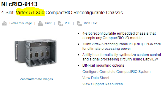
I'm trying to download the Xilinx tools 10.1 to use with a chassis 9113 in LV2011. Based on this white paper, that the compiler below should work perfectly. The problem is that I can't seem to download all the way.
I can't seem to cross ~ 336MB using the standard or the downloader OR. Any ideas? Does anyone else have this problem?
http://www.NI.com/download/LabVIEW-FPGA-Module-2013/4249/en/
Thank you
-PBD
Well well... on the good side of things, you don't want 10.1 anyway!
Virtex-5 LX50 FPGA<- requires xilinx="">
10.1 is only for devices FPGA Virtex-II! (.. .after LabVIEW 2009 it was, just for all of you who read this know).
so... try this link: http://www.ni.com/download/labview-fpga-module-2013/4248/en/
-
LabVIEW FPGA: Problem compiling look-up Table
Current versions of software:
LabVIEW 2014 SP1
LabVIEW FPGA 2014
Xilinx Vivado
I'm having a huge problem in trying to compile my LabVIEW FPGA code.
Some recall of the code:
It's all in a SCTL.
I am streaming in a FIFO DMA and comparing it with the values previously stored in the shift registers (which are initialized to 0 at the start of the loop) in the SCTL.
The results of the comparison are then piled into a U16 and loaded into a lookup table (I use the LUT - 1 d), and I'm so help this LUT to decide what value will be charged to travel to record for the next iteration of the loop, which, in any case, would be either the current values of the flow, or the post previous registry value.
(It's a triage loop)
I am able to run very well in simulation mode code, but when I try to compile, I get this error:
"The selected object has a built-in shift register that makes the output on a particular loop iteration correspond to the entries in the previous iteration."
Connect the outputs of the object directly to a minimum number of nodes of Feedback or uninitialized shift registers. You cannot connect the outputs to another object.
See using LabVIEW for more information on the objects with registers embedded offset. »
Someone at - it ideas why this happens, and what might be the possible solutions?
I'm tempted to break it down into separate loops, but I prefer not to because it is now a loop (and working in my simulation).
I found my problem.
Any time that a LUT is in a chain shift register, it cannot:
1. be part of a string of shift register that has a variable initialized
2. follow-up to no decisive structure, like a box structure.
I just moved the position of LUT and it works.
-
problems with the project of example LabVIEW FPGA
I'm trying to adapt the example project record on CompactRIO and LabVIEW FPGA Waveform Acquisition for my hardware, but can't seem to do things. I'm just following the instructions in the tutorial, but can not make sense out of section adapt this example to your hardware project, in particular, the instruction to "Drag FPGA Main.vi in the Project Explorer in the Open FPGA VI service window reference VI." Can someone explain on what is supposed to happen here? BTW, the target hardware that I'm doing this work on is a cRIO-9068 with some C series i/o modules.
Finally, I came across the answer. For anyone else who may encounter this problem, the attached screenshot is worth a thousand words.
-
Butterworth on Labview 8.6 FPGA filter problem
Hello
I was testing the filters of reconfigurable low-pass butterworth on FPGA found from the Finder of example (using Reconfigurable Butterworth filter - R - series.lvproj). This VI generates a sinusoidal signal and passes through a filter of Butterworth. When I put the filter low pass frequency to a low value (~ 2 Hz) and generate a sinusoidal signal of 0.5 Hz filttered out is not so much more (see figure). The filter is 2nd order, so this is a characteristic of the filter? And what do I do if I want a taste of high-frequency and use a low cutoff value?
v: * {behavior:url(#default#VML) ;}
O'Bryan: * {behavior:url(#default#VML) ;}
w\: * {behavior:url(#default#VML) ;}
. Shape {behavior:url(#default#VML) ;}Normal
0fake
fake
fakeMicrosoftInternetExplorer4
/ * Style definitions * /.
p.MsoNormal, li. MsoNormal, div. MsoNormal
{"mso-style-parent:" ";"}
margin: 0 cm;
margin-bottom: .0001pt;
MSO-pagination: widow-orphan;
font-size: 12.0pt;
do-family: "Times New Roman";
mso-fareast-font-family: 'Times New Roman' ;}
@page Section1
{size: 612.0pt 792.0pt;}
margin: 72.0pt 89.85pt 72.0pt 89.85pt.
MSO-header-margin: 35.45pt.
MSO-footer-margin: 35.45pt.
MSO-paper-source: 0 ;}
div. 1
{page: Section1 ;}}
--> I'm using Labview FPGA Module version 8.6 and PCI-7833R-map. LabVIEW 8.5, I remember that Butterworth filters, for above and below 2 kHz cutoff frequencies are actually different screws but on LV 8.6 they seem the same./ * Style definitions * /.
table. MsoNormalTable
{mso-style-name: "Table Normal";}
MSO-knew-rowband-size: 0;
MSO-knew-colband-size: 0;
MSO-style - noshow:yes;
"mso-style-parent:" ";" "
MSO-padding-alt: 0 cm 0 cm 5.4pt 5.4pt;
MSO-para-margin: 0 cm;
MSO-para-margin-bottom: .0001pt;
MSO-pagination: widow-orphan;
do-size: 10.0pt;
do-family: "Times New Roman";
MSO-ansi-language: #0400;
mso-fareast-language: #0400;
mso-bidi-language: #0400 ;}-Heikki
Hi Heikki,
The reconfigurable version (IE, with 'See the terminal configuration' checked) does not support the implementation of low-frequency modified. This is because we cannot change the filter architectures running. The nonreconfigurable version, however, must use the same implementation updated him you saw in LabVIEW 8.5 for the low cutoff frequencies, defined here as the frequencies less de.01 * sampling frequency.
Your example of 100 kech sampling rate. / s and 2 Hz cut-off is pretty extreme, even for the implementation changed. The usual technique for situations like this must be a smoothing downsampling at a rate that is better suited to the break you need. Rational resampling of the FPGA Math palette & analysis is designed for this purpose.
Kind regards
Jim
-
FPGA 2012 training: exercise fails '4-Wire Protocol' 7-2: not supported in single-cycle Timed loop
I work through the training courses OR 2012-FPGA with Labview 2014 SP1. I find the solution provided to exercise 7-2 called '4 son Protocol.lvproj' does not work. He is unable to run with the message "LabVIEW FPGA has reported the following error: item (s) not supported in single-cycle timed loop.»
Should it? I thought that the examples in the solutions folder were supposed to work such as provided. What needs to be fixed for this work? Thanks for any help.
Hello jbeale1,
It is a known problem. Here is the comment of NEITHER:
---------------
Exercise no. 7-2: 4 - Wire Protocol [Allen Hsu 2013.8.19]
- Description of the problem: exercise 7-2 uses a sine wave generator inside a SCTL VI. In 2012, LV, this VI is not supported in the SCTL, but LV 2012 will allow you to use mode 'simulation' (run on the dev machine). However, LabVIEW 2013 not even lets you use this VI in "simulation" mode If you run the VI with the sinusoidal generator inside a SCTL VI, LabVIEW 2013 gives you a "or objects not supported in single-cycle timed loop.
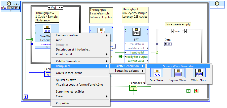
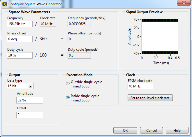
- Solution: If the students use LabVIEW 2013, you must tell the students to replace the sinusoidal generator inside the SCTL pre-built exercise VI VI with a Square Wave generator VI with the option "inside the SCTL" enabled in its configuration window, as shown below:
--------------
To replace the "sine wave generator" right-click on it and select the 'Square Wave Generator'. Then you have to double click on the "Square Wave Generator" and select "inside the only cycle timed Loop". You should then be able to run the example.
-
Simulate the sine wave using LabVIEW FPGA with NOR-myRIO and display in real time
Hello
I'm relatively new to LabVIEW FPGA. I am trying to test (and later apply) controllers high speed on myRIO.
At this point, I'm trying to simulate the sine wave from 1 to 10 kHz using Sinewave generator VI express. I also intend to display the sine wave on the time real (RT) using FIFO. However, I had a bit of trouble to understaing various synchronization parameters.
1. how to encode information about the sampling frequency generating sine wave? (The side FPGA vi requires only the frequency of the signal and possibly phase and does not rate update lines)
2. how to estimate the number of items in a FIFO? (that is, the relationship between the rate of updates to loop (RT), the signal frequency, sampling frequency and the number of items in the FIFO)
It would be great if we could share a very simple program (side host and target) that did something similar.
Thank you
MILIN
Milot,
I think the problem is the type of data in your FIFO. Your FIFO is configured to use a data type of I16. The problem is the number, it displays only ever will be-1, 0 or 1. To resolve this problem, you must send the sine wave as a fixed point data and convert it to a double on the side of the RT. This should significantly improve your resolution.
-
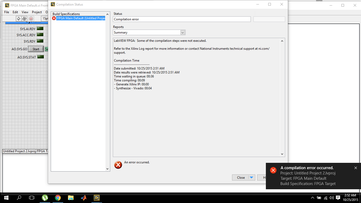
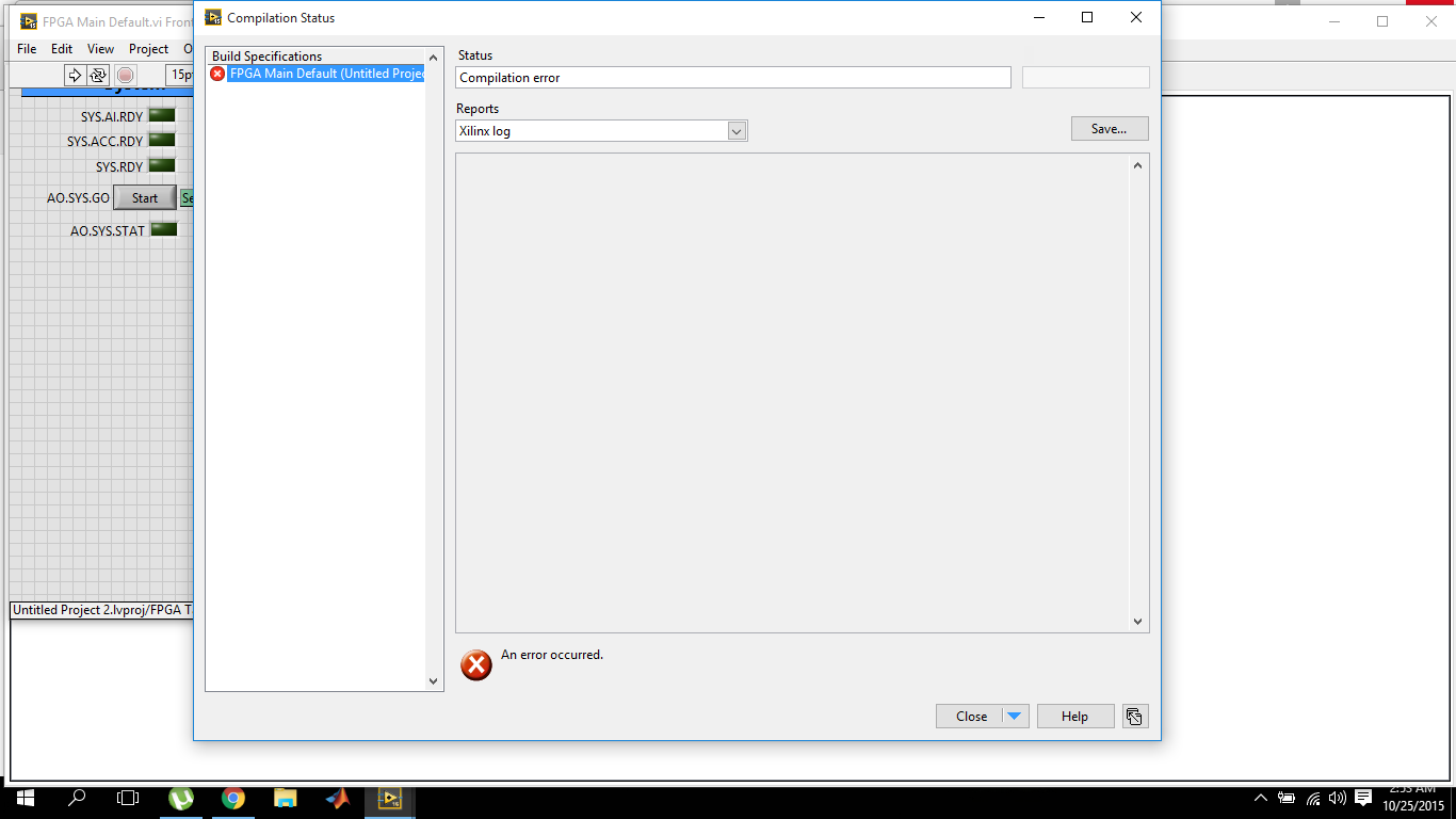
LabVIEW FPGA, 2015 compilation error
I've recently switched to LabVIEW 2015 and I'm working on OR myRIO. So also installed myRIO 2015 bundled software. The problem I have is that the compilation of fpga fails within 10 seconds.
and the target Xilinx journal report is empty
The first time when I tried to compile on 2015 version, it failed and the message box that failed came alongwith the avast antivirus warning for malicious activity. I reported it as wrong and now I tried several times with avast shield disabled control, but the results are the same. While the version of labVIEW 2014 works very well.
Now, I'm sure that there is something wrong with the installation of Vivado because this dll is part of it. The dll must be default in the2014_4\lib\win32.o directory C:\NIFPGA\programs\Vivado if you are using an operating system for 32-bit AND also in C:\NIFPGA\programs\Vivado2014_4\lib\win64.o If you use a 64-bit operating system. If the dll is not here, it is probably that the anti virus (I've never seen what happens to Xilinx but I have for other stuff).
I'm emphasizing the 2014_4 because LabVIEW 2015 uses Vivado 2014_4 while 2014 LabVIEW uses Vivado 2013_4. Since you have also installed LabVIEW 2014, you must have 2013_4 as well and if it works, you will find the dll I just wanted you make sure you check the correct directory for the Vivado 2014_4.
Download and install (reinstall or repair if already installed) 2015 LabVIEW FPGA Module Xilinx tools Vivado 2014.4. You can also use the DVD Setup if you have. It would be a good idea to do the installation with the disabled and even anti-virus try the first compilation the same. Try and let me know if the problem persists.
Kind regards
-
Internal software error of LabVIEW FPGA Module - 61499
I get the error next (in a pop-up window) in the phase of sompilation for the FPGA target with a vhdl IP. This error continues to occur even after restart LabVIEW and the PC. Someone at - it solved is this kind of problem before without having to re - install the software?
Here is the error information:
Error-61499 occurred at niFpgaXml_GetValue_String.vi<><><><>
Possible reasons:
LabVIEW FPGA: An internal software error in the LabVIEW FPGA Module has occurred. Please contact National Instruments technical support on ni.com/support.
Additional information: lack the tag required XML (/ CompileServerList)
As a first step, I can compile the vhdl IP node successfully. However, once when I'm running a VI with the FPGA, the bureau stop working. After that I restarted by force, it cannot perform the build of a vhdl IP node. Even without connecing to the jury of LabView, he pointed out errors before the end of the sompilation.
Interestingly, the screw which also includes nodes IP vhdl that I properly compiled before, I can still run the VI to the Commission and it works correctly.
Thank you
Looks like your ActiveJobsList somehow has been corrupted. I saw occur when computers are hard stop or blue screen during compilation. I don't have that LabVIEW 2014 installed on my machine, so your path will be a little different, and the file extension will be a .txt or .xml instead of .json, but try this:
Move the file "C:\Program Files (x 86) \National Instruments\LabVIEW 2014\vi.lib\rvi\CDR\niFpgaActiveJobList.json" (or your equivalent) out of the above directory (back it upward and delete essentially) and restart LabVIEW. Must regenerate the file and resolve the problem.
-
LabVIEW FPGA: Integration node clock wrong
Hello
I'm having some difficulties to understand how the clock is part of the node IP for LabVIEW FPGA and was hoping to get some advice.
What I try to do is to set up a digital logic circuit with a MUX feeding a parallel 8-bit shift register. I created the schema for this Xilinx ISE 12.4, put in place and can't seem to import the HDL code into an intellectual property node. When I run the VI, I am able to choose between the two entries for the MUX, load the output in the shift register, clearly the shift register and activate the CE.
My problem is that when I switch to the entrance of THIS, he should start 1 sec shift (Boolean true, SCR, High, what-have-you) in the registry once each clock period. Unfortunately, it instantly makes all 8 bits 1 s. I suspect it's a question of clock and here are some of the things I've tried:
-Specify the input clock while going through the process of configuring IP nodes.
-Adding an FPGA clock Constant as the timed loop.
-Remove the timed loop and just specifying the clock input (I'm not able to run the VI that I get an error that calls for a timed loop)
-Do not specify the clock to enter the Configuration of the IP node and wiring of the FPGA clock Constant to the clock input (I can't because the entry is generated as a Boolean).
-Remove an earlier version of the EC who had two entries up to a door and at ISE.
-Specify the CE in the process Configuration of the IP nodes.
-Not specify this in the process of setting up nodes IP and wiring it sperately.
-Various reconfigurations of the same thing that I don't remember.
I think I'm doing something wrong with the clock, and that's the problem I have. Previously, when I asked questions to the Board of Directors on the importation of ISE code in LabVIEW FPGA, a clock signal is not necessary and they advised me to just use a timed loop. Now, I need to use it but am unable to find an explanation online, as it is a node of intellectual property.
Any advice would be greatly appreciated, I'm working on a project that will require an understanding how to operate clocks the crux of intellectual property.
Thanks in advance,
Yusif Nurizade
P.S. I have attached my schematic ISE and the LabVIEW project with one of the incarnations of the VI. The site allow me to add as an attachment .vhd file, but if it would help I could just paste the body of the code VDHL so just let me know.
Hello Françoise,.
I spoke to the engineer OR this topic and it seems that it was sufficient to verify that your code works, by putting a wait function of 500 ms on the while loop to check that the registers responsible and clear. I'm glad that it worked very well!
-
LabVIEW FPGA: An internal software error in the LabVIEW FPGA Module has Unknown
Sir/Madam,
Note Labview 2012 SP1 installed about 2 weeks ago.,.
Accident occurred during the compilation of an fpga vi who worked satisfactorally in the past.
When I restarted and went to the message recomplile "LabVIEW FPGA: an internal software error in the LabVIEW FPGA Module" see attached picture of popup.
I reinstalled Labview in its entirety and backed out the changes I made to the vi but still get the same message.
Thanks in advance
Daryl
It turns out that the question was in the VI and not of LabView FPGA module as the message may indicate. I created a vacuum vi, cut and pasted items in this from the vi error and recompiled and it ran very well.
Somehow the vi has been corrupted internally.
Thank you it's fixed.
-
Error when create control LabVIEW FPGA CompactRIO
I have error when you try to create a new model of LabVIEW FPGA CompactRIO control project. I tried with LabVIEW 2014 and 2014 SP1 update. This error always occurs.
Please help me with this.
Kind regards
Thang Nguyen
Hello
I fix the problem by removing LabVIEW 2014 SP1 and reinstall again. After the reinstallation of LabVIEW, I create the project template.
Kind regards
-
When I compile a labview fpga VI, (my version of labview fpga is 2014), I get the not found error Xilinx 10.1 build tools.
But for 2014 labview, version 14.7 Xilinx is the only compatible and that I installed. But it is still asking for Xilinx version 10.1. I tried both with configured CompactRIO and also a vi without hardware. The same is repeated each time.
What can be the problem? Please help me.
Elodie
What FPGA target do you use? I think for Virtex 2 target Xilinx 10.1 tools are used.
-
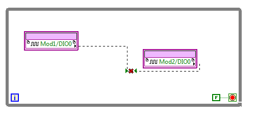
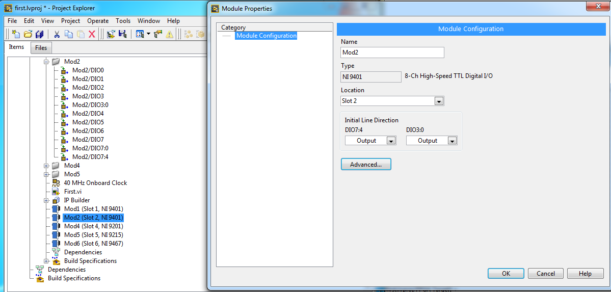
Configuration of the inputs/outputs of NI9401 in labview FPGA
Hello
I am very new to Labview FPGA. In fact, I'm implementing the very first example introduced by OR for learning Labview FPGA. I need to connect an entry of a NI9401 on one exit from the other.
However, when I drag and drop the input/output units, the two act as inputs:
I also changed the propties one of the NI9401 to act as output. But the problem persists.
It is the example that I am building.
I'd appreciate any suggestions.
https://www.YouTube.com/watch?v=mv112V-P030&index=1&list=PLbCk9hRe-ziECXQjE--fN29C_kcx7CHnA
Right-click on the output node, and then select "change to write."
Maybe you are looking for
-
I created a Skype account. I tried a disconnect then you connect using my Facebook account. According to the online instructions, I should have been asked to merge my Facebook account with the Skype account... but I did not receive this prompt. How c
-
E280 v2 - My MTP does not work. Please help me.
I got the Sansa since 11/07. I was wrong before, but this is the most frustrating problem to date. Two weeks ago the device quit afford toansfer audio books (via the Overdrive Media Console - WMA software - draws) from my laptop to the device. It
-
Error message "unable to connect to the proxy server.
I use Google ChRome as my browser. Unable to connect to the Internet. Error message "unable to connect to the proxy server. I went to the settings and tried to change the proxy settings. When I uncheck the box "use a proxy server" it does not apply o
-
Example of BrowserFieldDemo (OS 4.5) using the connection Https does not redirect events
-
Samsung SCX-4100 does not print on the computer Windows 7 x 64
I have a Samsung SCX-4100 printer. It worked fine on two different computers of precedents, one with Vista and the other running Windows 7 (x 32). I updated to Windows 7 Professional 64 - bit and charge computer driver Samsung x 64. The printer ap