Sampling frequency of NI9234 - LabVIEW FPGA
Hey guys,.
I have a very simple question. I'm a code example in examples of labview seeking NI 9234. What is the difference between the flow of data and samples by channels?
If we read with maximum data rate which is 51.2 kech. / s (4 channel playback), the samples per channel must 51.2/4=12.8 kech. / s per lane. Am I wrong? If this is correct, what is the sample by channel control in the FPGA vi?
The rate is how many times we take a sample of a/d. The number of samples is how these samples, you return to the program. By example, if you had a rate of 1000 samples per second you can ask 500 samples which would take 500 ms to acquire. At a rate of 2000 samples/s, asking 500 samples would take half as long. Keep the same 2000 samples/s and ask for samples of 2000, back to 500 ms to acquire.
Tags: NI Software
Similar Questions
-
How to measure the frequency of sampling (s/s) in LabView FPGA?
Hello
I am trying to find a way to measure the sampling frequency (s/s) during which I read from analog input in LabVIEW FPGA. I know that the sampling frequency is specified in the data sheet of the module HAVE, but I want to measure in LabVIEW.
Any suggestions?
A screenshot of the example code would be greatly appreciated
Hey phg,.
If you have some time loopand in this loop, you export a sample by iteration of loop via an I/O node. You can't out two samples on the same I/O node within an iteration, it's always one!
So if your loop takes 1 second to run you have a sampling rate of 1 Hz output. The same goes for sampling of entry. How long your loop takes to run can be calculated as explained above.
Samplerate [s / s] = 1 / [s] while loop
-
Different sampling rate with the same connector AIO, Labview FPGA
Hello
I use LV 2009 with the new Toolbox FPGA and an NI PXI 7854R. I acquire an analog signal with a sampling frequency of 600kS / s. I need as the sampling rate for the processing of the data, but I also need the signal sampled with a much smaller, variable sampling frequency to a FFT.
I've attached a picture to clarify, in a simple example, I'm looking for.
I tried with the structure case only take each ' iht iteration, but did not get the expected results.
Does anyone have another idea how to solve my problem? Of the, "Resampling" express VI in the funtion FPGA palette does not help me.
Thanks in advance,
Concerning
Hello
the connector for the analog input is a "shared resource", so you should he alone in your FPGA Code.
Find attached an example that shows how to perform this task of analysis.
Concerning
Ulrich
AE OR-CER
-
Simulate the sine wave using LabVIEW FPGA with NOR-myRIO and display in real time
Hello
I'm relatively new to LabVIEW FPGA. I am trying to test (and later apply) controllers high speed on myRIO.
At this point, I'm trying to simulate the sine wave from 1 to 10 kHz using Sinewave generator VI express. I also intend to display the sine wave on the time real (RT) using FIFO. However, I had a bit of trouble to understaing various synchronization parameters.
1. how to encode information about the sampling frequency generating sine wave? (The side FPGA vi requires only the frequency of the signal and possibly phase and does not rate update lines)
2. how to estimate the number of items in a FIFO? (that is, the relationship between the rate of updates to loop (RT), the signal frequency, sampling frequency and the number of items in the FIFO)
It would be great if we could share a very simple program (side host and target) that did something similar.
Thank you
MILIN
Milot,
I think the problem is the type of data in your FIFO. Your FIFO is configured to use a data type of I16. The problem is the number, it displays only ever will be-1, 0 or 1. To resolve this problem, you must send the sine wave as a fixed point data and convert it to a double on the side of the RT. This should significantly improve your resolution.
-
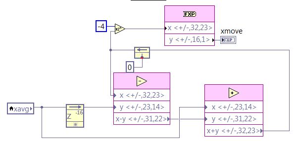
I created a Labview FPGA .vi using a structure flat sequence that shows the output of a sensor at a sampling frequency of 1 kHz on a digital SPI. After reading, I write the point data fixed in a FIFO, which is read by a host vi and finally written on the hard disk for post-processing. I need to add logic for the calculation of the average for the further process the signal FPGA vi. I want to continue at the exit of the original 1 kHz sampled datat to the FIFO, but also perform a sprawl on the steps and write these results at the same frequency of 1 kHz to the FIFO. The average feature, I would like to implement is a two-step process. Step 1 is to take samples of 1 kHz and perform an average of 16 samples based frame. In other words, I want samples of sum 16 1 kHz and dividing by 16 and decimate 16:1, which produces data of 62.5 Hz. Step 2 is to take 62.5 Hz sampled data and perform a moving average of 16 samples on these data and output resulting at the same sample rate of 62.5 Hz. I want these 62.5 Hz sampled data to be injected into the FIFA as well as the original data of 1 kHz sampled (unmodified) at the frequency of 1 kHz.
I've got step 1 work correctly using the block "mean, Variance, StdDev FPGA vi" with number of samples on 16. This block runs within a sequence of flat sequence structure after I received each sample 1 kHz on the SPI. My fight is the average feature mobile step 2. I try to use the code in the screenshot below, but am unclear regarding how/where to implement this logic inside is my structure flat separate sequence while loop, structure of the case, etc, in order to ensure that it only works on one of 62.5 Hz samples to this flow of data at once. I tried to put it inside the sequence that executes the block average and further in a case that is driven by the Boolean "valid" the average block output. I obviously don't understand how these different loops run, because it does not work properly. Can someone tell me how to implement the logic of moving average in my vi FPGA existing to produce the desired results as described above? Screenshot below of the logic (step 2) average mobile I am trying to use. In addition, find attached my screws vi FPGA that I need help with is 'CA215_SPI.vi' and the level vi host is 'Host.vi '. Thanks in advance.
Joel
This question is closed. I realized that my approach to implementation was actually working. I just had a stupid mistake on my fixed point output bit size, giving me results errenous.
-
How to acquire the signal to very high sampling frequency
Hello world
My name is Luke Ho. I am trying to acquire the signal with Labview (Sthelescope). The signal comes from sensor acoustics, then filters and amplifiers to adapt to ADC rank (0 - 5V). Thus, the maximum frequency of the signal is 40 kHz.
According to the Nyquist theorem, I sampled at least 80 Khz signal.
Is there a sampling frequency devices like that? or y at - it another way of better? I used the Arduino before, but it was about 10 kHz.
I need your advice.
Thank you all and have a nice day.holucbme wrote:
Thanks for your recommendation
But is it possible without USB Data Acquisition, it is quite expensive for me.
This is the cheapest option to NEITHER. I tried to look for options to other companies, but more I found in the same price range, or not answering is not your condition of sample rate.
-
AI PXI-6255 sampling frequency
Hello
We use a simulated PXI-6255 device and with the LabVIEW example, apparently, that we can achieve a sampling rate of 20 kHz to 50 channels without warnings or errors.
The spec is the number max of 20 kHz channels must be approximately 38 channels (750000 / 20000).
1.25 single channel of MECH. / s
multi-channel of 750 ksps / s (aggregation)
The simulation cannot not representative of the unit or the real PXI-6255 does support a higher rate that we expect?
Hi jharris66,
It is not a limitation of the driver to the sampling frequency, so a simulated device reports any error in this case.
In this example, I think that the limit of 750 kHz comes to the multiplexer. I don't expect to see the same error messages with the real device, but your accuracy will probably not to spec because not allowing enough time settling between the channels.
The limit of 1.25 MHz is the maximum ADC sampling frequency. You can probably exceed this number somewhat, but once you go too far beyond 1.25 MHz you will eventually receive a synchronization from the hardware error when the ADC cannot follow.
Thus, the specification is still technically 750 kHz for channels multiple acquisitions. You can probably run at a higher rate than this (even on real hardware), but I wouldn't say that it is supported.
Best regards
-
limited on PCI-6052E sampling frequency
I'm trying to measure with two channels with a PC containing a NI PCI-6052E card that is capable of 333KS/s on LabView 8.2. With two channels each channel must be able to 333KS/s / 2 = 166.5KS / s. everytime I try to set the sampling frequency above 94339 Hz I the following warning and the vi no longer works.
WARNING 200012 occurred DAQmx start Task.vi:1
Possible reasons:
Clock speed specified is greater than the maximum ADC conversion rate. ADC invaded errors are likely.If I place a similar task in the Measument and Automation Explorer and I can easily make two channels measures to 160kHz without error. Above 166kHz I start getting the same caveat (200012). The code that I use calls first DAQmx create Channel.vi, then DAQmx Timing.vi and finally DAQmx start Task.vi. Everything works fine and I did measuements, but I can't rise above 94339 Hz sampling rate even if it should be possible.
I just looked and I can't understand the issue here.
Dear Voyn,
I thank very you much for your message on our forum. If you create a task for a single channel, you can get a higher sampling rate? Are you able to reproduce the same problem with an example from the finder example? Go to hardware to go end tab selected and output-DAQmx online-online-online-online Acq Cont voltage analog measures & chart voltage-Int Clk.vi
You can select several channels as well. If it shows the same behavior; which driver DAQmx do you use?
Best regards
-
How to specify the sampling frequency? Must use "measurement & Automation Explorer '?
I use to measure the input current analog OR cDAQ-9171 (chassis only location USB) and NOR-9207. I have 2010 NOR-installed DAQmx and LabVIEW.
How can I specify the sampling frequency?
If I use M & A Explorer to create the task, I can specify the flow rate (Hz) on the Configuration tab-> sync settings.
For the acquisition of data NOR, it is mandatory to use M & A exploring?
If I don't want to use M & A Explorer, how can I specify the rate (Hz)?
Hello
You can specify the sampling frequency with "DAQmx Timing.vi" located in the function palette DAQmx (read context-sensitive help on how to use wisely).
You do not have to use M & A exploring (MAX) to create a task.
A simple and quick way is to use DAQ Assistant (same configuration as in MAX) to configure your measurement.
Another is to use blocks of DAQmx function to manually build your application code.
In my experience Assistant DAQ is ideal for simple tasks (one measure), with regard to the more complex measures (synchronized the analog and digital inputs).
I tend to use function blocks because they give you more freedom about code execution.
Note: You can also build DAQmx code from a wizard configured DAQ task.
Best regards
Matej
-
Synchronization of the inputs and outputs with different sampling frequencies
I'm relatively new to LabView. I have a NOR-myDAQ, and I am trying to accomplish the following:
Square wave output 10 kHz, duty cycle 50%.
Input sampling frequency of 200 kHz, synchronized with the output that I get 20 analog input samples by square wave, and I know what samples align with the high and low output of my square wave.
So far, I used a counter to create the square wave of 10 kHz, display on a digital output line. I tried to pull the document according to (http://www.ni.com/white-paper/4322/en), but I'm not sure how sample at a different rate than my clock pulse. It seems that this example is intended rather to taste one entry by analog clock pulse. There may be a way to create a faster clock (200 kHz) in the software and use that to synchronize the analog input collection as well as a slower 10 kHz output generation square wave?
I eventually have to use the analog inputs to obtain data and an analog output to write the data channel, so I need the impetus of the square wave at the exit on a digital PIN.
How could anyone do this in LabView?
Hi Eric,.
All subsystems (, AO, CTR) derive from the STC3 clocks so they don't drift, but in order to align your sample clock HAVE with pulse train that you generate on the counter, you'll want to trigger a task out of the other. I would like to start by a few examples taken from the example Finder > Input and Output material > DAQmx. You can trigger GOT off the train of impulses, start by Gen digital Pulse Train-keep -you probably already use a VI like this to generate 10 k pulse train. AI, start with an example like Acq Cont & chart voltage-Ext Clk - Dig Start.vi-you'll want to use the internal clock so just remove the control of the "Source of the clock" and it uses the internal clock. From there, simply set the "Source of the command" either be the PFI line generates the meter, or ' /
/Ctr0InternalOutput '-assuming that you are using the counter 0. You'll want to make sure that the start of the task HAVE faced the task of counter I is ready to trigger off the first impulse. They should be aligned at this point. For debugging, you can use DAQmx export Signal to export the sample clock - you can then brought the train line and the PFI pulse to make sure that they are aligned.
Hope this helps,
Andrew S
-
Dear all!
I hope everyone is doing well!
Well! I am a student in first year of Labview and would like an expert on this VI opinion I did. I'm learning by doing! This VI is to see the effects of sampling at different frequency. I have a LABVIEW 8.5 and uses an express VI to simulate signal, two assistant screws DAQ etc. I also play a little with the number of samples and sampling frequency.
Come to the points that I did not understand!
1. the present VI crashes and I am not able to understand what is the reason?
2. the time scale itself changes as I raise the number of samples, even if I keep the same frequency sampling.
3. in addition, the peak frequency changes with the number of samples! Why?
I hope to have your kind response!
Thanks for your time!
Tajim
Hi Tajim,
Sorry for the late reply. I made a few changes to your VI and it works very well.
You can start with the choice of the same sample rate and the number of samples of the three waveforms. In this way, all will synchronize initially.
After that, you can try to change the sampling rate and the number of samples for the waveforms. However, you should becarefull when setting very large number of samples. If you have a low sampling rate, say 100 Hz and a high number of samples, say 1000 samples it will take 10 sec to acquire all the samples. If the second DAQ assistant is running at the highest sampling at the same time, you will have an overflow of buffer of data acquisition and it may hang. Of course it is a means to avoid this by implementing different structures in LV, but for the purposes of this test, you should be ok if you just keep this in mind.
Thank you!
-
sampling frequency global myRIO
Hi Forums,
Small question, the sampling frequency of myRIO HAVE is 500kS/s aggregate on the MXP connectors (A and B).
My current thoughts are connected to AI0 - AI3 entries on connector MXP has, give me 125kS/s through, so ~ 62.5 kHz of bandwidth (please, correct me if I'm wrong).
What I'm working, is if the split of gets 500kS/s between total entries shared between A & MXP B; MXP What is total 500kS/s per connector? That is, if I shared my entries to AI0 - AI1 on MXP has; and AI0 - AI1 on MXP B, I would be able to increase my rate of sampling per channel?
Kind thanks,
Tori
Hey Tori.
Here's a thread on a similar question: http://forums.ni.com/t5/Academic-Hardware-Products-ELVIS/Question-about-myRio-Hardware-ADC-DAC/td-p/...
All I think my reply in this thread (copied below) should answer your question:
The best way to think about the material of myRIO is as if it has two ports, the MSP and MXP (do not distinguish between A and B on the MXP connectors).
The MSP's HAVE MXP and Audio In (IE all HAVE him) share the same Active Directory Connector.
The MSP AO and Audio Out each have their own DAC but share a line of SPI.
AO MXP has its own DAC and has his own line of SPI
Let us know if you have any other questions!
-Sam K
Join us / follow theGroup of pirates of LabVIEW on google +
-
Any problem of loop sampling frequency
Hello
I am a student who did a thesis on the electric vehicle tracking system in labview. I collection of usb-6009 analog measurement data, transfer it in the daq assistant and state machine inside a while loop to do the follow-up process.
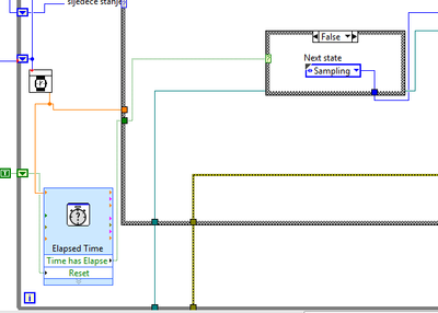
So, I have a State that determines the sampling frequency of the loop cycle, and I was able to modify this rate in the values of 0.1, 1 to 5 Hz, I realized that it with out of time VI Express, which is in a loop, but outside the case of structure for States. I'm going to rate last in time "Target Time" of entry and the Boolean output "Elapsed time" goes to the business structure, passing to the next state when the time runs out. In the next State, it resets the elapsed time and the cycle starts from the beginning.
Thus, everything works fine until I see in my log file (txt file where I save the measured values) it's only 3 or maximum 5 Hz frequency 4 samples per second.
I have a good enough computer with processor i7 and 8 GB of ram.
What could be the problem?
In the picture below it can be seen how I realized that with timer.
Thank you in advance.
Matej
As I mentioned in my previous note, your problem is that you start a new target for the time time vi ONCE your analog playback is completed. This ADDS essentially no matter what time is taken by Analog playback on top the time you ask vi of time spent waiting.
I modified your vi and I think that should take care of your problem of synchronization.
However, I suggest using "Wait until the next ms Multiple" because unlike the vi express you are using, one I mentioned allows other processes are doing their job in the meantime.
Hope that helps...
-DP
-
If the butterworth filter available in LabVIEW FPGA is cascade, can I get a higher order filter?
I need a 10th order filter lowpass butterworth with cut-off frequency 5 kHz. Can I build by 4th cascading of 2 order butterworth filters and 1 2nd order available in LabVIEW FPGA each filter in butterworth with cut-off frequency 5 kHz?
This will increase the amount that your data will be filtered but will not increase the order in the Manor that you think. If you cascade two 2 4th order filters and compare that results to a filter of order 8, the resulting field filter cascading bode would look more like a 6,5e order filter.
Logan H
-
Use of FIFO memory on two areas of clock (Labview FPGA) block
Greetings!
I'm developing an application on the FPGA of the vector signal OR 5644R
transmitter/receiver. I have two loops single-cycle timed: a 40 MHz making a convolution
and writing a FIFO memory block and the second at 120 MHz (sample clock)
who reads from block FIFO memory and uses the following values
interpolation...Under what circumstances is it permissible to use a FIFO memory block to transfer
values of a loop from 40 MHz to a loop of 120 MHz (sample clock)?
The reason I ask the question, it is that the compilation of my code repeatedly of not
reported the error below:ERROR: HDLCompiler:69 - "/ opt/apps/NIFPGA/jobs/J9k7Gwc_WXxzSVD/Interface.vhd" line 193:
is not declared. I share for everyone's reference, screenshots of my code which is an extension of
sample 'Project streaming VST' given in NI5644R. A brief description of attachments is
given below...
1. "Top_level_FPGA_part1_modification.png": in a loop SCTL 120 MHz, a sub - vi bed FPGA
go a block FIFO memory... In fact, the reading is actually made when entry
"read_stream" is activated... (see details in read_from_fifo_true_case.png)
2. "Top_level_FPGA_part2_modification.png": a 40 MHz SCTL, wherein is a subvi FPGA
called to write the output of convolution to block FIFO memory.
3. "target_respone_fpga_block_FIFO_modification.png": an output of a convolution filter is
written in block FIFO memory each time that the convolution output is available...
'ReadBlockFIFO' VI (circled in Top_level_FPGA_part1) is invoked in a 120 MHz SCTL.
4. "read_from_fifo_false_case.png": when the input "read_stream' of this vi is false,
data transfer memory FIFO of block to a different FIFO ('generation filter") takes
place.
5. "read_from_fifo_true_case.png": when the "read_stream' is set to true, the data is read in
'Filter generation' FIFO and spent on the chain of later interpolation to the
120 MHz SCTL...
I hope that the attachments give enough clarity to what I'm doing... If we need
For more information, do not hesitate to ask...
Kind regards
S. Raja Kumar
Greetings!
I think I understand the problem... The error probably occurs because a DMA FIFO
(FPGA host) is playing at 40 MHz, and it is checked for the number of items in a loop
120 MHz... It is not captured by the "pre-processing" by the labview FPGA, but by the Xilinx
compilation phase synthesis tool.
A lesson I share, is that if you observe this kind of problem, watch if there is incompatibility
in the areas of the clock to access a FIFO...
Kind regards
S. Raja Kumar

Maybe you are looking for
-
Cannot activate icloud library
When I try to activate the icloud on my itunes music library by following the steps: itunes - general preferences, it is not a "icloud library" option to check or turn on. Why can't I see this option?
-
Lost card SIM of Vibe X 2 support
Hello My vibe x 2 sim card tray was lost while I'm travelling. How can I get this part alone. Y at - it all optton to buy online or can I replace from the service center. Also, please provide the centre for smartphone lenovo in trivandrum, kerala Kin
-
6509 PXI and SCB 100 Port 0 and 3 Port have lines that are high
Hello I work with a PXI-6509 connected to an SCB-100. When I run the test panels lines 0,1,2 are high on port 0. 0,1,2,3 lines are high on port 3. I have a voltage of 3 volts measured between Port0 line 0 and Gnd (PIN 47 and PIN 50). Nothing is co
-
Windows 7 does not see SATA drive
I just upgraded from Windows XP to Windows 7 and now cannot access the SATA drive that I use for storage. I desperately need help to access this drive. Any help will be appreciated. I've seen suggestions on the use of upgrade instead of the custom in
-
JEG fik virus pa min pc og da den blev Lee midstede jeg and program som jeg ligger til dishwasher forskelige spout collage kuhu finder jeg det igen fulgte med min printer da jeg kobte den mine billeder forsvandt is men dem har jeg pa apperat Hilsen e