AI PXI-6255 sampling frequency
Hello
We use a simulated PXI-6255 device and with the LabVIEW example, apparently, that we can achieve a sampling rate of 20 kHz to 50 channels without warnings or errors.
The spec is the number max of 20 kHz channels must be approximately 38 channels (750000 / 20000).
1.25 single channel of MECH. / s |
The simulation cannot not representative of the unit or the real PXI-6255 does support a higher rate that we expect?
Hi jharris66,
It is not a limitation of the driver to the sampling frequency, so a simulated device reports any error in this case.
In this example, I think that the limit of 750 kHz comes to the multiplexer. I don't expect to see the same error messages with the real device, but your accuracy will probably not to spec because not allowing enough time settling between the channels.
The limit of 1.25 MHz is the maximum ADC sampling frequency. You can probably exceed this number somewhat, but once you go too far beyond 1.25 MHz you will eventually receive a synchronization from the hardware error when the ADC cannot follow.
Thus, the specification is still technically 750 kHz for channels multiple acquisitions. You can probably run at a higher rate than this (even on real hardware), but I wouldn't say that it is supported.
Best regards
Tags: NI Hardware
Similar Questions
-
How to acquire with NiScope at different sampling frequencies and lengths Records?
I need to acquire the data of 2 channels of the NI PXI-5114 map two different sampling frequencies high, at the same time. Also, I put 2 different record length. Is this possible?
I understand that 'Vertical' settings can be configured for individual chains because the function 'Vertical niScope Configure' has 'channels of entry with which we can assign the desired channel. But for horizontal settings such as "min sampling rate" and the record min length, I could not find such an option to specify the channel. Would it not common to both channels?
I hope that the device is capable of simultaneous sampling and therefore channels can be configured individually to different sampling rate.
Hi AJ_CS,
Why do you have to be distinct from sampling frequencies on channels separated from the digitizer even? What different sampling rate do you want?
But for horizontal settings such as "min sampling rate" and the record min length, I could not find such an option to specify the channel. Would it not common to both channels?
You do not have an option to configure the settings of hoirizontal on a channel by channel basis because this concept does not exist in the traditional sense of the use of a scope. Compatible with the concept of IVI, an oscilloscope traditional benchtop will have only a button or a set of buttons for setting the parameters of synchronization of the unit. There is therefore no horizontal configuration to separate channels on the scanners NOR.
I hope that the device is capable of simultaneous sampling and therefore channels can be configured individually to different sampling rate.
Similar to a traditional benchtop oscilloscpe, the device is capable of simultaneous sampling. But as mentioned above, the channels can not be configured for different sampling frequencies high.
However, you can ignore data that you think is not relevant. For example, if you assign 100MS/s CH0 and CH1 to 50 MS/s, then you throw all other samples.
Alternatively, you can use separate scanners (a channel on each digitizer) and configure them to taste at different rates. You can set frequencies of sampling on scanners NOR separated and even synchronize them with TClk.
-Andrew
-
PXI-6133 Pulse frequency output and input with DAQmx
I am trying to set a pulse meter output frequency task and read this signal with a frequency counter input task input pulses. I use a 2 PXI-6133, each connected to a BNC-2090 case has. I want to output a square of a certain frequency with the task frequency meter pulse output and then read the frequency of this signal using a task of cost input frequency. I don't know how to property set up these tasks, or how to define which device to use for each heap. I don't know what terminals on the BNC-2090 is the counter of entry/sortient channels correspond to them because that is not displayed in the documentation of the PXI-6133 or documentation of BNC-2090.
Please see the attached VI for my attempt to put this in place. Currently, I get two errors:
(1) error-200452 took place at the property Node DAQmx channel meter Test - referred to as property is not supported by the device or is not applicable to the task.
2. the error-89136 at DAQmx Start Task - specified route cannot be met because the hardware does not support.
If I remove two channels of property DAQmx where I try to put the terminals for the counters, while the program is running, but then I know not what terminals on the BNC-2090 meters are connected to! This causes the DAQmx read for the cost in the tasks of frequency to timeout because it does not detect a signal.
I would really appreciate the help to properly configure these tasks and determine what terminals on the BNC-2090 case has the task of counter will work on.
I see a few problems in the code originally:
- For your CI task, you type is defined as a counter entry > frequency. But on the node property of DAQmx channel for this task, you modify the CI. Property of PulseWidth.Term. It should be CI. Freq.Term. set the entry regardless of the PFI line you do not want the input signal on. Tip: you don't have to type the name of the device in at all. Enter "PFI0", it's the same as "DevN/PFI0" since the unit has already been specified in the DAQmx Virtual Channel Create function. The name of the device, leaving aside will make your code more flexible where you decide later to change the name of the device.
- Maps of the S series, such as the 6133, do not have the same flexibility to change the output terminals of tasks of meter you might find with M or X series device. Page 83 of the S series manual watch what signals can be extracted to PFI lines - Ctr0Out is not one of these. Instead, Ctr0 out is, by default, pin 2. Cabling to a BNC-2090 6133 is certainly difficult to understand out (probably because the 2090 was designed to work with the materials of the E and M series), but if you compare the pinout of a PXI-6255 0 with the 6133 pinout connector, you will notice that they are essentially a match 1-1. Pin 2 is PFI12 on the 6255, so I assume the same for the 6133. All this to say, Ctr0Out always appears on the pin 2/PFI12 for the 6133 and you therefore cannot change the output terminal that your code is trying to do, having for result error-89136. Remove this node from the property altogether and the error should disappear.
-
Xincrement is not agree with sampling frequency
I use two PXI-5114 scanners that are being synchronized. I am taking 5 seconds worth of data. I have = 1e3 sample rate and record length = 5e3. I get only about 1.3 seconds worth of data. I looked at the actual length of the record and the actual sampling frequency outputs and they said the same thing as the façade made. I looked at and then the info out of the Cluster.vi of Fetch NiScope Multi Wfm and he had the same record length, but the value of Xincrement is 262e-6. This fits with what I get. Any ideas?
Thanks in advance.
Hi AT1,.
Thanks for posting. What you see, this due to the fact that the minimum sampling rate of the PXI-5114 is 3.81 kech. / s. The digitizer will force any value less than 3.81 kech. / s up to this value, so a record of 5000 samples take 1.31 seconds to acquire. If you are looking to acquire 5 seconds worth of data, I recommend to increase the length of record about 19 050 samples, which should be about 5 seconds worth of data. Let me know if this would work for your application.
Kind regards
Joe S.
-
6255 sampling rate causes the dc offset
I see a dc offset in the measures of analog input I select different sampling frequencies.
I have USB-6255 (mass termination) multifunction data acquisition and I use measurement and Automation Explorer to put in place my entries.
My raw analog input is-0, 6250 volts dc, I have set up a task that uses 4 differential channels with no custom scale.
I have defined the scope of the input signal to +/-0 .8v for you sure I get good resolution.
Acquisition mode is continuous, samples of read is 1 k and I play with the order of 10kS/s rates 50kS/s.
While this task runs in the MAX, I can put my cursor in the rate field and use the top and down arrow keys to change the sampling frequency. As I do, I can see the light changes reported as much as 150 MV rate from one to the other.
It is a significant change when the total time of entry is lower to +/-1v.
The direction of movement is independent of the increase or decrease of the sampling frequency.
For example,.
23kS/s, the declared value is - 0.540v,
24kS/s, she moves to-0.620v.
25kS/s, she moves to-0.690v.
26kS/s, she moves back to-0665v.
27kS/s, she moves back to-0.625v.
and 28kS/s, she moves to - 0.535v.
At first, I thought that the sampling change made a change of the input impedance and change the load on my source, however, all the time, my dc signal source remained at the - 0.625v (as measured with a multimeter fluke at the connection point to data acquisition).
Why this is happening and what can I do about it? I want to give my users the ability to choose their desired sampling frequency.
My guess is that I need to add an amplifier to fixed gain with a gain of 5 to 10 to make the input signal to use the maximum of the analog input level (+ / 10v).
I use MAX version 5.0.0f1
Thanks for any help,
Tobin
Hi Tobin,
What do you use to generate the signal-. 625 volt? If you are using a switching power supply, you can experience aliasing where the power supply is turned on and stop.
In addition, are see you the same tensions at the same sampling rate? See you always - .540v to 23kS/s or vary over time?
Finally, you have a second 6255 you can try to replicate this on? It could be that the unit is defective.
N
-
The PXI - 6259 sampling rate M SERIES DAQ
Good afternoon friends,
I'm reading my series M manual trying to find AO maximum sampling rate I can run my PXI-6259 to. I need to generate four-channel (A0:3) grid output wave high fidelity. Higher sampling frequencies enable higher frequency in tone generation and a better representation of the sounds of broadband as white noise. How fast can I run this puppy, and is there a point where performance and reliability starts to suffer?
I'll keep digging for answers!
Thank you
Zach
Zach Hey!
If you look on page 3 of the 625 x card product, the analog output with 4 channels update is 1.25 MECH. / s. Rock on!
-
How to acquire the signal to very high sampling frequency
Hello world
My name is Luke Ho. I am trying to acquire the signal with Labview (Sthelescope). The signal comes from sensor acoustics, then filters and amplifiers to adapt to ADC rank (0 - 5V). Thus, the maximum frequency of the signal is 40 kHz.
According to the Nyquist theorem, I sampled at least 80 Khz signal.
Is there a sampling frequency devices like that? or y at - it another way of better? I used the Arduino before, but it was about 10 kHz.
I need your advice.
Thank you all and have a nice day.holucbme wrote:
Thanks for your recommendation
But is it possible without USB Data Acquisition, it is quite expensive for me.
This is the cheapest option to NEITHER. I tried to look for options to other companies, but more I found in the same price range, or not answering is not your condition of sample rate.
-
limited on PCI-6052E sampling frequency
I'm trying to measure with two channels with a PC containing a NI PCI-6052E card that is capable of 333KS/s on LabView 8.2. With two channels each channel must be able to 333KS/s / 2 = 166.5KS / s. everytime I try to set the sampling frequency above 94339 Hz I the following warning and the vi no longer works.
WARNING 200012 occurred DAQmx start Task.vi:1
Possible reasons:
Clock speed specified is greater than the maximum ADC conversion rate. ADC invaded errors are likely.If I place a similar task in the Measument and Automation Explorer and I can easily make two channels measures to 160kHz without error. Above 166kHz I start getting the same caveat (200012). The code that I use calls first DAQmx create Channel.vi, then DAQmx Timing.vi and finally DAQmx start Task.vi. Everything works fine and I did measuements, but I can't rise above 94339 Hz sampling rate even if it should be possible.
I just looked and I can't understand the issue here.
Dear Voyn,
I thank very you much for your message on our forum. If you create a task for a single channel, you can get a higher sampling rate? Are you able to reproduce the same problem with an example from the finder example? Go to hardware to go end tab selected and output-DAQmx online-online-online-online Acq Cont voltage analog measures & chart voltage-Int Clk.vi
You can select several channels as well. If it shows the same behavior; which driver DAQmx do you use?
Best regards
-
How to change the DAQmx sampling frequency
Hello
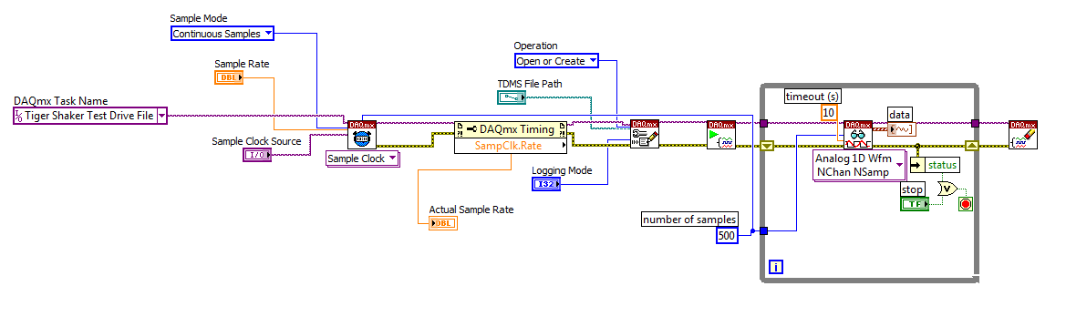
I'm trying to: record streaming channels (acceleration 21 and 1 tension) using a DAQmx task, then convert the data to a PDM file. The program files and output to the TDMS file very well. The issue I'm having is that I can't change the sampling frequency. I want to record 500samples/s and I can not get the "real sampling rate" of change of 1651.61samples / s. I am trying to use the clock to do this and I succumbed. I also tried to change the settings of "Timing" in the task without a bit of luck. Here is a screenshot of the .VI I created. I've also attached a copy of the file VI. Any help would be greatly appreciated!
Thank you
Tony
You will need to provide the model of your device. You can also look in the sheet/manual to see what the real supported sampling rates. Some devices have limited rates.
-
How to specify the sampling frequency? Must use "measurement & Automation Explorer '?
I use to measure the input current analog OR cDAQ-9171 (chassis only location USB) and NOR-9207. I have 2010 NOR-installed DAQmx and LabVIEW.
How can I specify the sampling frequency?
If I use M & A Explorer to create the task, I can specify the flow rate (Hz) on the Configuration tab-> sync settings.
For the acquisition of data NOR, it is mandatory to use M & A exploring?
If I don't want to use M & A Explorer, how can I specify the rate (Hz)?
Hello
You can specify the sampling frequency with "DAQmx Timing.vi" located in the function palette DAQmx (read context-sensitive help on how to use wisely).
You do not have to use M & A exploring (MAX) to create a task.
A simple and quick way is to use DAQ Assistant (same configuration as in MAX) to configure your measurement.
Another is to use blocks of DAQmx function to manually build your application code.
In my experience Assistant DAQ is ideal for simple tasks (one measure), with regard to the more complex measures (synchronized the analog and digital inputs).
I tend to use function blocks because they give you more freedom about code execution.
Note: You can also build DAQmx code from a wizard configured DAQ task.
Best regards
Matej
-
I have included my code as version 8.5 for those who have not yet upgraded to 8.6. I have also included some screenshots so that you can replicate the results I got. I hope that some signal processing guru can shed light on what I mention it further.
This VI convolves the signal of impulse response of a simulated servomotor which is essentially a damped sine the input pulse which is a step function. The signal resulting convolved should be IDENTICAL to that of the step response of the engine which is RED on the display 1. As you can see the convolution that results in table 2 shows the same structure of frequency, but its magnitude is INCORRECT. As you can see in the catches of 2 screen sizes differ by a factor of 2 & done the sampling frequency of the wave. Why the sampling frequency, impact on the scale is also very strange & disturbing.
Would appreciate any corrections & explanations so that I trust the convolution of the other wave forms of entry than just the step function.
OK, I think I have it working now. Your premise on the effect of sampling on the derivative is not the issue. Does it affect what the FREQ of levy is the basis of time of convolution. As the convolution product is not continuous but discrete the length of the array should be taken into account & the sampling frequency must be consistent with this length of array as well as 1 second corresponds to 1 second. If sampling freq is 2 kHz & the length of the array is 1000 then to get the correct time base by a factor of 2 must be taken into account. In addition, to take account of the DC, shift of the ZERO gain factor must be added to the convolved signal to get the correct size.
Thanks for making me think more deeply.
-
Constant time of entry for the PXI-6255
Hello
I connect a fairly high resistance at the entrance of a card PXI-6255, and I'm worried about constant time to entry are perhaps too big. I want to know is what is the ability to input of the card, or at the very least, what is the time constant for my setup? I currently use on 200kOhms, and he couldn't really do much lower. Thank you.
Hi kyh637
NEITHER x 625 specifications
http://digital.NI.com/manuals.nsf/WebSearch/210C73CBF91128B9862572FF0076BE85In the specifications is mentioned that the impedance between HAVE + and GND AI is > 100 GOhms parallel 100 PF.. Thus, the input capacitance must be 100 PF.
The reason why you might want to know that this is to determine the time, I guess. If so, there are graphic sedimentation on page 2 of this same document specifications.
See you soon!
-
PCI-6111 valid sampling frequencies
We have old card PCI-6111 that we still use. A question was posed regarding the applicable sampling frequency setting.
According to the manual, this thing must have base clock of 20 MHz and 100 kHz. There also a divisor of 24-bit and (not sure about this) multiplier of 2 bits. I guess that these can be used for the base of appropriate clock frequency scaling.
What sampling rate can be set on this thing? This is a spec 5 of average size, then that would be the upper limit. Can I put any arbitrary frequency (integer) under this? Or what I need to work explicitly what it's capable of? With a 24-bit divider, this would imply that there is a wide range of frequencies that doesn't "work" on this map.
What happens when I select a frequency that is "bad"? Round it inflicts, turn down?
Hello Isaac, it's Paul with engineering Applications to the OR.
This device offeres 2 at simultaneous sampling of the analog inputs, 5 MS/s per channel - The 2 AI can enjoy up to 5 Mhz per channel each. You can only have 1 frequency clock for your tasks to HAVE, but this clock frequency can be adjusted from 1 kHz to 5 Mhz, set by you. Note that most of our maps allow GOT down to 1 HZ, but this ADC is different because it uses a pipeline ADC convereter. In addition, since this card can taste at the same time, it means that two analog channels will be read at the same exact time (in parallel). In addition, the value of I is a 12-bit number.
-
Synchronization of the inputs and outputs with different sampling frequencies
I'm relatively new to LabView. I have a NOR-myDAQ, and I am trying to accomplish the following:
Square wave output 10 kHz, duty cycle 50%.
Input sampling frequency of 200 kHz, synchronized with the output that I get 20 analog input samples by square wave, and I know what samples align with the high and low output of my square wave.
So far, I used a counter to create the square wave of 10 kHz, display on a digital output line. I tried to pull the document according to (http://www.ni.com/white-paper/4322/en), but I'm not sure how sample at a different rate than my clock pulse. It seems that this example is intended rather to taste one entry by analog clock pulse. There may be a way to create a faster clock (200 kHz) in the software and use that to synchronize the analog input collection as well as a slower 10 kHz output generation square wave?
I eventually have to use the analog inputs to obtain data and an analog output to write the data channel, so I need the impetus of the square wave at the exit on a digital PIN.
How could anyone do this in LabView?
Hi Eric,.
All subsystems (, AO, CTR) derive from the STC3 clocks so they don't drift, but in order to align your sample clock HAVE with pulse train that you generate on the counter, you'll want to trigger a task out of the other. I would like to start by a few examples taken from the example Finder > Input and Output material > DAQmx. You can trigger GOT off the train of impulses, start by Gen digital Pulse Train-keep -you probably already use a VI like this to generate 10 k pulse train. AI, start with an example like Acq Cont & chart voltage-Ext Clk - Dig Start.vi-you'll want to use the internal clock so just remove the control of the "Source of the clock" and it uses the internal clock. From there, simply set the "Source of the command" either be the PFI line generates the meter, or ' /
/Ctr0InternalOutput '-assuming that you are using the counter 0. You'll want to make sure that the start of the task HAVE faced the task of counter I is ready to trigger off the first impulse. They should be aligned at this point. For debugging, you can use DAQmx export Signal to export the sample clock - you can then brought the train line and the PFI pulse to make sure that they are aligned.
Hope this helps,
Andrew S
-
I see that the PXI-6255 DAQ module recommends the SHC68-68-EPM cable and SHC68-68 cable for each connector. My question, is there any detailed diagrams for the SHC68-68 cable pinout? Is it a one to one with the data acquisition module?
Hey TreyB
SHC68-68-EPM cables both SHC68-68 have mappings to pin one. Links to our documentation for pinout for these cables are below:
The SHC68-68-EPM cable pinout - http://digital.ni.com/public.nsf/allkb/DE2D842E545DE64B86256F78006EAB1A
The SHC68-68 cable pinout - http://digital.ni.com/public.nsf/allkb/26223F0B830148FD862577770069EBC4
You will notice the two cables have different internal shielding, as well as twisted pairs different configurations. The two are armoured noise outside (the prefix "SH" indicates this). The SHC68-68-EPM cable is optimized for mixed signals on our X and M Series devices that contain analog and digital channels and offers additional internal shielding between digital and analog lines for better signal integrity. The SHC68-68 cable offers only twisted pair and no armour to protect against digital transients because the cable is intended to be used on the single analog connector.
Kind regards
Maybe you are looking for
-
How to take screenshot on Firefox OS 3.0 nightly?
I've updated my Firefox OS 2.0 to 3.0 nightly. After updating, I am unable to take screenshots with my camera. My camera is t2mobile flame. How can I take screenshots with it? Please help me.
-
I have an iPhone with a plan that allows me to share 4g from my phone to my computer. If I go over my plan, that I get a ridiculous fine of & t. is there a way to disable pictures and other content in Web pages so I have not get a fine of firefox?
-
OfficeJet 6500 E709a with a wireless router
Hello community of HP: After asking the opinion of the Best Buy Geek Squad, I went out and bought a network printer. My Geek Squad agent said that a printer that can connect directly into one of the four ethernet ports in the back of the wireless rou
-
How can I allow students save their speech recognition on their original disc profile
Original title: Windows speech recognition How can I allow the students save their recognition on their drive home profile so that it can move from one computer to the other with them within the network. It is not always possible for students to con
-
Delivers the blackBerry Smartphones Contacts?
I'm sorry I'm sorry if this has been covered a million times before, but I have tried for hours on this issue! OK, today I got my Blackberry Curve 8520 - very nice etc. My old phone is a Sony Ericsson C902. Transferred all contacts to SIm, put the