LabVIEW FPGA on average
I created a Labview FPGA .vi using a structure flat sequence that shows the output of a sensor at a sampling frequency of 1 kHz on a digital SPI. After reading, I write the point data fixed in a FIFO, which is read by a host vi and finally written on the hard disk for post-processing. I need to add logic for the calculation of the average for the further process the signal FPGA vi. I want to continue at the exit of the original 1 kHz sampled datat to the FIFO, but also perform a sprawl on the steps and write these results at the same frequency of 1 kHz to the FIFO. The average feature, I would like to implement is a two-step process. Step 1 is to take samples of 1 kHz and perform an average of 16 samples based frame. In other words, I want samples of sum 16 1 kHz and dividing by 16 and decimate 16:1, which produces data of 62.5 Hz. Step 2 is to take 62.5 Hz sampled data and perform a moving average of 16 samples on these data and output resulting at the same sample rate of 62.5 Hz. I want these 62.5 Hz sampled data to be injected into the FIFA as well as the original data of 1 kHz sampled (unmodified) at the frequency of 1 kHz.
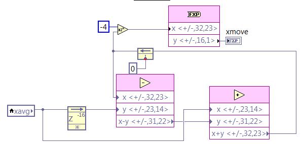
I've got step 1 work correctly using the block "mean, Variance, StdDev FPGA vi" with number of samples on 16. This block runs within a sequence of flat sequence structure after I received each sample 1 kHz on the SPI. My fight is the average feature mobile step 2. I try to use the code in the screenshot below, but am unclear regarding how/where to implement this logic inside is my structure flat separate sequence while loop, structure of the case, etc, in order to ensure that it only works on one of 62.5 Hz samples to this flow of data at once. I tried to put it inside the sequence that executes the block average and further in a case that is driven by the Boolean "valid" the average block output. I obviously don't understand how these different loops run, because it does not work properly. Can someone tell me how to implement the logic of moving average in my vi FPGA existing to produce the desired results as described above? Screenshot below of the logic (step 2) average mobile I am trying to use. In addition, find attached my screws vi FPGA that I need help with is 'CA215_SPI.vi' and the level vi host is 'Host.vi '. Thanks in advance.
Joel
This question is closed. I realized that my approach to implementation was actually working. I just had a stupid mistake on my fixed point output bit size, giving me results errenous.
Tags: NI Software
Similar Questions
-
Acquisition of data in LabVIEW FPGA
Hello
I'm working on LabVIEW FPGA where I need to acquire data from a source and take the average. One way to do that is to continue to add each new signal to the oldest f sum and then averaged.
However, I would like to keep all of the incoming values in a file and save it. But when I tried it doing so, it gives an error message saying "table size cannot be changed. With this constraint, I am unable to write the data to a table.
Please suggest.
Thank you.
You need different acquire data, pass it to the RT, then sign in here. Impossible to use build table the FPGA as FPGA will not allow dynamic allocation of memory like that. You must preallocate the table then use replaces the subset of the table. A better way is to use DMA FIFOs. Have a look at the FPGA examples in LabVIEW for data flow. Then, on the RT, you can simply add in your files logging functions.
-
Simulate the sine wave using LabVIEW FPGA with NOR-myRIO and display in real time
Hello
I'm relatively new to LabVIEW FPGA. I am trying to test (and later apply) controllers high speed on myRIO.
At this point, I'm trying to simulate the sine wave from 1 to 10 kHz using Sinewave generator VI express. I also intend to display the sine wave on the time real (RT) using FIFO. However, I had a bit of trouble to understaing various synchronization parameters.
1. how to encode information about the sampling frequency generating sine wave? (The side FPGA vi requires only the frequency of the signal and possibly phase and does not rate update lines)
2. how to estimate the number of items in a FIFO? (that is, the relationship between the rate of updates to loop (RT), the signal frequency, sampling frequency and the number of items in the FIFO)
It would be great if we could share a very simple program (side host and target) that did something similar.
Thank you
MILIN
Milot,
I think the problem is the type of data in your FIFO. Your FIFO is configured to use a data type of I16. The problem is the number, it displays only ever will be-1, 0 or 1. To resolve this problem, you must send the sine wave as a fixed point data and convert it to a double on the side of the RT. This should significantly improve your resolution.
-
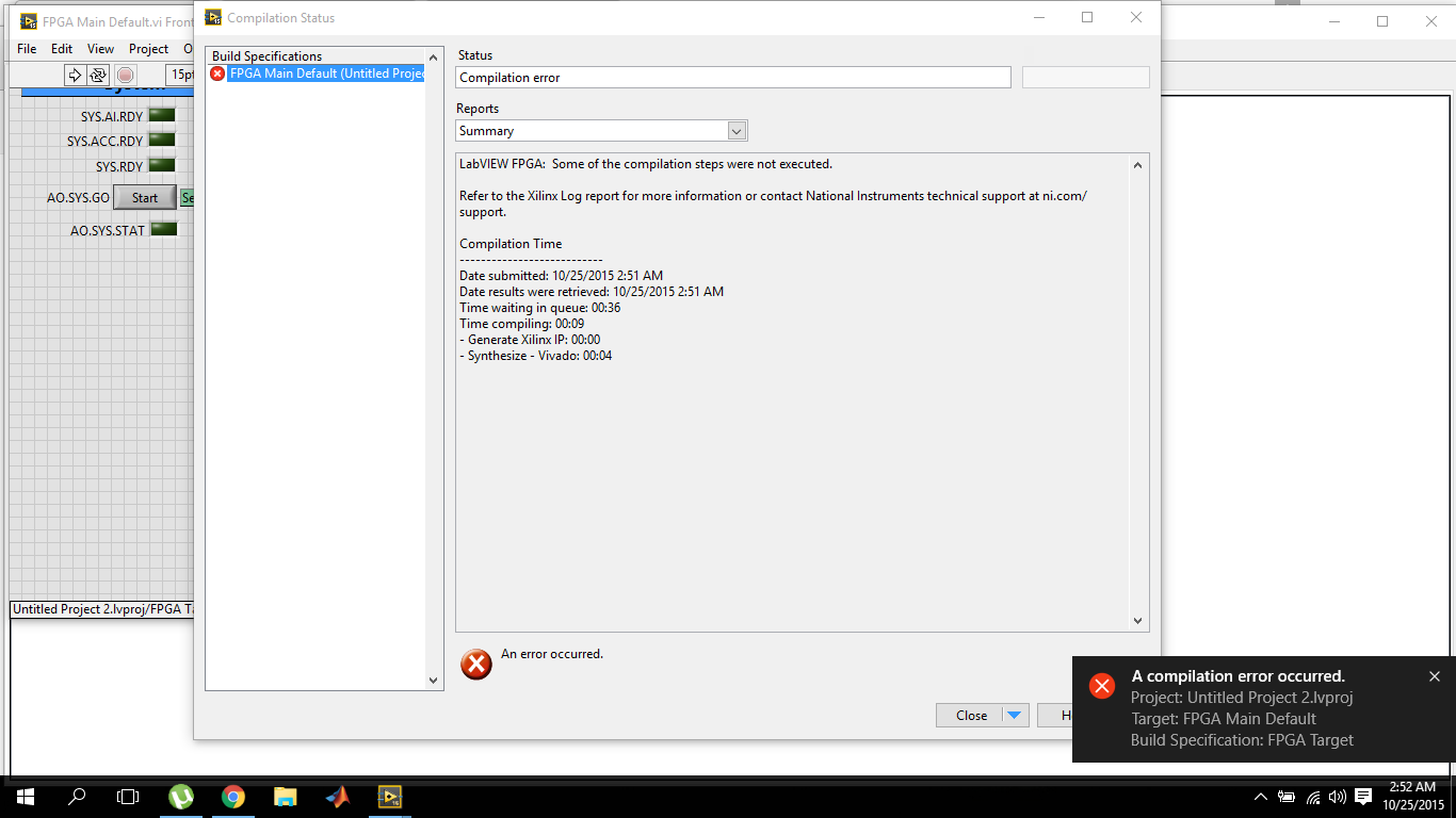
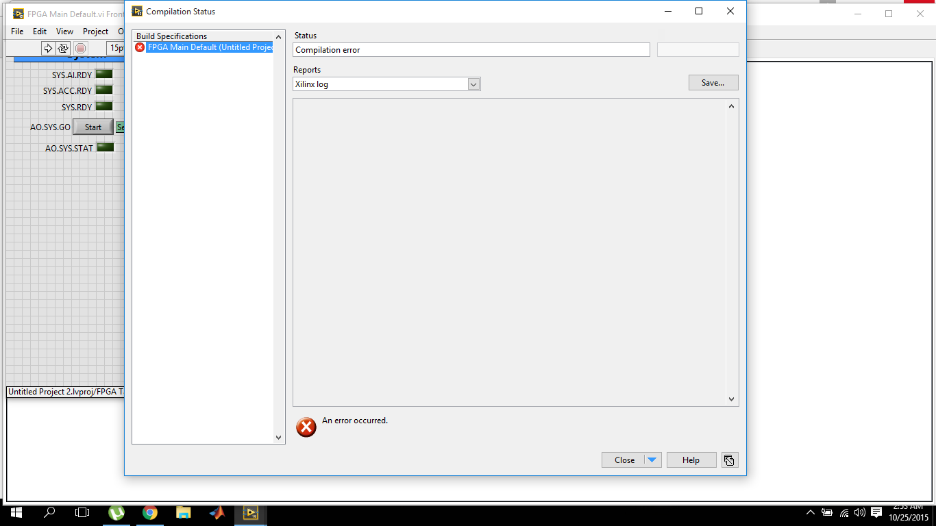
LabVIEW FPGA, 2015 compilation error
I've recently switched to LabVIEW 2015 and I'm working on OR myRIO. So also installed myRIO 2015 bundled software. The problem I have is that the compilation of fpga fails within 10 seconds.
and the target Xilinx journal report is empty
The first time when I tried to compile on 2015 version, it failed and the message box that failed came alongwith the avast antivirus warning for malicious activity. I reported it as wrong and now I tried several times with avast shield disabled control, but the results are the same. While the version of labVIEW 2014 works very well.
Now, I'm sure that there is something wrong with the installation of Vivado because this dll is part of it. The dll must be default in the2014_4\lib\win32.o directory C:\NIFPGA\programs\Vivado if you are using an operating system for 32-bit AND also in C:\NIFPGA\programs\Vivado2014_4\lib\win64.o If you use a 64-bit operating system. If the dll is not here, it is probably that the anti virus (I've never seen what happens to Xilinx but I have for other stuff).
I'm emphasizing the 2014_4 because LabVIEW 2015 uses Vivado 2014_4 while 2014 LabVIEW uses Vivado 2013_4. Since you have also installed LabVIEW 2014, you must have 2013_4 as well and if it works, you will find the dll I just wanted you make sure you check the correct directory for the Vivado 2014_4.
Download and install (reinstall or repair if already installed) 2015 LabVIEW FPGA Module Xilinx tools Vivado 2014.4. You can also use the DVD Setup if you have. It would be a good idea to do the installation with the disabled and even anti-virus try the first compilation the same. Try and let me know if the problem persists.
Kind regards
-
Internal software error of LabVIEW FPGA Module - 61499
I get the error next (in a pop-up window) in the phase of sompilation for the FPGA target with a vhdl IP. This error continues to occur even after restart LabVIEW and the PC. Someone at - it solved is this kind of problem before without having to re - install the software?
Here is the error information:
Error-61499 occurred at niFpgaXml_GetValue_String.vi<><><><>
Possible reasons:
LabVIEW FPGA: An internal software error in the LabVIEW FPGA Module has occurred. Please contact National Instruments technical support on ni.com/support.
Additional information: lack the tag required XML (/ CompileServerList)
As a first step, I can compile the vhdl IP node successfully. However, once when I'm running a VI with the FPGA, the bureau stop working. After that I restarted by force, it cannot perform the build of a vhdl IP node. Even without connecing to the jury of LabView, he pointed out errors before the end of the sompilation.
Interestingly, the screw which also includes nodes IP vhdl that I properly compiled before, I can still run the VI to the Commission and it works correctly.
Thank you
Looks like your ActiveJobsList somehow has been corrupted. I saw occur when computers are hard stop or blue screen during compilation. I don't have that LabVIEW 2014 installed on my machine, so your path will be a little different, and the file extension will be a .txt or .xml instead of .json, but try this:
Move the file "C:\Program Files (x 86) \National Instruments\LabVIEW 2014\vi.lib\rvi\CDR\niFpgaActiveJobList.json" (or your equivalent) out of the above directory (back it upward and delete essentially) and restart LabVIEW. Must regenerate the file and resolve the problem.
-
How to use bidirectional I/O in the CLIP of LabVIEW FPGA?
How to use or define two-way i/o for CLIP with LabVIEW FPGA? I want to use 1-wire communication inside the kernel CLIP, the function will be implemented to read and write as I/O inside the CLAMP.
The XML Generator (CXG) 1.1.0 ELEMENT does not support.
Thank you
Supawat
Work after separate IB pin (bidirectional) at the entrance and exit. Thank you.
-
NEITHER 9512 with Labview FPGA Interface
Is it possible to use the NI 9512 stepper with Labview FPGA interface drive unit or is it only possible to use it with the interface of scanning? When I try to add the module to a FPGA target, I get an error telling me that Labview FPGA does not support this module with the latest version of NOR-RIO, but I have the latest version of OR-installed RIO.
Hi Checkit,
You're right - the 9512 cannot currently be used in FPGA. There is an error in the documentation. The 9514 and 9516 can, however.
-
How to measure the frequency of sampling (s/s) in LabView FPGA?
Hello
I am trying to find a way to measure the sampling frequency (s/s) during which I read from analog input in LabVIEW FPGA. I know that the sampling frequency is specified in the data sheet of the module HAVE, but I want to measure in LabVIEW.
Any suggestions?
A screenshot of the example code would be greatly appreciated
Hey phg,.
If you have some time loopand in this loop, you export a sample by iteration of loop via an I/O node. You can't out two samples on the same I/O node within an iteration, it's always one!
So if your loop takes 1 second to run you have a sampling rate of 1 Hz output. The same goes for sampling of entry. How long your loop takes to run can be calculated as explained above.
Samplerate [s / s] = 1 / [s] while loop
-
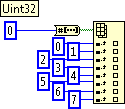
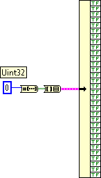
Int split into pieces in LabVIEW FPGA
Is there a clever way to split a Uint32 in 32 bit directly accessible (not a prison guard) in LabVIEW FPGA?
The only way I could come up with is the following, which is a writing of pain for 32 bit and seems a waste resources og to store all these clues.
.
Best regards, mola
I thought about it. I could use clusters by right-clicking on the table to the Cluster block and increase the cluster size in 32.
-
LabVIEW FPGA: Integration node clock wrong
Hello
I'm having some difficulties to understand how the clock is part of the node IP for LabVIEW FPGA and was hoping to get some advice.
What I try to do is to set up a digital logic circuit with a MUX feeding a parallel 8-bit shift register. I created the schema for this Xilinx ISE 12.4, put in place and can't seem to import the HDL code into an intellectual property node. When I run the VI, I am able to choose between the two entries for the MUX, load the output in the shift register, clearly the shift register and activate the CE.
My problem is that when I switch to the entrance of THIS, he should start 1 sec shift (Boolean true, SCR, High, what-have-you) in the registry once each clock period. Unfortunately, it instantly makes all 8 bits 1 s. I suspect it's a question of clock and here are some of the things I've tried:
-Specify the input clock while going through the process of configuring IP nodes.
-Adding an FPGA clock Constant as the timed loop.
-Remove the timed loop and just specifying the clock input (I'm not able to run the VI that I get an error that calls for a timed loop)
-Do not specify the clock to enter the Configuration of the IP node and wiring of the FPGA clock Constant to the clock input (I can't because the entry is generated as a Boolean).
-Remove an earlier version of the EC who had two entries up to a door and at ISE.
-Specify the CE in the process Configuration of the IP nodes.
-Not specify this in the process of setting up nodes IP and wiring it sperately.
-Various reconfigurations of the same thing that I don't remember.
I think I'm doing something wrong with the clock, and that's the problem I have. Previously, when I asked questions to the Board of Directors on the importation of ISE code in LabVIEW FPGA, a clock signal is not necessary and they advised me to just use a timed loop. Now, I need to use it but am unable to find an explanation online, as it is a node of intellectual property.
Any advice would be greatly appreciated, I'm working on a project that will require an understanding how to operate clocks the crux of intellectual property.
Thanks in advance,
Yusif Nurizade
P.S. I have attached my schematic ISE and the LabVIEW project with one of the incarnations of the VI. The site allow me to add as an attachment .vhd file, but if it would help I could just paste the body of the code VDHL so just let me know.
Hello Françoise,.
I spoke to the engineer OR this topic and it seems that it was sufficient to verify that your code works, by putting a wait function of 500 ms on the while loop to check that the registers responsible and clear. I'm glad that it worked very well!
-
Move from LabVIEW FPGA block of ram address to node CLIP?
Hello
I need to pass an index memory RAM of LabVIEW FPGA block to a CLIP node to the node CLIP to have access to the data in the BRAM. The node of the ELEMENT contains an IP address that we developed and the IP address is the use of Xilinx BRAM driver to access data. I guess that we need to move the physical address of the BRAM to the ELEMENT node.
Is this possible? If so, how? If this is not the case, what would be an alternative?
Thank you
Michel
If I understand you correctly, Yes, you should be able to use the memory block of the Xilinx pallet Builder in LabVIEW FPGA and in the loop of the single Cycle, connect the ports of this block signals CLIP exposed by the IP of your colleague. You may need to tweak/adapt some of the signals slightly to the LabVIEW data flow.
-
LabVIEW FPGA CLIP node compilation error
Hello NO,.
I work on an application for my Single-Board RIO (sbRIO-9601) and faced with a compile error when I try to compile my FPGA personality via the ELEMENT node. I have two .vhd files that I declare in my .xml file and all at this point works great. I add the IP-level component to my project and then drag it to the VI I created under my FPGA.
Within the FPGA personality, I essentially have to add some constants on the indicators and entries CLIP to my CLIP out and attempt to save/compile. With this simple configuration, I met a compilation error (ERROR: MapLib:820 - symbol LUT4... see report filling for details on which signals were cut). If I go back to my VI and delete indicators on the output (making the output pin of the CLIP connected to nothing), compiles fine.
I've included screenshots, VHDL and LV project files. What could be causing an indicator of the output of my VI to force compilation errors?
Otherwise that it is attached to the output ELEMENT, a successful compilation...
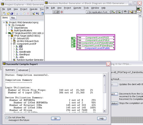
After that the output indicator comes with CLIP, compilation to fail...

NEITHER sbRIO-9601
LabVIEW 8.6.0
LabVIEW FPGA
Windows XP (32-bit, English)
No conflicting background process (not Google desktop, etc.).Usually a "trimming" error gives to think that there are a few missing IP. Often, a CLIP source file is missing or the path specified in the XML file is incorrect.
In your case I believe that there is an error in the XML declaration:
1.0
RandomNumberGenerator
urng_n11213_w36dp_t4_p89.vhd
fifo2.vhd
This indicates LV FPGA to expect a higher level entity called "RandomNumberGenerator" defined in one of two VHDL files. However, I couldn't see this entity in one of two files. If urng_n11213_w36dp_t4_p89 is the top-level entity, edit the XML to instead set the HDLName tag as follows:
urng_n11213_w36dp_t4_p89 Also - in your XML, you set the 'oBits' music VIDEO for output as a U32, however the VHDL port is defined as a vector of bits 89:
oBits: out std_logic_vector (89-1 downto 0)
These definitions must match and the maximum size of the vector CLIP IO is 32, so you have to break your oBits in three exits U32 output. I have added the ports and changed your logic of assignment as follows:
oBits1(31 downto 0)<= srcs(31="" downto="">
oBits2(31 downto 0)<= srcs(63="" downto="">
oBits3(31 downto 0)<= "0000000"="" &="" srcs(88="" downto="">Both of these changes resulted in a successful compilation.
Note: The only compiler errors when you add the flag because otherwise your CUTTING code is optimized design. If the IP is instantiated in a design, but nothing is connected to its output, it consumes all logic? Most of the time the FPGA compiler is smart enough to get it out.
-
LabVIEW FPGA: An internal software error in the LabVIEW FPGA Module has Unknown
Sir/Madam,
Note Labview 2012 SP1 installed about 2 weeks ago.,.
Accident occurred during the compilation of an fpga vi who worked satisfactorally in the past.
When I restarted and went to the message recomplile "LabVIEW FPGA: an internal software error in the LabVIEW FPGA Module" see attached picture of popup.
I reinstalled Labview in its entirety and backed out the changes I made to the vi but still get the same message.
Thanks in advance
Daryl
It turns out that the question was in the VI and not of LabView FPGA module as the message may indicate. I created a vacuum vi, cut and pasted items in this from the vi error and recompiled and it ran very well.
Somehow the vi has been corrupted internally.
Thank you it's fixed.
-
LabVIEW FPGA: Deploy fpga with host program
Hello people,
I develop using a pxi-7831R (FPGA), 7.1 LabVIEW and Labview FPGA 1.1.0. I wrote the fpga code and a host vi and they work well on my development computer. However, I need to create an executable file and take it to my development computer to another computer (which also contains a pxi-7831R), and I don't know how to do it.
Then I just build an executable from my host program and place the 'bit' fpga file in the same folder as the exe and copy it to the target computer, or what I need to somehow add the bit file to my build configuration?
Thanks for any help!
Chris
Hi chassan,.
In LabVIEW 8.x, the exe will offer the bitfile automatically. I imagine it works similarly in LabVIEW 7, but it's probably best that manually regroup you the bitfile in your build options.
-
Zip file and iso LabVIEW FPGA Xilinx tools 12.4 Module is broken
I downloaded the two zip file of LabVIEW FPGA Module Xilinx tools 12.4 and iso image file three times to make sure that both files are broken and can not be installed!
The size of the file is so large about 3g. It would be better to double-check before you download on the Web site.
-Very well,.
The download is complete and the standard Windows Extraction tool worked, WinRAR worked and 7Zip worked (and no, I don't know why, I installed all). I did download a wireless network that does not have direct access to our internal servers, it should therefore be a test valid. If the link I provided above was not that you used (probably isn't, because it is not an ISO option), could you please provide me with a link to the page that you used so that I can test and repair? In the meantime, the link above should work for you.

Maybe you are looking for
-
How can I unhighjack my homepage?
Every time I try to put my default homepage to some stupid "search.conduit.com' and I want to put my own page I chose. I have even uninstalled and reloaded Firefox, but accomplished nothing...
-
Need of reinstallation of Windows MCE 2005 CD
I woud want to reinstall my OS (Windows Media Center 2005) but I don't want to use the recovery cd.How can I buy only the reinstallation of Microsoft CD of Windows MCE 2005? Thank you
-
How to make backups of Photos on an external drive? I have an external hard drive with photos.
-
Does anyone have experience with the addition of an SSD to a dv9999us (dv9700us)?There is a second drive Bay. You wonder if it will take one SATA II or SATA III SSD or possibly an mSATA SSD?
-
BB10 Simulator orientation change?
Is there a clear way to change the portrait and landscape and vice versa on the Simulator? I tried to drag diagonally so many times all I managed to do is to toggle the virtual keyboard. I tried to use the controller, but it doesn't seem to work (tri