Save a waveform in BT 7.1
Hello
I need to know about the economy of a waveform in JPEG or Excel or any other format.
If you want an image, then you can use the Get Image of a graph method and feed the image data to a JPEG file write VI.
If you want numeric data, you can use the write to VI file worksheet. This does not create an Excel file. It creates a text file with delimited columns, but you can open it with Excel. If you absolutely want to Excel so you use ActiveX. Examples are provided with LabVIEW, and more can be found in the thread Excel.
Tags: NI Software
Similar Questions
-
Save the waveform output to a text file when VI runs continuously?
How can I save waveform output to a text file when I start my VI permanently?
I do power profiling and you want to save voltage drop measures continuely.
Oh... I see. I wasn't aware of this.
This is my first time using LabVIEW, so I used one of the example files. There, I just added "Write file to measure" with total input current... and because I used using buttom "continuous run", I added the Activate button to control when I write of the measurement files.
However, ideally, I want to run x seconds or x minutes and then stop without turn off the device that is connected to the battery Simulator of NOR. At present, its reset whenever I hit the 'run' button, which makes me put in place the special test device I want to measure again.
-
Save data indicator "graph of waveform" to CSV
Hello
I want to save the waveform on the indicator of "waveform curve" to CSV to a desired location. I don't know about the option "Export data to excel" but which don't account path desired user. Any suggestions on how to do it?
Just look at your file IO functions. Write to the spreadsheet file, write to file action, etc..
-
tables of fixed size in FPGA compilation error - how to implement a waveform control in an FPGA?
Hello
After being stuck for two days, please let me briefly describe my project and the problem:
I want to use the cRIO FPGA for iterative control of waveforms. I want to capture a full period of the waveform, subtracting a reference waveform period and apply control algorithms on this. Subsequently the new period of correction must be sent again for the output module OR. If it does not work, the captured waveform will look like the one reference after several iterations.
I am planing to create an array of size fixed for the capture and the reference waveform (each around 2,000 items for a given period). I use so 2 paintings of each elements of 2000. I use the function 'replace the subset of table' to update each element captured in the loop sampling and a feedback for each table node to keep in memory (I also tried shift registers, but then the berries do not have a fixed size any more and I can't start the compilation process).
If I try to compile the FPGA vi, I get the following error:
Details:
ERROR ortability:3 - Xilinx this application runs out of memory or met a memory conflict. Use of current memory is 4167696 KB. You can try to increase physical or virtual memory of your system. If you are using a Win32 system, you can increase your application from 2 GB to 3 GB memory using the 3 G switch in your boot.ini file. For more information, please visit Xilinx answer Record #14932. For technical support on this issue, you can open a WebCase with this project attached to http://www.xilinx.com/support.
"Synthesize - XST" process failedBefore I added berries to my code I could compile the FPGA without problems. So, it seems that the tables are too big for the FPGA. :-(
Therefore, I would like to ask if there is perhaps a better method to implement my problem in LabVIEW FPGA? How could avoid the tables to save my waveforms on a period?
Thanks a lot for your help in advance.
Best regards
Andreas
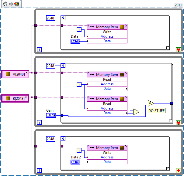
Unfortunately, the LabVIEW FPGA compiler cannot deduct stores shipped from berries (yet). When you create these two large paintings, you are creating essentially several registers very, very large. Just by looking at your picture, I guess that there are at least 4 copies of each of the tables.
You want to use LabVIEW FPGA memories instead. You can create memories outside the loop and then read/write them where you are currently referencing the berries. The only change that you really need to do is to break down your treatment in scalar operations. I have attached a simplified version of your plan, I hope it helps. Let us know if you have any other questions.
-
Plotting the amplitude of a spectral peak over time
Hello
I am creating a VI where the acquired continuously DAQ, plots and save a waveform in millisecond delay (which is already done in this case), then takes this waveform, finds a specific pic (probably the first) and trace the amplitude of this pic over time (+ 30 minutes, one point each scan which is obtained). Essentially, I have a detector quickly attached to a chromatograph, and I want to select a single ion and monitor the amplitude of this ion. I can draw the waveforms along with it in post processing, but I want to do is to have the 'slow' constantly plot to update and display when it moves through time. Joined the VI will go in, using IMS software V1.3.vi, the paragraph is the "GC" Mode it seems I should use the "peak detect.vi.", but I'm not familiar with this operation, and so I don't know how to show a constantly updated graphic or remove the amplitudes and draw. Thank you for your help,
<><>
Eric-WSU wrote:
I get an amplitude on plot of time, but it does not appear until after all the iterations are stopped
I have not watched your VI (because I'm in a previous version of LabVIEW), but it's probably because your graphic is outside the loop.
Here's how you can get a graph of the peaks (all vertices, by iteration):

Or if you want to only a certain PEAK (and how this pic changes with the number of iterations):

-
That does Create DAQmx Virtual Channel (TEDS AI accelerometer) actually?
Hi all
I have a logging application of fundamental vibrations for which I use TEDS accelerometers active. I set up a task using the virtual channel create (TEDS AI accelerometer) to add the right channels, but none of the data in the table of TEDS seems to be get attracted to my channels.
This VI pulls information of the TEDS scaled such that the values I have read are resized to the appropriate unit? Is it possible to force it to drag all the TEDS data by so that when I save a waveform to a tdms file they end up like channel properties?
I've included a screenshot of VI, which creates the task for reference. Thank you!
-
recording of signals graphic permanently
Hello everyone. I have been working on recording the signals constantly. What I mean is, if I run the vi for 5 minutes, it will save the waveform from the beginning until I have stop the program (5 minutes). I managed to record the signals in jpeg format, but the problem is every time I save the image, it will overwrite the previous one. Y does it can someone help me?
-
I need to capture traces of scope of ~ 20 per second (2500 points per track).
I have a TDS744A which is dong at best 1 route per second with LabView and GPIB. I can go through a few cups of coffee before my data...
All the recommednations on scopes that are capable?
Tektronix scopes are up to? How are LeCroy scopes in this matter?
Any experience or summaries are appreciated.
Best regards
Richard Burton
ON Semiconductor
Hi Richard,
Alan and LeCroy Support here...
The answer is Yes - the series Waverunner Xi can transfer about 24 forms of wave/sec when the scope is set to an acquisition of 2500point in mode 'Real time' (which is the standard operating mode)
You can transfer a much higher using 'Séquence Mode'. In this mode, the scope of application records several triggers for extremely low memory with deadtime. I find that I can transfer, for example, about 14 sequence mode acquisition per second, with each acquisition, including 10 triggers of 2500 points each, which amounts to 140 triggers per second transferred.
The best way to use will depend on your application. For example, if you plan an average of waveforms or perform another analysis, you can do it on the field of application and save a lot of time. Or, if you want to save the waveforms on the scope, you can save about 30 signals/s in real-time mode.
Please call me at 800-553-2769 for more information!
Best regards
Alan
-
How to add a record button on the front panel to save waveform data
Hi, I'm new kind of LabVIEW and I worked on a code for an agilent oscilloscope communicate via GPIB and so far it works well on the collection of these two analog channels one by one, "Not UNLIMITED" but it does the trick (vpp, Vrms, frequency, etc.). I've added the feature to add data to a .csv file waveform (problem: opens a dialog box until the user gathers all the data.) Solution: I want the user to save the. File CSV whenever he wants to use later on the front panel). I've added another feature to get a snapshot of the curve waveform (problem: opens a dialog box.) Solution: I want the user to save the JPEG file, whenever he wants to take a snapshot ("take snapshot" button on the front panel)). I work with the agilent hp54645d driver. I have attached my code, if someone can tell me please how do I do this (maybe cabling and structures are solutions do not know). Thank you in advance.
I would recommend adding a case structure just around the two record VI and a button to check the condition of the structure of each case. If you want a button to control both save functions you can put the two record functions in the same structure of business controlled by a single button. You are right in saying that the loop will cause your code runs until the stop button is pressed or until the stop condition is met. If you are wanting the while loop to stop once the recorded information you can use the button that you use to control structures case to also stop the while loop. I hope this information helps.
-
Save the digitizer and DIO waveforms in a single spreadsheet file
I use mixedsignalscopeusingtclk.vi attached data acquisition and want to acquire 4 channels of data. My system PXI-1042 PXI-5122 and PXI-6552, and I use 2-channel digitizer and 2 digital i/o channels. I'm using Labview 2010 SP1. The VI generated table 1 d of the cluster for an analog waveform and table 1 d of digital waveforms. How to save the two waveforms on a worksheet?
Hello
You can use a write file express VI measure. Note that this is the easiest but not the most effective way to write to a file.
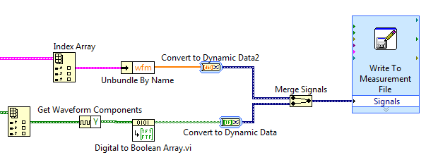
Since you have the extraction screws inside loops, your output is a table 1 d of waveforms. You will need to obtain the wave form and convert it to a type that can read the express VI. If ungroup you the waveform and retrieve only the data and connect directly to the express VI, LabVIEW will automatically place a block of "Convert to Dynamic Data" online to make it compatible. This also applies when you connect the Boolean matrix at the entrance of signals express VI. And if you connect more than one signal to this entry, LabVIEW will automatically place a block of "merge signals."
If you reproduce the code below, you should be able to write both channels in the same measurement file. If you have more than one channel of each type, you can enter multiple items using the same table Index block and take them through the same process shown below.
I hope this helps.
-
With an average of a spectral waveform and view / save
Hello world!
I am currently on a University project that consists on the use of Labview to obtain data and spectra of atmospheric plasmas using a spectrometer Ocean Optics HR4000.
After not not using Labview for almost a year, I managed to get most of my knowledge back and I managed to display the spectral waveform, that I expect to get. However, as this is a fairly simple design I get a lot of noise and I would on average it for a graphic display more smooth.
I looked into a lot of messages from the forum, but I couldn't really find what I was looking for.
I also had a problem when you try to save the data and Spectra: I can't find anything in the directory of my VI.
In the attachment you will find the current VI I'm trying.
Thanks in advance for your answers!
Jeremy
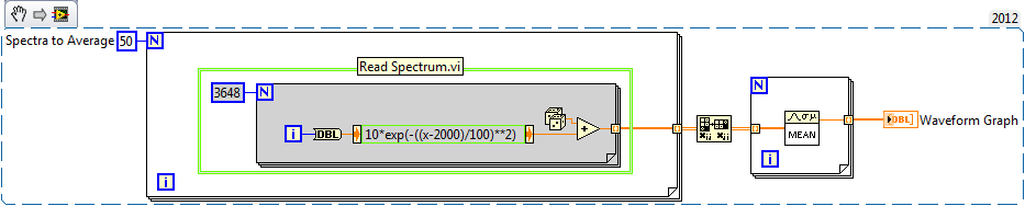
I wrote an example for you below. This is an excerpt from VI, so you can drag the .png in your diagram and it becomes code. Pretend that everything in the green box is your Subvi spectrum acquisition.
-Place the Subvi in a loop to run as many times as you like on average there
-Out of the loop For is a table 2D with individual spectra on the lines
-Transpose output, so individual spectra on the columns
-Enter the table another loop to take the average rank by rank (with an average of different Spectra togeter).
-Output is 1 d spectra average table
-
How can I save a table 1 d of waveforms in excel
How can I save a table 1 d of waveforms in excel. The picture is from a vi that reads and graphic a wav. file
Hi Navident,
Before you create the excel worksheet do not forget, you cannot configure Excel to exceed the limit of 65 536 rows and 256 columns in Microsoft Office Excel 2003. I hope that the HRT help for you
.
Siva
-
How can you save waveform data w / an iteration variable?
No one responds to my messages, three Ive packed in the last hour, no one knows how to do this? I don't think that's the problem.
Please help me, I need to save waveform data, however several times a second the user said, I have one already done 'iteration timer' but it does nothing.
Please, if you can help me, I use LV8.5.1.
Thank you
(I am a very new user.)
-
Error data truncated when loading saves waveforms
Once I recorded a waveform using the 'write waveforms in a file' VI (for example I save it as wave.lvm), I tried to load it using the VI "waveform reading a file. I always get an error about not flattened or truncated data (error 116). Any suggestions?
Hello boomchild06,
After having had a detailed look at the various databases that we use, I discovered that it is a known issue with LabVIEW 8.0.
Workaround was proposed as follows:
1. place the waveform of File.vi reading on the block diagram and double-click it to open it.
2. go to the diagram and click twice on the Open create replace WDT DLog File.vi and discovers the block diagram.
3. navigate into the structures of the case until you see the service to deny access. I suggest you save this VI as something different from this moment on, so that you do not change the screw in the vi.lib folder.
4. Once you have the re-recorded with a different name, and I would say in a different location, follow the exit of the bunch of the error in the structure of the case that it is connected to. I navigate to the case of fake and then made a right click on the border to eliminate the species.
5. Once this is done, you can remove the whole box structure. I could recommend this way to avoid a lot of painful rewiring.
6. Once you have removed, you can remove any broken wires, unbundle function and the function is equal to zero. You can either choose to disable the feature to deny access, to avoid error pop ups.Alternatively, the fix has been implemented in LabVIEW 8.0.1 update which is a free patch that can be installed. If you want to go ahead and install this, it can be downloaded from:
http://digital.NI.com/softlib.nsf/webPreview/4C1209D42320BCFD8625711C005FB25B?OpenDocument
I hope this helps.
-
Save the Studio measure waveform graph as a file for reading later
Hello
I would like to know if there is an easier way to record data are rendered on a waveform graph (configured as a graphic of the band) to capture incoming data in the code and send copies of it to a file. It would be nice if there was a method to do this, with all relevant metadata stored in the file (color, etc.). Better yet, the file could then be opened in a labview application (for example, a TDMS file) for later review.
Thank you.
PS. I use VS2010 and MS 2010.
So, it looks like you already have all the data points. For metadata that you mentioned, line color, plot colors, point colors, line styles, etc. are all accessible from the properties so if you wish, you can retrieve all that data.
I think that upon return from t0 is the same compensation history, you can use the ClearData() method.
Maybe you are looking for
-
I'm late to the discussion of problems Outlook-iCloud. I have Windows 7, Outlook 2013. iCloud slipped all my elements of calendar and contacts and completely wiped out my mailing lists. All I want is to get rid completely of iCloud for Windows! I und
-
additional icloud and full phone storage
Hello I have an iPhone 6, which currently has no free space. For example if I go to take a picture, I'm greeted by pop up saying that I have more storage and need to manage to clear space. I have a 50 GB of space icloud, but appears not to me will be
-
Toshiba Satellite click 2 Mini - impossible to reinstall Windows OS
My toshiba mini right2 stopped working so I reset and tried to burn it all up even 10 and 8 to several usb drives windows to reinstall windows but when I boot in windows settings it does not I can't touch the screen to change the options or go forwar
-
Hey,.A week ago, my CD-ROM started acting weird. It doesn't read any cd what so ever. I want to replace it, but my question is... I can do it myself, and if not it'll be expensive...? My Toshiba Satellite is a series of 400-1800
-
Since the resettlement 4.2.1 JDE to my rebuilt the machine any instance of a class can I write does not seem AutoComplete for the names of fields and methods. Can anyone think why?