sbRIO-9631 digital inputs/outputs using e/s node FPGAS and FPGA of i/o method node
Hello, I'm trying to configure my SBRio-9631 for the first time. I try to use the on boards to inputs and digital outputs. The following code will work? This is a simple "read the entries, 'or' some inputs and pass ' exits." I have to add "E/s method nodes FPGA" between my 'FPGA of i/o nodes"to get"modes of State of sorting for the input and output lines? Also, I can't simulate/test it works, by adding 5 VDC at the entrances, and not have any source of voltage output. Thank you for your time.
Hey, Spex,.
I really, really appreciate your help. Your follow up information was exceptional.
Thanks again for your help and your time.
gjmm
Tags: NI Hardware
Similar Questions
-
OR 9403: Digital Input/Output slows timed loop?
Hi all
I use a loop timed sample of 7 current channels (NI 9023), 3-channel (NI 9025) voltage at 1000 Hz in scan mode and it works fine. However, when I add for 8 output channels of the input/output module digital module NI 9403 for timed loop, CAPAS sampling cannot exceed 1000 Hz. According with time stamp data I wroten in file, it seems that I have in all ten milliseconds, I missed a miliseconds.
I would like to ask is there a reason for this? The digital I/o module affect the timed loop?
Thank you much in advance.
I'm not familiar with the FPGA code, so I can't comment there. However, I noticed that you call writing to text file twice in the timed loop. Can you only collect data and then write the files after the time loop? This would save a lot of time. For each entry, the program needs to access the hard disk, find the end of the file, add him and return to write on the hard drive. A lot of your time, especially since the files are getting bigger.
-
is there a vi for inputs/outputs using AWG (PXI-5421) and DIG (PXI-5122)?
Hi, I'm looking for a vi that applies to an input through the AWG (PXI-5421) signal and measures the output through the SEARCH (PXI-5122). In particular, I'm trying to apply an entry by a multiplexer, then close this channel of the multiplexer through which the entry came and then measure the output using the SEARCH signal.
Any help will be greatly appreciated.
Thank you.
Hello Deepjunior,
I understand that you wanted to find an application that will be output on an AWG device and acquire a table digitizer at the same time. While there are many methods to achieve this, the easiest starting point would be to just take a simple example of niFgen and a simple example of niScope and run them together or combine them. According to exactly what your application requires, you may need to implement additional features, but it is a good starting point.
In particular, you can find an example of this from the example of area developer program: OR-TCLK synchronize AWG and digitizer high speed. Basically, this example combines niFgen and niScope examples and using the API OR-TCLK to synchronize devices. I recommend watching the program and trying to start from there. Hope this helps,
-
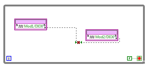
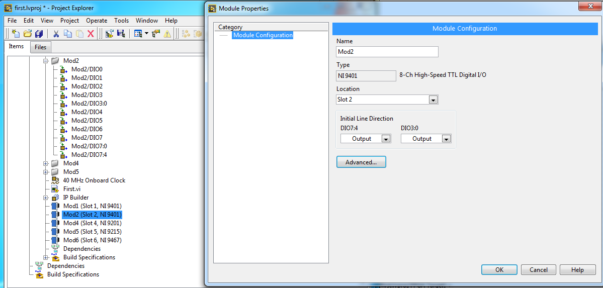
Configuration of the inputs/outputs of NI9401 in labview FPGA
Hello
I am very new to Labview FPGA. In fact, I'm implementing the very first example introduced by OR for learning Labview FPGA. I need to connect an entry of a NI9401 on one exit from the other.
However, when I drag and drop the input/output units, the two act as inputs:
I also changed the propties one of the NI9401 to act as output. But the problem persists.
It is the example that I am building.
I'd appreciate any suggestions.
https://www.YouTube.com/watch?v=mv112V-P030&index=1&list=PLbCk9hRe-ziECXQjE--fN29C_kcx7CHnA
Right-click on the output node, and then select "change to write."
-
Problems with the digital input/output
Hello
I have a little problem with my card PCI-6143. I would use two connectors digital one as a starter and one as an output. Now, I have the problem that I do not know how I address them. The input works as I want but not the output.
As an example. I call my channel output on this name: Dev1/port0 / line0:0.
With this call, the application works very well. If I change the output channel to Dev1/port0 / line4:0 I get an error that the values can be read and 0 and 1 are valid values.
I hope that the call is right, I wrote that out of my head.My questions are. Is it correct to call a single digital channel with this name?
I'm not sure because I do not understand what these means 'line' and if I allocate really single channel or more.
The second question is, can someone give me an example of how I assign two digital channels (how to address them)?
I know it's maybe an easy question, but I can't seem to get it corrected.Hope someone can help me.
Best regards
The syntax that you use is intended to select several channels: the numbers are the initial and final channel in a subsequent channel list. Thus, written Dev1\port0\line0:4 means 5 lines are included in the read/write (FWIW written 4:0 has the same effect). It is redundant but good writing line0:0, which means a single line, but you can write to Dev1\port0\line0 which is simpler.
This is a help page on this topic.
-
sbRIO-9642 digital input maximum input frequency
Hello
I would like to know what is the maximum frequency of entry for the 24V sbrio 9642 DI.
Thanks for your help
Gil Maor
If you use the NI CompactRIO (http://zone.ni.com/devzone/cda/tut/p/id/7338) scan Mode, then your maximum update frequency is 1 kHz. Scan mode still uses the FPGA, but it does not need to write the FPGA code. To learn more about scanning interface, read the link above as well as this one:
http://zone.NI.com/DevZone/CDA/tut/p/ID/7693#toc1
Now, if you use a meter with scan mode, he can read entries counter at a high rate - it will just update the code in real time at a slower rate (up to 1 kHz).
-
Portege 3490CT - inputs/outputs
I have a problem caused by drivers being removed from the machine according to me. I can't input/output using the external remote diskette, CD Rom, or USB port.
How can I install new drivers without internet access?
Hi Thom,
If you have isolated your notebook all your i/o devices, your only way to restore access will restore your full operating system of your recovery disks.
However, before I do something drastic, that you can try to start in safe mode to see if this will allow you to access your external devices, or you can try to restore your system to a previous restore point (assuming you are using XP) before your drivers has been removed.
HTH
-
Digital input to Toshiba 46TL-> no analog audio output to amplifier
Hi all
When I connect a video source (e.g. computer laptop via DLNA) to my 46TL, output TV audio analog (red/white taken connected to an amplifier) does not work.
It does, however, watching television.
Is it possible to configure the TV to read the audio data from digital input (HDMI/DLNA) to the analog output?
Thank you for the help
Not quite what series of TLxxx you have, but for example the TL938 supports a digital (optical) audio output port that provides a digital audio signal.
Why n t connect the amplifier to the TV using this Jack?Connectors for component video / audio to the rear of the TV are the ports of ENTRY and not the OUTPUT ports. So, you can send an audio signal to the TV and not the amplifier output.
-
6259 switch digital input to output
Hi all
I use the NI PXI-6259. One of the digital inputs I want to switch to digital output, send a serial code and switch again one digital input.
Does anyone have experience with this kind of configuration change during execution of the VI program.
Thank you
Basically delete the task that he had as an input, create another task DAQmx with channel configured as output, this task, erase it, create the task with channel configured as an input.
If you need a tight with switching schedule, I wouldn't recommend this Board. You may need to set up a Council of RIO with LabVIEW FPGA.
-
Definition by digital input or output channels program
Which classes/methods in Measurement Studio NIDAQ-mx support let me set programmatically a digital channel for entry or exit? The only methods I met provide lists of channels of i/o configured previously.
Thank you
If you are using a device with digital two-way lines, then you have not specifically set a channel as ot of input-output. Use string functions DAQmxCreateDIChan or DAQmxCreateDOChan with the lines that you want to use. The line will be automatically configured as input or output.
If the device supports the digital two-way, you cannot define an input as string vice versa and the output channel.
-
9421 sinking digital input module toggles output
I have a digital input module 9421. I'm only using a single port (0). The line is 'high' all the time. I can see it on the lights and the tool MAX. I can turn on/off the line and see the LED and MAX change, so I know I have the cable correctly thing. But in normal operation, it is always powered.
It is, when I run LabVIEW mode trace with a probe on the output ExpressVI DAQ, I see that all the other times my code, the output of flicks from true to FALSE and vice versa... and so on. The acquisition of data ExpressVI is inside a while loop.
Any thoughts?
DH
I have chosen the cDAQ "simulated".

DH
-
Digital input and output problem
Hello:
I do a test for digital i/o:
for a table of the digital signal to an output of data acquisition in the digital input to detect the output signal.
(bascially, it's like a loop that goes outside the material)It's pretty simple, as shown in the attached fichier_1.
It works well.
The manual light switch controls, which means that inputs and outputs are ok.Then I went on the low level DAQ for better speed, as in attached fichier_2.
But it does not work. Especially when I pressed stop to abort the loop, an error has occurred:To speed up, I went to the low-level data acquisition as the fichier_2 attached.
But it does not work. Espeically when I press the "stop"button to exit the loop, the error occurs.Possible reasons:
Requested value is not supported for this property value.
The value of the property may be invalid because it is in conflict with another property.Property: SampTimingType
Asked the value large clock
You can select: on requestI don't understand why the sampling time has a conflict here.
(It is probably just something very simple in data acquisition, but I checked a few examples and did not find a clue).
Hope someone can give me a suggestion.Ultimately, my goal is to make the attached file_3.
In this one, I generate a digital output, and then lead to the entrance.
Then I can take it as a signal to trigger my other task.Note:
I use a similar conti signal to control one of my camera.
I need to sync it with my another task.
So I think to generate a digital output (which share the same clock as the signal similar to the data acquisition device), then put it in one of the digital input.
By detecting this digital input, I can trigger my task and synchronize with this signal similar.
My camera's USB-6211.
I am aware of the latency of USB, but once the value is a constant value, then the synchronization is always good for me.
Actually, I was using an analogue at the entrance of the to do it before, it may work, but the synchronization error is too big for me.
I need to do some calculations/judgment for this analog value, which makes the time difference varies.
So I'm trying digital entry now and I hope that the digital input can trigger my task with a stable latency.Thank you very much
Have you looked at the specs? It clearly states that the digital I/o is a programmed software. You have not any hardware clock at all. The best rate that you could possibly achieve is around 1 kHz and which would have a considerable jitter the nature of non-determimistic of windows.
-
9421 sinking digital input toggles output
I have a digital input module 9421. I'm only using a single port (0). The line is 'high' all the time. I can see it on the lights and the tool MAX. I can turn on/off the line and see the LED and MAX change, so I know I have the cable correctly thing. But in normal operation, it is always powered.
It is, when I run LabVIEW mode trace with a probe on the output ExpressVI DAQ, I see that all the other times my code, the output of flicks from true to FALSE and vice versa... and so on. The acquisition of data ExpressVI is inside a while loop.
Any thoughts?
DH
I had selected "simulated" cDAQ

DH
-
Focusrite scarlett 2i4 unable to use as audio input/output device
I just bought a Scarlett 2i4 hoping that time would have been solved compatibility problems. However, I'm unable to use it as an input/output device. Site Web Focus rite has a class compatible mode download that is supposed to solve this problem. And I installed it three times without success. Has anyone else had this problem and found a workaround. Thank you! I have a macbook pro mid 2012, el capitan 10.11.3.
Don't know if this will help.
I have a 2i2. When I got it, a few BONES in there, I couldn't make it work. I went back and forth with tech support Scarlett. They really tried, even sent several beta drivers. Nothing works.
Then I uninstalled all the software of Scarlett and restarted - and it works.
-
Can I use Premiere Elements for (3D) HD video editing on the SURFACE PRO 3 (i7 8 GB) in m2ts (input/output)?
Elements does not support 3D, and I doubt that it is running correctly on a Surface.
Maybe you are looking for
-
Three beeps when trying to install snow leopard
Hey guys, this imac has el capitan, I am trying to reinstall snow leopard but I get 3 beeps. This research, I came across info suggesting either bad ram or I'm going to need at least a 10.6.7 to a flash drive as suggested in this thread here: three b
-
How to connect TV again WT8-B-102
Hello I have toshiba still wt8 b 102. I don't have a micro hdmi, micro usb only. How can I connect my tablet to tv (no wifi)? Post edited by: kropek
-
"Socket.h" is available for LabWindows/CVI
I'm trying to use a third party API with LabWindows/CVI. I get a compilation error that says 'socketaddr_in' is undefined. On Unix/Linux systems, this parameter is defined in the include file "socket.h". I searched my system (Windows) for "socket.h".
-
I couldn't stand not to listen to my Sansa clip in the car, and the thing of the transmitter just cut it for me, so... I got a new stereo system with an mp3 Jack installed today. I'm so happy. Now I can listen to Rhapsody on my Sansa in one place any
-
I can't understand why my laptop does not start automatically to the top of the card wireless from the start. Must always click on the WPC54G and then pass by the site survey and then enter the WEP key whenever I want to open a session on the interne