self-calibration of NI PCI-6251 (series M) using the kit DDK
Tags: NI Products
Similar Questions
-
write the multiple value series buffer using the structure of the case
In this VI, I am generating waves by using the sliding bar. After that I compare it to a value as 0.6. If the value of wave is higher than 0.6 then led flashes and structure case written 1 value serial buffer. If it is less than 0.6 became led off and structure written case value 0 in the stamp series. now, I want to add another condition if the chart value is between 0.2 to-0.2 written structure case 2 series buffer value. can you tell me how can I do this?
-
Guys keep with me, I'm another PLCs and VB/C programmer, there are still the old paradigms of locking my head.

See attached vi. After that I disconnected the entry in the series, the wizard exits still instrument 0,0 to its terminal at regular intervals about 1 hz. Now how does the wizard output always inst 0.0 without a trigger entry series? There must be a timer somewhere... but I searched everywhere there is no timer, including by opening the front panel of the wizard of the instrument. I watch the whole bulk of the loop and block VISA etc, there is no synchronization setting.

So my question is, if there is no entry of series by using the instrument, which is the parameter object that triggers the instrument Wizard still out 0,0 at regular intervals? Where the object/setting?

Thanks in advance
Great big thank you! I can sleep tonight! Muahahahahahha!

-
OR PCI-6251 correct integer scaling
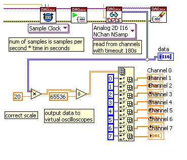
I use the NI PCI-6251 and DAQmx in Labview to acquire the tension given with the set - 10V,-10V range. I want to acquire raw 16 bit non adjusted integer of the map data and save to disk, but I want to display data to the scale on the scopes of my slave to data. I'll also have to evolve then saved data to be analyzed in MATLAB.
I assumed that the scale factor would be 20 /(2^16), but when I display data scale in this way that I seem to be getting slightly different readings that I do when I'm DAQmx acquire and display data directly bracts.
My approach to data acquisition is presented here:
What is the correct method of scaling of this card?
Thank you
-Jack Wimbish
Hi Jack,
Series-M devices like your PCI-6251 calibrated in the software, which means that you cannot use the method of multiplication by voltage range and dividing by 2 ^ 16. To see how to get the correct scaling coefficients, please see this knowledge base:
http://digital.NI.com/public.nsf/allkb/0FAD8D1DC10142FB482570DE00334AFB
Hope this helps,
Dan -
Analog triggering on PCIe-6251 using BNC-2120 on Mac Pro?
Hello all-
There, does anyone know how an analog trigger using a PCIe-6251 card connected to a box of BNC-2120 interface? I am running LabVIEW 8.6 on a Mac Pro OS 10.5.6 and my VI of analog data acquisition seems to work but hangs up waiting for a trigger. The trigger analog signal must be applied to the terminal APFI0 and the BNC-2120 contains no connector with this name. On the M-series cards, APFI0 corresponds to pin 20 on the map itself, but I was not to locate any information that shows how the pins of the connector BNC-2120 connect internally to different spring on its façade and BNC connectors. Sales people NOR recommended the BNC-2120 as the correct one to use with the PCIe-6251, interface box so I think that probably one of the many connectors on the front panel of the box is wired to pin 20. Am I wrong? I spent hours to connect signals to the box in the hope of getting a trigger, and nothing has worked yet. To make matters worse, reviewing the VI to trigger a data acquisition using a TTL signal connected to all of the PFI 0... 9 connectors on the BNC-2120 just causes of VI to give undefined error message ' specific 89136 route cannot be met because the hardware does not support it.» The specifications for the PCIe-6251 indicate that a digital trigger should be possible through the PFI connectors, so it's a puzzle. I have an interface BNC-2110 box in the case which turns out be a solution, nothing about it is named APFI0 either. Any suggestion would be of interest. Thank you.
-Ken1
Hi Ken,
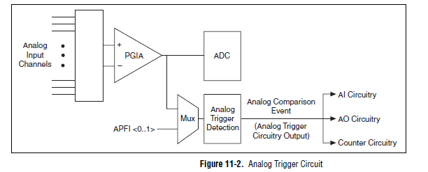
Unfortunately, the BNC-2120 doesn't have a connection available on the APFI your M series line. The BNC-2110 has this connection available.
A possible workaround is that you can trigger off channels of analog inputs as well. Here is a screenshot of the M Series User Manual that shows the analog switch-off circuits:
There are a few caveats to trigger off AI channels (mentioned in Chapter 11 of the manual)
If you use a trigger to start, the analog channel that will be triggered off the coast of must be the first string in your scan list.
If you use an analog input as a reference or a relaxing break, it must be the only channel in the scan list.
I hope this helps!
Best regards
John
-
Synchronization between PCI - 6251 / PCI - 7811R
Hello
I need to synchronize two card PCI, PCI - 6251 / PCI - 7811R. This is my first time with a huge app, and I don't know where I should start.
PCI - 6251 I connected SCXI - 1001, (in chassis: SCXI-1161,-1326,-1327,-1125,-1324) and I'll use it for measurements. Through the PCI - 7811R I want to communicate using the JTAG Protocol, SPI and meaby measure PWM signals. I'm not sure that anything is possible.
Please help me or give me some tips where I can find some examples.
Kind regards
__behemot_
Hi __behemot_,
First synchronization between these two modules can be done thanks to the RTSI, the easiest way bus. The two modules must RTSI connector, so no problem should be there. You can find useful information on the RTSI bus on the following link:
http://zone.NI.com/DevZone/CDA/tut/p/ID/4322
Also search NI example Finder on RTSI, you will find beautiful examples.
Concerning the programming of FPGA section, the following links are of course useful when it comes to digital Communication Interfaces and PWM on FPGA:
http://zone.NI.com/DevZone/CDA/tut/p/ID/5385
http://zone.NI.com/DevZone/CDA/EPD/p/ID/4725
Please also check the NOR example Finder (easier to find in LabVIEW is the Help menu): in search for a selected tab Toolkits and Modules--> FPGA--> series a. here you can find a lot of examples that may be useful to start.
Let us know if you need anything else!
Best regards
David Varga
Technical sales engineer
NIH
-
PCI-6251 - Acquisition on hard drive
Hello
I bought a PCI to acquisition model Multifunction PCI-6251.
How much time Prime Minister of United Nations of in the know I'd like to connect a hard drive directly on this card, and what should be the characteristics of this hard drive in terms of size, speed of rotation and memory cache.
From there, what are the software configurations allowing the acquisition of half a score of analog channels directly on the hard drive? Can we start the recording of the tracks on hard drive from Labview? And how the get?
Finally I would like to know what kind of performance I could you reach in terms of number of "recordable samples and frequency acquisition
Thank you in advance.
Hi all
xdaf is correct that you will need a host PC to communicate with the 6251. The 6251 can acquire analog inputs to 1 MHz multiplexes (for 10 channels that would be 100 kHz per channel), so you will probably not all the problems at these rates simply by using the DAQ Assistant as mentioned xdaf. That said, I wanted to take some time to more carefully address the following question:
Q: "therefore, what are the software configuration used to acquire a dozen analog channels directly on the hard drive?"
A: DAQmx 9.0 introduced a very cool feature called DAQmx Logging that will allow you to easily optimize your streaming to disk. You can read more about it in the link provided, but essentially this function allows you to write directly on your hard drive since the DMA buffer without going through the application memory. Comparing the two methods:
Old method: FIFO edge > buffer DMA > LabVIEW memory > buffer DMA > hard drive
New method: FIFO edge > buffer DMA > hard drive
The new method will use minimum CPU since all transfers are implemented by DMA. The result is a binary file of PDM (2 bytes per sample on a 16-bit card) which can be read with the viewer PDM or imported in LabVIEW for analysis. The file header stores the calibration and scaling information. If you need to integrate this file with other software, the following link contains more information: TDMS integrating third-party programs
You also have the option, if you want to import the data into LabVIEW to look at one/one immediate treatment.
I would probably also add that the benchmark of 1.2 GB, mentioned in the DAQmx logging Article would require a faster bus and configuration of the hard drive. We used two 2 x 8164 matrices Raid in conjunction with a full chassis SMU cards simultaneously. The 80 MB/s this mentioned xdaf is on par with some hard disks more quickly and is close to the practical limit of the speed of the PCI bus. This is information probably just extra, since the data from your card PCI-6251 will be far from this limit.
Even if rates continuously to acquire from a single card PCI-6251 should not be too demanding, I suggest you look into the new DAQmx 9.0 streamline registration of your data, optimize code and functionality for fast disk with minimal use of CPU. I hope this has been helpful!
Best regards
John
PS once DAQmx 9.0 is installed, several examples can be found of LabVIEW under help > find examples... > DAQmx > Analog measures > power > TDMS Streaming... VI
-
analog input PCI-6251, implemented
Hi all
Can I set the analog inputs of the PCI-6251 in configuration of mix (some in differential mode) and others in single ended mode. Because in my set up the differential option is grayed out.
Thank you
dphan128
Yes, you should be able to do. You have 16 analog inputs. Differential, you will use two of them per channel. See the manual of series DAQ M. you can program channels on a M Series device to acquire with different
reference to the ground. To allow m
ultimode sweep in LabVIEW, use OR-DAQmx create
Virtual channel.VI of the API OR-DAQmx. You must use a new VI for
each channel or group of channels configured in another mode of entry.
Don't forget that for a premium that you would for example wire HAVE 0 to the + side and AI 8 - side. So now you can not use the AI 8 for simple nerve. HAVE 1 corresponds to the AI 9 etc. until 7 AM, GOT 16.
I hope this helps.
-
Entered analog PCI 6251 not extent of tension of a mass flow controller
Hey,.
I have a data PCI 6251 M acquisition with a break in Council SCXI 1302.
I'm trying to measure a 0 - 5v analogue output voltage from a mass flow controller (check picture of PIN)
When I measured with a digital multimeter the voltage of the flow signal (PIN2) and common signal (PIN12) I get a stable right tension between 0 and 5v depending on the flow set up. I can control the amount of the charge by providing a data output set point PIN8 and common PIN12 of the 0 - 5V analog signal.
Now when I connect the signal flow PIN2 and on my DAQ signal common PIN12 AI and AIGND, I don't get readings on my labview VI of the AI. In addition the flow does not meet the setpoint voltage, it get stuck in a range of values no matter how I vary the OD 0 - 5V of data acquisition in setpoint PIN8 and PIN12 common signals.
I have to add that I tried different ports HAVE with results of sam, and I also tried to measure my supply voltage with my HAVE and all the good work.
It seems that the entry of AI affects the AO output voltages to my charge. What would cause this? That would be a problem of impedance adaptation?
Management or ideas are appreciated.
Thank you
Ali T.
Update for anyone that might interest you:
I not connected to the ground of the power of the mass of the signal of FJA FJA.
Once I did the acquisition of data reads all data as expected.
So it turns out not to be a problem of acquisition of data, OR at all, but a game of question for my part, as I suspect is the case with most of the problems.
Jeff Merci for your comments.
Ali T.
-
Error 200452 with break triggered DI on PCI-6251
Hey guys,.
I am writing a program to snoop on SPI communication between a microcontroller and two MAX-7221 display drivers. Essentially, I want to read the PIN Din of both fleas and convert the data stream in the numbers that are displayed on the front panel of devices (each chip controls two 3 figures, 6 total). The data is 16-bit and contains a 4-bit address and a 4-bit code representing the number b. I recognize these two values in the vi, convert code B in decimal and use the address to combine each digit in the corresponding 3-digit numbers that I can view and save to a file.
Each chip has a Din row that contains data, a clock and a load signal (called CS). In my vi I acquire the data using the remote clock signal and use a trigger break to acquire only when CS is low. It worked perfectly to collect data of a single chip MAX-7221, but I started to run into problems when you try to acquire data of these two channels at the same time.
Since I am on two different trigger and clock signals, I couldn't use a single data acquisition. I got a PCI-6251 card laying around and decided to use it to develop a single chip and my original USB-6361 to acquire the other. Acquisition data from as chips with the USB-6361 works perfectly, but when I try to acquire two Renault at the same time I get error 200452 associated with the trigger break PCI-6251.
I did a ton of digging, but I can't seem to understand what the problem is. The Web site OR said that the PCI-6251 supports triggering of break, and any channel I use, I still get the same error. I even tried to use other types of triggers, but no matter what I do error 200452.
Thoughts?
Thanks in advance!
Colin
It seems that the PCI-6251 card only supports digital break triggering on a similar task. You use it on a digital input task. 6361 USB supports triggering of break on the two types of tasks. That's why you get an error.
-
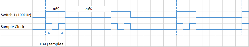
How to generate two pulses per cycle? PCI-6251/6255
Hello. I want to generate two or more pulses per cycle like the timming diagram. This pulse will be used to trigger the sampling data.
I am ussing the PCI-6251. The VI examples to counter outputs can easily generate the first line, but the second I have no idea. All information can help.
Another problem could be the synchronization of this lines and data acquisition.
Concerning
Ivan C.
I would like to use the digital outputs for this - just generate a continuous at 1 MHz clock using one of the counters and write the following in your digital output lines:
H H H L L L L L L L
H L H L L L L L L L
If you want to use these signals to pick a different spot on the 625 x, you the output of wire in a PFI lines.
Best regards
-
The self-calibration for VST (niVST self Calibrate.exe) utility has a button "Cancel". Is it possible to interrupt a self-cal, that was started by calling the niVSTCal_SelfCalibrate function in niVSTSelfCal.h?
Hello, where do you find the niVST self Calibrate.exe?
I notice that the function VSTSelfCalibrate in LabVIEW (Instrument i/o"instrument Drivers' NOR calibration VST' Self - Calibrate.vi is not an abandonment of entry, so I think that the text equivalent does not have this option.)
-
connect labveiw 8.2 with nor pci-6251
I have no pci-6251 and its cd driver with labview 8. How can I connect the daq with labview 8.2 and run programs
Hello
I can't download the driver of NOR-DAQmx 8.7.1, connect labview 8.2 with NOR-DAQmx PCI-6251...
Why?
Please answer...
-
Determination of 4070 self-calibration P/F
I calibrate by automatic programming 13 PXI-4070 DMM-based daily and must determine whether or not the auto-cal spent on each. I never had a self-cal failure so I don't know really what to expect. An error or a warning will occur? If Yes, what are the possible error/warning codes I need to check? Currently I compares the date of the auto-cal obtained from the DMM before you run the auto-cal with the date of obtaining self-cal post. I guess that the date does not change if the auto-cal fails. What is a good hypothesis?
Thank you.
S-T-G,
Depending on what environment you are programming in (b, LabVIEW, CVI, etc.) it will vary slightly know more precisely how you can determine whether or not any function going. A successful return of a function returns 0, so you can check for this. If you receive a nonzero number (you should if the call to auto-cal fails for some reason any), you can determine what means this error code. In LabVIEW, for DMM, you can use the IVI Error Converter VI niDMM to interpret the error. If you are using CVI, C, or another text-based programming language, you can pass a value of nonzero return to the niDMM_GetError() function.
Regarding the specific error codes that can be returned a failure of automatic calibration, there is a little, it is difficult to give you an exhaustive list but it can fail for various reasons (excess of scale, driver not installed correctly, etc.). The proper way to check for failure is to check against IVI_SUCCESS or equal to zero, then if she is unable to call the function appropriate to obtain descriptive error string. If you're curious, nidmm.h comes with the driver contains a list of the NOR-DMM more specific error codes.
For a better idea on how to do it, I suggest to take a look at examples of automatic Calibration that are provided with the driver.
I hope this helps. Let us know if you have any other questions.
Thank you
Tobias Gordon
Software engineer
Digital Multimeters
National Instruments -
Calibration and Simulation PCI-5112
Hello
I work in a lab where they use the PCI-5112:
http://www.NI.com/PDF/manuals/373495b.PDF
I had a few questions.
First of all, I would like to simulate this device on my computer using NOR-DAQmx, so I can play with a program we have on another computer with the actual hardware. However, it is not in the list when I try! Is it possible to "import" the PCI-5112 so that I can simulate it? If not, is there a similar device which recommends to someone?
Also by reading the specifications for PCI-5112, I saw this:
Ranges of vertical calibrated; ± 25 mV to ± 25 V in steps of 10%
Just to be sure, this means:
±25mV, 27.5mV, 30.25mV, 33.275mV, etc...
Or does this mean:
±25mV, 27.5mV, 30mV, 32.5mV... etc...
Therefore, if I select a voltage outside these values range, he finished not calibrated? Or he rounds up my entry to the beach close to calibrated?
I guess that the same answers to the question above also apply to the range of calibrated offset?
Finally, I have seen that the source internal must be calibrated to an external source, every year and the auto-calibration every 24 hours. I know that for some my lab is not the automatic calibration every 24 hours, and I guess that they never made it to an external source. With our experiences, however we are only concerned with the decay of an exponential signal measurement. Therefore, calibration would be a moot point?
Thanks in advance for your help and sorry for the multitude of questions!
See you soon
If you do not have external calibration, the values that you get from the card will be not as accurate as the data sheet says they are. This may affect the time and voltage values and time values will be less made, since the clock uses a quartz oscillator, which is very stable. Since you are using to measure the speed of decomposition, you should probably be OK. If you need really accurate timing, you can drive the 5112 from an external clock source that has been calibrated recently.
Maybe you are looking for
-
I want to change a DNS setting. How can I do?
-
How to reorganize the vertical tabs
I have the Vertical of the add-on tabs. Several versions of Firefox back, I could reorder the tabs by grabbing and by simply moving. Now it will not work. Is there a way to move tabs now. I have a tab I use a lot at or near the top and I added severa
-
Unable to connect to the Internet error "Windows does not detect a network card installed properly"
Internet does not connect and connection was well 5 hours ago. Message states: "Windows did not detect a network card installed properly" How should I proceed? Connection is on the laptop, but also other devices. Problem is only with the office. Any
-
I have smart touch Envy23 I had to refresh using windows 8 and now every few strokes the keyboard stop & I have to click with the mouse to restart.
-
My printer CM1312nfi has developed a problem by which it prints red streaks on the left side of the document. The four toner cartridges all indicate they are (relatively) complete, but when I take off and look at them closely, magenta streaks on the