Self-calibration OR VST
The self-calibration for VST (niVST self Calibrate.exe) utility has a button "Cancel". Is it possible to interrupt a self-cal, that was started by calling the niVSTCal_SelfCalibrate function in niVSTSelfCal.h?
Hello, where do you find the niVST self Calibrate.exe?
I notice that the function VSTSelfCalibrate in LabVIEW (Instrument i/o"instrument Drivers' NOR calibration VST' Self - Calibrate.vi is not an abandonment of entry, so I think that the text equivalent does not have this option.)
Tags: NI Hardware
Similar Questions
-
Determination of 4070 self-calibration P/F
I calibrate by automatic programming 13 PXI-4070 DMM-based daily and must determine whether or not the auto-cal spent on each. I never had a self-cal failure so I don't know really what to expect. An error or a warning will occur? If Yes, what are the possible error/warning codes I need to check? Currently I compares the date of the auto-cal obtained from the DMM before you run the auto-cal with the date of obtaining self-cal post. I guess that the date does not change if the auto-cal fails. What is a good hypothesis?
Thank you.
S-T-G,
Depending on what environment you are programming in (b, LabVIEW, CVI, etc.) it will vary slightly know more precisely how you can determine whether or not any function going. A successful return of a function returns 0, so you can check for this. If you receive a nonzero number (you should if the call to auto-cal fails for some reason any), you can determine what means this error code. In LabVIEW, for DMM, you can use the IVI Error Converter VI niDMM to interpret the error. If you are using CVI, C, or another text-based programming language, you can pass a value of nonzero return to the niDMM_GetError() function.
Regarding the specific error codes that can be returned a failure of automatic calibration, there is a little, it is difficult to give you an exhaustive list but it can fail for various reasons (excess of scale, driver not installed correctly, etc.). The proper way to check for failure is to check against IVI_SUCCESS or equal to zero, then if she is unable to call the function appropriate to obtain descriptive error string. If you're curious, nidmm.h comes with the driver contains a list of the NOR-DMM more specific error codes.
For a better idea on how to do it, I suggest to take a look at examples of automatic Calibration that are provided with the driver.
I hope this helps. Let us know if you have any other questions.
Thank you
Tobias Gordon
Software engineer
Digital Multimeters
National Instruments -
self-calibration of NI PCI-6251 (series M) using the kit DDK
-
Weird waveform using the PCI-5922
Hello
I'm having some difficulty with PCI-5922.
Rather than see a sinusoidal signal (generated by the PCI-5421), I see the forms attached wave, MAX and configured niScope EX Acquisition.vi
Sometimes he would turn to show a normal sine wave, often times it expires.
What could be a problem?
Thank you
Fomin
It's weird.
Could you give more details about your Setup?
(1) what is your operating system?
(2) what are the versions of NOR-SCOPE and NOR-FGEN you?
(3) you have another source of signals to test so that you can narrow down the problem to the digitizer or the generator?
(4) can we measure the same thing on the channel 0 and channel 1?
(5) what is expected of your sinusoidal signal amplitude?
(6) what is the result of executing a self-calibration on two of these cards?
-Jennifer O.
-
implementation of a push button
Hey I just started using Labview and I need for a project on the recording of the results of strain gauge. I wrote a code for data recording, but I don't know if he needs calibration I use the NI 9237 strain gauge module and how to proceed to make the calibration? I tried the example find in Labview but its me gives an error and I do not understand FPGA. My second question is I want to use a digital input module to implement a push button so that the code turns on when its market and it stops logging when you press OFF. I do not know how that proceed and what is needed in the code to do this. I posted what I have so far and any help will be appreciated. Thank you
"I don't actually like using the term 'guru', I actually perfer LabVIEW Overlord." It really scared in the peasants of LabVIEW. »
But seriously do anything is going to take a long time, is there no reason not to learn something. Heck that's why universities, people are going to lose time to learn.
Back to the original question a bit. NEITHER offers calibration options
http://sine.NI.com/NIPs/CDs/view/p/lang/en/NID/207895
https://www.NI.com/services/calibration.htm
http://sine.NI.com/NIPs/CDs/view/p/lang/en/NID/207957
http://www.NI.com/white-paper/12788/en/
Some hardware supports self-calibration but most don't. You can also perform the calibration of your car, but I can't find the documents for this right now. I think there is an example in the Finder of the example on calls to set the calibration offsets in the material.
-
6036E DAQ works do not at the same time - OR-MAX-Bug?
Hi all
I'm stuck with a strange question with two cards PCMCIA-6036E running on the adapters on a W7 32-bit desktop machine.
The adapters are two Texas Instruments PCMCIA adapters PCI-slots (show different IRQ in windows device manager).
But NEITHER MAX (5.6.0f0) doesn't recognize only one card, no matter what I do.
Only 1 card works in both slots adapter
Card 2 working alone in both slots adapter
But as soon as I place the second card in the other slot (any combo of it), it does not appear in the NOT-MAX Device Manager (itshows upward in the windows Device Manager, however).
I noticed that the serial number of the map displayed on the NOT-MAX preview is not updated tab if I switch cards - although I can see the serial number valid in the tab 'attributes', respectively.
Name change (Dev1--> Dev2) is not the case.
I suspect some sort of software problem; may be connected with the same serial number. It seems as if NEITHER-MAX is unaware of the second card, although they (or adaptors) seem to be clearly distinguished by windows. Maybe a problem of updating internal?
Another symptom: I plug in map 1 and test (work), I also connect card 2 (not recognized) then I remove the card 1 and NOR-MAX always tells me that a card is installed. But the serial number is not updated and tests/self-calibration fails.
I have not found any mention of such behavior. I now have to work with two separate computers that is terribly boring.
Any suggestions? This has been filed as a bug, or is there compatibility problems with PCMCIA adapters?
Thanks for reading!
Okay, so I got an adapter PCMCIA alternative (different chipset), until the last DAQMX-improved version but no change - it is one or none.
According to me, it's rather a problem in NI MAX Panel and not driver related - but since there is no real prospect of a solution, I give up.
I'll mark this issue "resolved", even if it is not in a technical sense. It does not work as I want.
Thanks for your suggestions!
-
PCI-6111 is recognized as PCI-6110
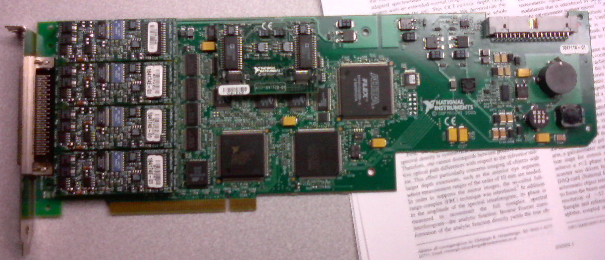
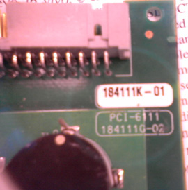
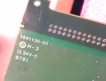
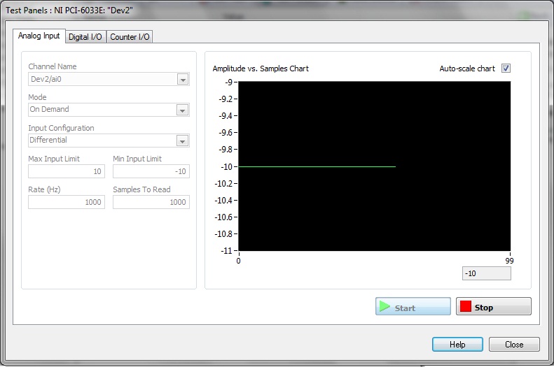
I have a Board OR marked as PCI-6111, but when I inserted in a PC, it has been recognized as PCI-6110. Subsequently, none of the inputs or outputs work. The analog inputs still show a flat 10V line, while the exit is blocked to 500 mV. The card go through self-control, however fails self-calibration. Reset of the card does not resolve the problem.
Based on the images below, what a card 6110 6111? Could he just scored, in which case the card is probably damaged?
It looks a little dfferent PCI-6111 cards available to us, but perhaps that is a previous model (it had been built, it seems, in 2000).
Or might pose the problem with inputs and outputs that the PC does not correctly recognize it? If this is the case, is there an easy solution (in relative terms) of the problem, sending to OR for repairs?
Thank you for reading.
Filipp,
Where did you got this card? It is a very strange problem. 184111 K-01 part number is for a 6110. The part number 184111 G-02 is for a 6111. The jury is without a doubt a 6110 as you can see the 2 of the 6111 4 chips on the left hand side related to the 4 channels of the 6110 vs. So I recommend you all what's wrong with that you send it back in OR for repair. You can give me a call at 1-866-275-6964 SEO SR #: 1436085 and I can help you through the process of RMA from here.
-
Strange analog output of USB-6211
I just got USB-6211 to replace USB-6001 to set the clock to external sampling on analog output for LED lighting control. The part of external clock example works fine, but the analog output voltage is strange. To do self-monitoring, I connected control pin LED to AO0 & AI0 of surveillance in the NI MAX test panel and LED control on the ground at AO - GND & GND HAVE since I have both USB-6001 and USB-6211, I conducted tests on two of them with the same setting of wire. When I generate sine wave - 5V to 5V to AO0 (from NI MAX test panel), USB-6001 can monitor the same signal AI0, but watch USB-6211 - 3, 4V to 3.4V voltage truncated. I did the test separately (wiring one device at a time), so there is no interference between the two devices. USB-6211 past self-calibration and self-monitoring. Also, I did reset devices. I don't know why they would behave differently with the same configuration, and I hope that someone could help with this question. Thank you.
Hi skuo1008,
The USB-6001 can support + / 5 output current my from terminals to analog output, while the USB-6211 box can provide only +/-2 my current output. It is likely that the load impedance is too low, causing the 6211 to hit its current compliance and thus cut the tension. If you try to exchange your load with a resistance of at least 5 v/.002A = 2500 Ohms, you should be able to see the full +/-5V sine wave. I suspect that your DUT has a words 3.4V/.002A = 1700 Ohms impedance. You could use a device with higher output current or use a more current source buffer circuit. If you do not need a bipolar output, you might also consider using digital lines to control the LEDs.
Kind regards
-
Incorrect, test the results of the e/s digital PCI-6024E in MAX
Hi all
I have a problem with PCI-6024E. It is for the Commission alone OR installed on a target computer. First he just used OR-traditional DAQ (7.1, if I'm not mistaken) and it worked fine. Some time ago I installed NOR-DAQmx 8.7.1 on the same computer because it is necessary to run both programs written with NOR-DAQmx and NOR-traditional DAQ. As I know there is no harm to do both OR-DAQ and NOR-DAQmx on the same computer if they are not used at the same time. You can see the traditional under NOR-DAQmx devices and peripheral branches DAQ PCI-6024E jury in MAX. When I run the self-test, self-calibration or Reset Device, Max there is no problem. But Test panels (under the direction of NOR-DAQmx) has a rather strange behavior. When I press the "Start" button in tab e/s digital Test panels window with all the digital lines in input, the 4 first green indicators are on and the other 4 are not. And then nothing happens or I press the 'Stop' button or not. I have the same card as a virtual in my MAX on a development computer, and there is a different behavior of it (I don't have traditional DAQ here, just the same version DAQmx). During the entire procedure of test until I press the button 'Stop', the port State 8 lines constantly evolves so the Green indicators are switched on and off with different ways through all possible combinations of logic '1' and '0' in each line of the port.
The problem is really obvious when trying to control the statements of some laboratory equipment using their passage through PCI-6024E. digital controls. In this case I get auto turn on/off devices connected to the first 4 lines (which are always lit for some reason any as stated that the Green indicators).
What should I do? This means the Agency is malfunctioning or there is some conflict of data acquisition and acquisition of data-mx? I would try reinstalling DAQ - mx, but I don't think it's a way out of the situation. I work under Windows XP SP2.
I appreciate all help.
Igor-
Your digital outputs will remain in their last State configured unless the device is reset, in which case they will go to the default value (high, in this case). So if the last State of the low output of your digital program, as long as you do not call the Device.vi DAQmx reset or shut down the computer, they will remain weak.
If you have other questions about this application in LabVIEW, it would be better to create a new post on the forum so that we can keep these two separate issues (States of I/O digital by default against digital programming in LabVIEW). If you are looking for a starting point, you can open the Finder example in LabVIEW ('Help' to find examples). "" Once the example Finder opens, click on input and output material"DAQmx ' digital generation ' write Dig Chan.vi. This will help you start.
Better luck with your request and have a great day!
-
PXI-6120 HAVE values only show the low limit values
Hello, I use a PXI-6120 with traditional DAQ driver module screws switch a signal of AI to a PFI channel that allows synchronization of area of OCCUPANCY the AI. In order to measure a single channel of AI with the same set-up, I stopped the criterion VI and tried to see the only measure max. Unfortunately, I opened a task DAQmx, I created for another application, which does not work probably because I have not reset the card after the stop of the VI. Since then, readings of IT are all flat on the lower limit values and the OD has remained at about 0.2 volts any value I write for her. In the meantime, I tried to reset and to recalibrate the device, which worked in DAQ and DAQmx (not the self-calibration in mx). But I have the impression, that the Council has kind of stuck in a State that I can't easily find and/or access. Does anyone have an idea, how can I do a factory reset, or what could be the problem? Greetings! Olli
-
(Mic) audio system automatically set too low - Captivate Win 9/10
Well, I'm trying to record video demos with Captivate 9 (9.0.1.320) and for some reason any, it puts my audio system (record; microphone input) at age 13, although I always set it to 100. Very annoying, because sound levels are so quiet during playback I can't even hear with my headphones turned up 100. I'm not using the auto calibrate.
What I'm missing here?
Thank you
Edit: I should also add that I tried self-calibration, but audio is still set to 13. I even turned off the 'exclusive' modes in the system microphone settings.
Figured it out. The preamp volume is a.125 (~ 13%) by default. Changed to 1.0 and all is good.
Don't know why self-calibration did not work well.
-
VST: entered password for calibration of VI
Where do we get the password, which is a string input required for the screw for the VST calbration?
The default password of calibration is 'NOR '.
-
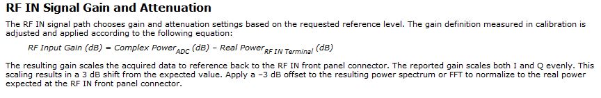
Vst 5645r PXI gain / attenuation calibration chain RX TX
Hello
I work with PXI vst 5645r. I did some research using the RF output of the transmitter connected with the receiver RF input.
In my application, it is important to know the equivalent mitigation and win I get (output of the DAC) generation up to the acquisition (input of the ADC) (loop gain).
I looked at http://zone.ni.com/reference/en-XX/help/373680C-01/vstdevices/5645_analog_input/ and http://zone.ni.com/reference/en-XX/help/373680C-01/vstdevices/5645_analog_output/ in order to better understand how to build the structure of my channels.
Whole, I looked in the drawing in labview how these parameters are controlled and value (example VST streaming (host)). I found only the configuration of gain for the transmitter in the 'LO_cal' block but I don't see no calculations for the various mitigations of transmitter. I have to check these datas for the transmitter.
How are managed and put all these settings in the transmitter and the receiver normally?
I guess that the receiver channel attenuates the signal in order to use the dynamic maximum range od a/d converters and use good power from receiver... calibration changes the values of gain/attenuation in the receiver string whenever I use a different gain (peak power dbm) of the issuer?
Thanks in advance
Best regards
Giuseppe
The reference level is a 'guide' for the driver VST set the attenuators and win as well as the range of the ADC/DAC are used at best.
Depending on the frequency that you and the chosen reference level, the VST pilot will focus on the best combination of the mitigationsand win to get the Signal arriving at the ADC to use his full range:
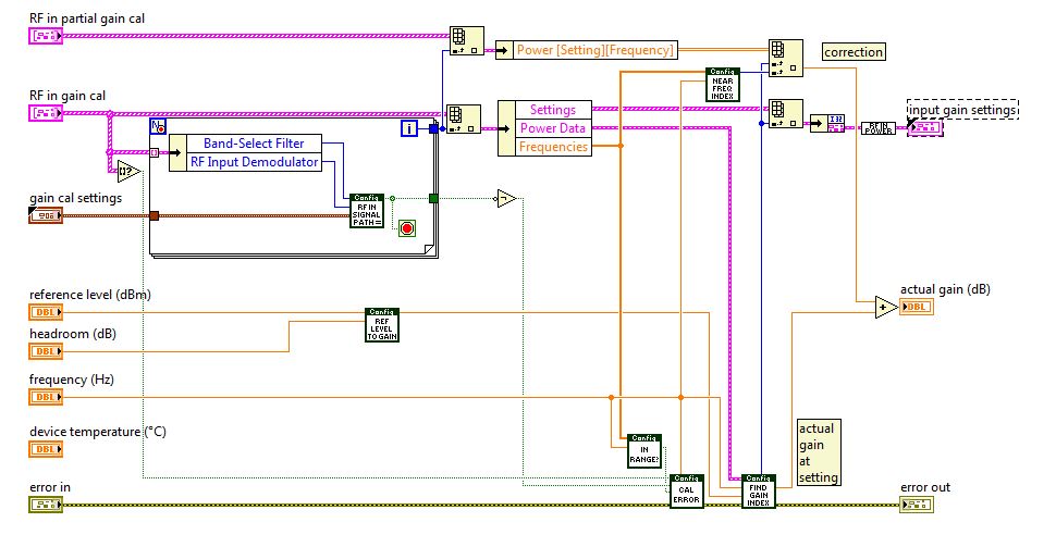
You can see the calculations in this niRFRIO Group A Config 1.0.0 Shared Private.lvlib elect RF calibrated Gain.vi
This Gain is 'Gain of frequency step-down converter' that summarize the entire path of Rf In.
So practicall frequencies/Upconverter Gain step-down converter is the total analog gain that is put on the signal just before and after the ADC/DAC.
This is done in the niRFRIO Group A Config 1.0.0 Shared Private.lvlibelect RF calibrated in Gain.vi.The discovery to Gain Index scan all possible power levels for this frequency and get the level closest to the chosen reference level.
Whith this information, he knows what attenuators and win it must reach the power to get at its best at the ADC (input gain settings)
So to calculate the loop gain, you must define a level of refeerence fix so that all mitigations and gain in the two paths of remain fixed, test it with a calibrated CW and then use this configuration for your DUT.
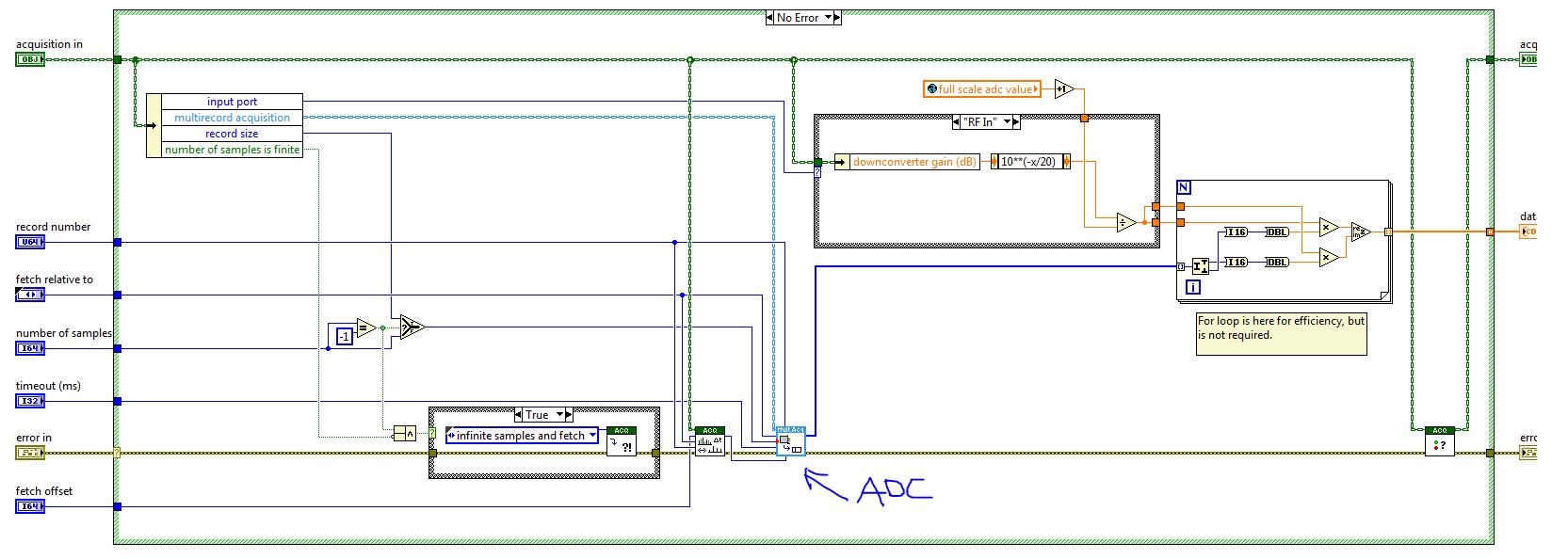
When you read the QI of the VST (retrieve a single record) this information is passed to the function, so it can calculate the values of CDA and calibrated to their actual value on the RF In:
If you calculate the gain of loop inside the FPGA, then he must send the information of step-down converter frequency/upconverter gain between the host and the FPGA. You can then use this information to calculate the loop gain.
Best wishes
-
200545 PCI-6033e auto calibration error
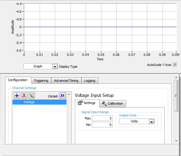
I have a PCI-6033e card that worked for a long time on an old computer (Windows 2000) who recently has the same problem, as described in THIS post. The measured voltage in all NOR-DAQmx tasks, or any VI run by BT is always the minimum voltage value in the negative area, without noise (that is, - 5V, - 10V etc.). When the voltage range is set to 0V more (i.e. 1V - 5V) the voltage is constant 0V.
I don't think I have the same problem as in the post I linked above because my card does not work on two separate computers. While the post above, the map worked in a computer and not the other.
I am trying hard to draw the card on a "new" computer (Windows 7) and have the following questions.
On both computers, old & new:
-New versions of the drivers have been downloaded and updated.
-Card past self-test-Card can be reset.
-Card fails Auto Calibration (200545 error)
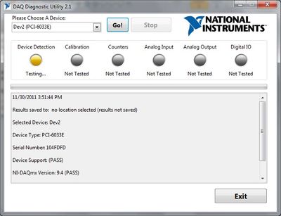
When I run the utility DAQ Diagnotistic 2.1, it get hung up after the next step:
30/11/2011 15:46:58
Results saved in: C:\Users\UWABL\Documents\Diagnostic results.txt
Select device: Dev2
Type of device: PCI-6033E
Serial number: 104FDFD
Support: (PASS)
NOR-DAQmx version: 9.4 (PASS)
Resetting the device: (PASS)
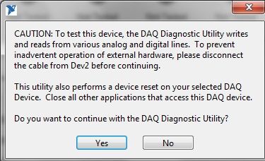
At this point, the utility Diagnotistic DAQ 2.1 has a warning to disconnect the cable to the DAQ hardware to prevent involuntary actiavation of instrumentation. However, there is nothing connected to the acquisition of data. When asked if I want to continue, the utility DAQ Diagnotistic says 'stable' but do not process with the Diagnotistic test.
Warning
Declare that the DAQ Diagnostic Utility is stuck in after I told him to continue.
Any ideas when it comes to a bad card, or it must be sent for calibration would be appreciated!
Thank you
Jeff Campbell
Hi Jeff,
Thank you for taking to the extent additional and based on the results, it seems that the map is carried out. I don't think that it is a calibration problem either since there is absolutely no response to the signal on the oscilloscope. It is clear, since you've tried the same signal on another card and it worked. If you are looking to replace the card, 6033e PPI is no longer available, but you can visit our page http://www.ni.com/daq/multifunction to see the new M series and the maps in the series X. Let me know if you have any questions, please!
-
W510 - error HARD drive, gambling problems, calibration of the questions
Hi all users of Thinkpad and Lenovo. I'm new here and to the community of Lenovo.
I just renovated W510 a few weeks and love it. Laptop necessary for photography.
Type series R96RGY4 43195RU
i5 520 M
6 GB of RAM [Update 2GB]
Quadro FX 880M 1 GB
HD + screen 15'6
Seagate 320 GB SATA 7200 RPM
Windows 7 32 bit
Update Bios to 1.38
But having some issues, could not find an answer:
1. as a hobby photographer trying to calibrate using Huey PRO Lenovo recommended tool. Problem is that when I run the software says "could not find the color sensor" and I don't know if I have it. I know, it should be between the fingerprint and keyboard player. What it looks like? How will I know that I have?
If I don't have it, what is the best [possibly budget] way to go on the calibration it?
2. question - half-life 2 game. Downoladed by Valve. Played very well from the beginning with the "recommended" video settings But lately the game FREEZE a lot, it's unplayable!
I installed the latest driver from nVidia 6824, always point of FREEZING. I did back driver, still hurt. [if I remember well, it was well before I did of the nvidia drivers] I lowered same resolution details changed from the top in the middle. None works.
I use GPU counter acquired with Win 7 and it will never more of 130 f. I even had laptop cooler with 2 adjustable fans, adjusted on the GPU area. If the heat is not the issue.
3 HDD issue.
Due to the game that I have run Thinkvantage material test and found 2 ERRORS [could there be FREEZE game question?]
FAILURE - ERROR WHD20-SR7 targeted reading test
FAILURE - SMART self-test short ERROR WHD16-59Y
Here found navigation I use Lenovo Diagnostics bootable CD. I did and got:
Repair of sector test ATA failed - ERROR ID09H-0 CT code "your drive could not be repaired and must be replaced" [nice]
I want to emphasize that I installed Xubuntu Linux as a 2nd distribution. HDD shrunk using the Windows utility, install Grub in the MBR.
All workes very well, except the game.
Can I communicate with Lenovo and replace the HARD drive? About 198 days warranty.
Sorry for the long post, did not make too many messages :-)
Thank you for reading and I would appreciate any help. This day happy user of Lenovo.
The W510 series is known for having badly mounted coolers, I'm not sure if this applies to Dual Core versions however.
Even if your time is low, the video memory could be overheating because the cooler has bad contact with them.
Have you checked the time CPU? What heppens if you run FurMark at extreme burning mode?
Temp monitor:
http://www.CPUID.com/softwares/HWMonitor.html
FurMark:
http://www.oZone3D.NET/benchmarks/fur/
You should have this replaced hard drive that's for sure.
Maybe you are looking for
-
How can I get assistance with my Apple Care Protection Plan when I am abroad
How can I get assistance with my Apple Care Protection Plan when im abroad? I brought an iPhone 6Plus in Europe and now I am traveling I would like to know if Apple Care Protection Plan cover me in the United States and what I can do
-
Recently joined motorola, how to become part of a penetration test?
I just recently signed to motorola and the feedback network. How do I volunteer for soak tests for the droid 3 or become a beta tester of the firmware/updates? I hope that a new update is right around the corner for the droid 3 which solves the probl
-
Why can't I synchronize all the new music I bought on my ipod?
I bought a new computer. I don't see all the music that I bought this computer on my ipod. Please help me understand how to get my music purchased from the computer.
-
Concatenation of Hex and bites of ASCII to get a HEX string
Hello I'm trying to concatenate a MODBUS Application Protocol header with a function code and data that I send over TCP/IP to a motor controller. I am running problems when I try to read my code function and data length. I use "string length" to re
-
HP Officejet 7310 transport Jam
I tried all the recommended solutions and still cannot get it printed, he tries, but then I get the error message Jam of transport Door open, clear transport jame and then press OK to continue.